293
Diesel injector dynamic modelling and estimation of
injection-parameters from impact response
Part 1
:
modelling and analysis of injector impacts
F Gu, MSc and A D Ball, BEng, PhD
School of Engineering, University of Manchester
Part 1 of this paper presents the development and validation of a detailed dynamic model for the needle motion of a common hole-type diesel fuel injector as used in a direct injection diesel engine. The injector needle motion is described as a two-mass piece-wise linear vibro-impact system, unlike the conventional modelling techniques which use a single-mass approach. The use of two masses permits analysis of both the needle impact behaviour and of the more general dynamics of the fuel injection process.
Model parameters are derived from a combination of measurement and estimation, and the subsequent model is evaluated via direct measurement of the spring seat displacement. The opening and closing needle impact behaviour is shown to exhibit close correlation with key injection parameters, including fuel injection pressure, fuelling rate and timing.
The model revealed that the impact of the needle when opening is found to exhibit lower amplitude but more high-frequency components than the impact associated with the closing. The measurement of the injector body vibration response to these impacts is shown to enable non-intrusive estimation of injection parameters, alleviating the problems associated with conventional intrusive needle-lift mea- surement.
Key words: fuel injector, condition monitoring, injector vibration, impact vibration, time-frequency analysis, injection pressure, injection timing
NOTATION
speed of sound
cross-sectional area of nozzle chamber flow coefficient of nozzle holes
in-flow coefficient
damping ratio of elastic contact damping ratio of needle motion force due to injection pressure acceleration due to gravity stiffness of injector return spring
Stiffness between needle tip and needle seat stiffness between rear of needle and spring seat
stiffness between needle collar and back stop mass of needle
mass of spring seat plus effective mass of spring
injection pressure cylinder pressure rate of fuel in-flow rate of fuel injection
forced due to pre-load spring maximum needle lift
time
half period of in-flow rate
displacement, velocity and acceleration of needle
displacement, velocity and acceleration of
needle seat and spring mass
static deformation of needle seat contact zone
static deformation of needle rear contact zone
fuel bulk modulus
The MS was received on 4 April 1995 and was accepted for publication on 28 October 1995.
W1795/1 0 IMechE 1996
P fuel density
1 INTRODUCTION
1.1 Injector operation
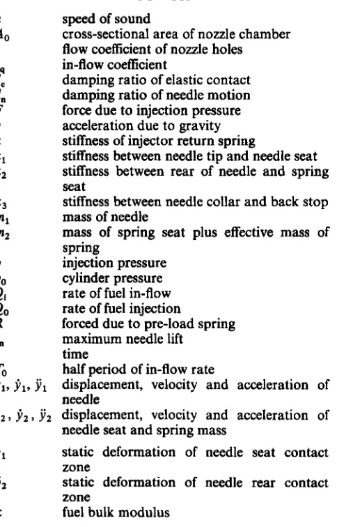
Figure 1 details the construction of a typical hole-type direct injection diesel fuel injector. The injector acts as a diesel fuel valve, allowing the controlled introduction of fuel into the cylinder. Prior to injection the needle is held in contact with its seat, and covering the fuel outlet holes, by a pre-loaded spring.
At the time of injection, fuel supplied by the high- pressure injection pump flows first into the upper injec- tor chamber and from there into the lower chamber (or
tip sac). The fuel in the upper chamber exerts a lifting force on the needle collar and when the fuel pressure exceeds the pre-set opening (that is breaking) pressure, the needle lifts off its seat, uncovering the outlet holes, and injection commences. Depending upon engine load and speed, the needle may retract sufficiently to hit its backstop, resulting in a needle opening impact.
At the end of the injection period, a spill port opens in the fuel pump, the fuel line pressure falls (accompanied by a back-flow of fuel) and the upper chamber pressure drops below that value required to keep the needle retracted and the valve open. The needle advances back to its seat, terminating the injec- tion process and generating a closing impact.
There are thus two mechanical impacts associated with the injection process. Each of these impacts is likely to consist of a brief series of collisions or bounces between the needle and a part of the injector body.
1.2 Measurement of fuel injection parameters
The ability to quantify the key fuel injection parameters of injection pressure, injection rate and injection timing is important because they are fundamental to engine
[image:1.594.49.291.362.740.2]294 F GU AND A D BALL
n
Preload spring
Spring seat
Back stop
Needle
/ Upper fuel chamber
11
IN
,Nozzle charnber(1ip sac)(a) Construction (b) Model
Fig. 1 Schematic and dynamic model of an injector valve
performance and emission control. It is common to perform experimental studies to obtain values for the injection parameters, using direct and intrusive mea- surement (1-3). The intrusive nature of such experimen- tal investigation influences the injector dynamics and detriments injector performance, meaning that the mea- sured characteristics are not representative of the injec- tor in its original state. In addition, intrusive measurements cannot be made without permanent, costly and damaging modifications to an injector.
Clearly, a non-intrusive experimental (and preferably on-site) approach, capable of providing accurate esti- mates of the injection parameters would be a consider- able improvement to the characterization, set-up and fault diagnosis of injection systems. To develop such a method, based upon monitored vibrations, it is neces- sary to model the dynamic behaviour of a fuel injector.
1.3 Modelling of injector dynamics
Mathematical modelling procedures have long been used in attempts to predict injection parameters, with needle motion models being developed as sub-sets of models of the complete injection system. These pro- cedures are often applied in the investigation of overall injection system behaviour, such as the influence of physical design changes upon injection performance.
It is conventional to model the needle motion as a single degree-of-freedom mass-spring system (4-6), with the needle and spring seat as a single entity. These models are based upon the equilibrium conditions of the fuel pressure, spring and inertia forces acting on the needle. In reference (7) a model is presented in which the damping force due to needle motion is taken into account. Possibly the most detailed model is reported in reference (8), which in addition to damping, incorpor-
Part D: Journal of Automobile Engineering
ates needle seat stiffness. Using this model, good corre- lation has been demonstrated between calculated and measured rates of needle lift.
Clearly, non-intrusive estimation techniques utilizing monitored vibration must be based upon the vibration which is transmitted to the injector body; such vibra- tion is the response to the impacting of the needle. The form of the injection impacts is a consequence of the needle motion and is hence influenced by the param- eters of the injection process. To be able to predict the form of the body response to impact excitation, a more accurate needle model than the traditional one must be developed, and in this study a two-mass vibro-impact model has been employed.
The layout of the paper is as follows: Section 2
describes the development of a needle motion model ;
Section 3 discusses the selection of model parameters, the validation of the model and its numerical implemen- tation; Section 4 investigates the needle impacts and their correlation with injection pressure and fuel injec- tion rate; Section 5 discusses the influence of intrusive needle lift measurement upon fuel injection parameters; and the final section draws conclusions from the study.
2 THE NEEDLE MOTION MODEL
2.1 Model terms
In the development of a mathematical model, it is necessary to consider the effects of each of the injector components in turn. A factor of considerable influence to the needle dynamics is the stiffness of the injector return spring k. In addition, there are three contact junctions within the injector: firstly, the junction between the tip of the needle and its seat, secondly the junction between the rear of the needle and the spring
DIESEL INJECTOR DYNAMIC MODELLING. PART 1 295
seat, and finally the junction between the needle collar and the needle backstop. The stiffnesses of each of these junctions are of the same order of magnitude, and hence a term representing each of these values must be incorp- orated in the model. These values are denoted
k,,
k,and k3 respectively.
The incorporation of a term describing the stiffness of the junction between the rear of the needle and the spring seat, dictates that the model involves two masses: a mass representing the needle m,, and a mass rep- resenting the effective mass of the spring and its seat
rn,
.
This effective mass has been taken to be the mass of the spring seat plus one-third of the spring mass. Them, mass component can be adjusted to take into account the mass of a sensor assembly when consider- ing the influence upon injector dynamics of convention- al direct needle lift measurement. The displacements, velocities and accelerations of the needle mass m, and of the effective sprindseat mass rn, are denoted by y,, jl, y, and y2
,
j ,,
y, respectively.The final dynamic consideration is that of damping. In addition to the structural damping properties of the injector body, the fluid damping effects of the high- pressure diesel fuel surrounding the needle must be con- sidered. In the model, these parameters are represented as damping ratios dcand dn respectively.
The two key forces involved in the dynamic operation of a fuel injector are the dynamic force F(t) exerted upon the needle by the high-pressure diesel fuel which attempts to lift the needle, and the static reaction force
R of the pre-loaded needle closing spring, which attempts to keep the needle in contact with its seat. Only when F > R does the needle lift from its seat.
2.2 Needle motion
Figure l b in Section 1 depicts a lumped parameter equivalent of a fuel injector. From this figure it can be seen that the motion of the injector needle can be broken down into a combination of four effects, of which three and sometimes all four will occur during an injection cycle.
2.2.1 Effect I-cornpression or relaxation of the needle
As the fuel pressure rises from its residual value towards the opening pressure of the needle valve, the contact force between the needle and its seat relaxes, and the needle retracts a very small distance. Similarly, at the end of the injection cycle, when the fuel pressure drops and the needle returns to its seat, the needle will be compressed into the seat due to the action of the pre- loaded injector spring, and it will also be compressed into the spring seat. Under each of these conditions, the motion of the needle is within the range of static defor- mation 6, of the needle seat contact zone 6, and of the spring seat contact zone. In these phases of needle motion, the needle and spring seat contact stiffnesses and mechanical damping govern the motion. The describing equations for this motion (with boundary conditions applied) can be written
seat
M I + 2Cd:d,J(hJ
+
dcJ(klml)j,+
( k ,+
k2)Yl-
b y , = F(t) Q IMechE 1996with y,
<
6, and y2,-yy,<
6,2.2.2 Eflect 2- the retraction and advance of the needle When the fuel pressure becomes sufficiently high to lift the needle from its seat, the needle retracts against the pre-loaded injector spring up to a maximum needle lift of s,. In this phase, the motion of the needle is influ- enced by the stiffness of the injector spring, and also by the contact stiffness between the needle and the spring seat. When the fuel pressure falls below the opening pressure of the valve, the needle will advance under the action of the injector spring, back to the needle seat. As
such, the motion can be expressed as follows:
m l J 1 +
2 d n J ( h l ) j ,+
k 2 Y ,-
k , Y Z = F(t)m2 Y1
+
2dnJ(km2)j2+
(k,
+
~)YZ-
kz ~1 = --R (2)with d1
<
y,<
sn and y,-
y ,<
6,2.2.3 Effect 3-the impacting of the needle with its back
Under certain operating conditions, when large quan- tities of fuel are being injected, the fuel pressure in the injector may be sufficiently high to cause the needle to impact with its backstop. Upon first making contact with the backstop, the needle will continue to retract due to elastic deformation of the needle-backstop junc- tion (stiffness k3). The equations of this motion can be written as
stop
2.2.4 Efect 4-spring seat and needle separation
When the needle is brought to rest by its impact with the backstop, it is feasible that the injector spring may continue to retract due to the inertia it gained because of the imparted velocity. In this situation, the spring/ seat mass
m,
will become separated from the needle massrn,.
The motion of the system can thus be described by two independent single degree-of-freedom modelsm2 ji,
+
2d,J(km,)j,+
ky, = - R (4)with y, > 6 , +s, and y, - y l > 6 ,
In combination, these four cases describe the complete motion of the needle throughout the injection cycle. Of
particular interest are the vibrations resulting from the various impacts. The collisions associated with the needle opening impact are described by the equation sets (2), (3) and (4); and the collisions associated with the needle closing impact are described by equation sets (1) and (2). The regions of influence of each of the four equation sets are labelled upon the needle displacement trace shown in Fig. 2.
296
0.2-
2
E
Y
*
f 0.1-
U
-
2 .a
0 3 -
z
E .
I
E 0.1-
2 .
a
-
33
un--
F GU AND A D BALL
01-,
1 ' 1 I '
(cj Predicteh needle lift
I
(a) Directly measured needle lift(b) Predicted seat motion
I I I I I I I I I
0.0 0.2 0.4 0 1 0-8 1.0 1.2 1.4 1.6 1J 2.u Time (mi)
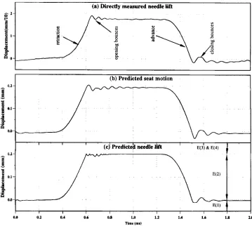
Fig. 2 Comparison between measured and predicted needle lift
Due to the difficulty in obtaining a closed solution to four sets of equations, a numerical simulation approach was adopted in the study of the needle motion and its subsequent impacts. The aim of the numerical approach was to solve the four sets of differential equations describing the needle motion, and the single differential equation describing the fuel flow. A fourth-order Runge-Kutta scheme was adopted, incorporating adaptive step size control and fixed time interval output. The adaptive step size control was based upon a maximum permissible error of O.OOOO1.
Together, the four sets of needle motion equations describe the complete motion of the injector needle throughout the injection cycle. The transition from one set of equations to the next in the sequence is controlled by the boundary conditions of these sets, with the solu- tion for a given set providing the initial conditions for the subsequent set. The computational procedure was written in Fortran and was performed on an HP-7000
computer.
3 PARAMETER ESTIMATION AND MODEL VALIDATION
The test engine in this study was a Ford FSD-425 2.5 1 direct injection diesel and the model was applied to the Lucas CAV hole-type injectors fitted to this engine. A schematic section of this type of injector is given in Fig. 1 (Section l), and its specifications are summarized in Table 1.
Before the model could be evaluated, values had to be obtained for the various model parameters. Obtaining
Part D: Journal of Automobile Engineering
some of these parameter values by direct measurement on the injector is difficult. For this reason, values for the contact stiffnesses and the damping ratios were initially estimated and then adjusted iteratively until a needle lift diagram close to that obtained by conventional induc- tive measurement (2) was achieved. In addition, the problem of estimating the pressure in the injector cham- bers (and consequently the lift force on the needle) is side-stepped by adopting a compressible flow relation- ship between the rate of fuel in-flow
Qi
and the chamber fuel pressure p.3.1 Fuel flow
The motion of the injector needle is controlled primarily by the flow of high-pressure fuel within the injector body. For this reason, the dynamic behaviour of the fuel flow must firstly be defined. Considering the basic fea- tures of the fuel flow in an injection system, and assuming for computational simplicity .that the fuel flowrate in the injector chambers varies sinusoidally, the
Table 1 Injector specifications
Injector type LRB6701601
Nozzle type CAV 6801024
Number of holes 4
Hole diameters 0.25 mm
Needle seat diameter 2.4 m m Needle guide diameter 4.5 nun
Maximum needle lift 0.2 mm
[image:4.594.114.473.59.381.2]DIESEL INJECTOR DYNAMIC MODELLING. PART 1 297
following expression for fuel flow arises:
Qi = Cq Qmax sin C(nt/cq
TO)]
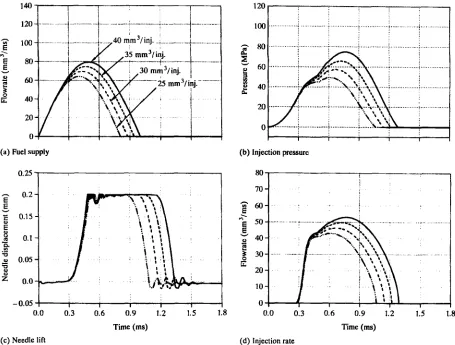
( 5 )There are several advantages associated with the use of a model of this type. Firstly, it is possible to assess injec- tor behaviour for a range of fuel supply quantities, and secondly, given a total volume of fuel delivery, the fuel supply and injection speed characteristics can be varied by adjusting the amplitude Qmax and duration To. For example, Fig. 3a shows a range of fuel supply profiles, each delivering the same total quantity of fuel. An in-flow coefficient cq is used to simulate the behaviour of various fuel supply settings by maintaining the same supply profile but varying the total amount of fuel delivered. The pressure in the nozzle chambers can be found from the following continuity equation :
Where Vo and A , are the chamber volume and cross- sectional area respectively. Using the steady-flow orifice equation, the injection rate Q, of fuel into the cylinder can be obtained from
QO = ~ A o / ( 29 P
p)
- Po(7)
Since cavitation effects have not been considered in this model, the fuel properties are those of a single phase fluid and as such they depend upon pressure and tem- perature alone. Assuming the temperature to remain
constant during the injection process, the fuel density p, the bulk modulus of elasticity icy and velocity of sound
in the fluid a are only dependent upon pressure. From the test data described in reference
(7),
it has been shown that the relationship between sound velocity and pressure is given bya = 4 . 6 9 ~
+
1330 (m/s) (8)K = paZ (9)
with the bulk modulus of elasticity K defined by
The flow coefficient c of the nozzle hole in equation (7)
is determined from the study reported in reference (5) to
be between 0.6 and 0.7. Because the effective area of the nozzle hole is influenced by the degree of needle lift, c is also exponentially weighted according to the needle lift characteristics, a procedure described in reference (7).
250
!
1
3.2 Needle motion
Values for the contact stiffnesses and material damping parameters could be obtained by theoretical analyses, but such calculations for a fuel injector are highly complex. Near-values are sufficient to enable the model to replicate quite accurate needle motion behaviour, and for this reason, the material spring constants and damping coefficients have been assumed linear and their values have been obtained empirically by correlating the model-predicted needle lift behaviour with a directly measured equivalent.
" ? I I I I 1
(a) Fuel supply
0.25
-
0 . 0 5 5 10.0 0.3 0.6 0.9 1.2 1.5 1.8
200 I I
(b) Injection pressure
100
I
h 0.2-
E
E
t 0.15-
v
E
P
0.1-B
s
u 0.05-
B
0.0-
-
Time (ms) (c) Needle lift
Q IMechE 1996
0.0 0.3 0.6 0:9 1.'2 1.5 1.'8 Time (ms)
(d) Injection rate
Fig. 3 Injection speed behaviours at a fuelling of 35 mm3/injection
[image:5.594.71.521.407.748.2]298 F GU AND A D BALL
(a) Fuel supply
0.25 3 I
- 0.05
0.0 0.3 0.6 0.9 1.2 1.5 1.8 Time (ms)
(c) Needle lift
I
I I I 1 I(b) Injection pressure
0.0 0.3 0.6 0.9 1.2 1.5 1.8 Time (ms)
[image:6.594.72.527.50.395.2](d) Injection rate
Fig. 4 Injection fuel behaviours at a speed of setting 1.0 m/s From the upper trace of Fig. 2, it can be seen that the
directly measured needle lift is divided into four phases: (a) the needle retracting;
(b) the backstop bounces; (c) the needle advancing; (d) the needle seat bounces.
The rates of needle movement in the retracting and advancing phases are dependent upon the fuel pressure force, the injector spring pre-load, the injector spring stiffness and the fluid damping of the needle motion. Values for the spring pre-load and stiffness can be obtained by measurement. If the pressure of the fuel surrounding the needle is assumed to be near the supply line pressure, and the process is linear, the damping can
be determined from the directly measured needle lift diagram.
In the phases of motion when the needle bounces, the period of the bounce and its attenuation are controlled by the stiffness and material damping properties of the contact regions. It can be seen from the measured trace in Fig. 2 that the period of the opening bounce is less than that of the closing bounce. The material contact spring stiffnesses and material damping values can also be estimated by reference to the needle lift behaviour.
The procedure for parameter value estimation when performing numerical calculation was firstly to adjust the needle damping such that the calculated rate of needle opening corresponded to its measured equiva- lent, and then to change the contact parameters such that similarly correlated bouncing behaviour was achieved. The parameter values used in the model were
Part D: Journal of Automobile Engineering
as follows: needle seat stiffness 6 x lo7 N/m, needle stiffness 4 x
lo7
N/m, spring seat stiffness 6 x lo7 N/m, fluid damping ratio 0.9 and material damping ratio 0.2.The stiffness values are consistent with those obtained by Cawley and Clayton (9).
The lower traces in Fig. 2 show model-predicted spring seat and needle displacements. At first glance it is disconcerting that there exists a closer correlation between the measured needle lift and the predicted seat displacement than between the measured needle lift and the predicted needle lift. However, the directly measured needle lift is a misleading description, because it is
actually the spring seat motion that is measured directly, explaining the apparent anomaly.
The close agreement between measured and model- predicted results endorses the assumptions and simplifi- cations made in the development of the model. Of particular importance to this study is the model's repli- cation of the impact behaviour of the system, because it is via measurement of the transmitted impact vibration that indirect estimates of the key fuel injection param- eter values can be made.
4 INJECTION PARAMETER CHARACTERIZATION FROM NEEDLE IMPACTS
The estimation of key injection parameters from mea- sured vibration response relies upon there being a close correlation between these parameters and the needle impact behaviour. Exploration of this correlation was performed in two ways: firstly with constant fuelling but with varying pump speed, and secondly with constant
DIESEL INJECTOR DYNAMIC MODELLING. PART 1 299
ao
Fig. 5 Impact/speed correlation at a fuelling of 35 mmj/injection pump speed but with varying fuelling. Together, these
approaches cover a wide range of engine speed and load conditions.
In the constant fuelling simulations, an equal quan- tity of diesel fuel is injected at each speed setting. Speed variation is achieved by adjusting the period of fuel supply To in an approximately linear manner, with values: 1.2, 1.0, 0.7, and 0.5 ms. The inverse of these settings are counterparts of the speed parameters and cover an engine speed range of approximately 2000-
3000
r/min. In the constant speed simulations, the range of fuel settings used was25, 30, 35
and40
mm3 of fuel per injection. These fuel settings correspond to the tran- sition from medium- to high-load operating conditions for the engine in question, and these conditions havebeen used because they highlight the increase in needle impact behaviour with increasing load. Figure
3
shows model-predicted results for the range of speeds with a fuel setting of35
mm3 per injection, and Fig. 4 shows the results of the fuelling range at a speed setting of 1.0 m/s. It can be seen from the figures that these simula- tions provide a broad coverage of injection pressure and injection rate profiles.4.1 Impact behaviour
The bouncing of the needle in the opening and closing phases of the injection cycle can clearly be seen in Figs 3 and 4. Figure
5
provides a more detailed view of the impact amplitudes for each of the four simulationopening impacts cbsing impads
1
0.9
0.8
0.7
2
5
0.6!?!
0.5
0.4 r
v
r
u) Q
0
.-
-
z
0.3
0.2
0.1
0.2 0.4 0.6 0.8 1 1.2 1.4 1.6
Time(ms)
Fig. 6 Timefrequency analysis of injector impacts
[image:7.594.88.497.57.274.2] [image:7.594.128.474.461.748.2]300
45
40.
-3 mm3
- . % . - - . 3 0 mm3 .+
--X-
-
35 mm3 x . . '....
+ .... 40 mm3h
4'
W '
2
Y 35.
,
"'4
d
F G U AND A D BALL
J
0 0.5 1 1.5
Impact r.m.s. (x10-5 mm) (bl) Principal pressure
A" I I
I
0 0.005 0.01 0.015
Impact peak (mm)
(cl) Final pressure
0 2 4 6
Impact peak ( x w 3 mm) (a2) Initial delivery
401 I
!
0 0.5 1 1.5
Impact r.m.s. (x10-5 mm)
(b2) Principal delivery
Impact peak (mm)
(c2) Final delivery
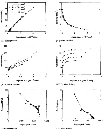
Fig. 7 Correlation between fuel injection parameters and impacts
speeds. It can be seen that, as speed increases, both the backstop and needle seat impacts become more pro- nounced. It can also be seen that, as expected, the amplitude of the needle seat impact is larger than its equivalent backstop impact.
The upper portion of Fig. 6 shows the time series data representing a pair of opening and closing impacts. The lower portion depicts the Wigner-Ville time- frequency representation of this data, showing how the frequency content of the displacement data varies with time. From this figure it can be seen that the backstop (opening) impact contains considerably more high- frequency vibration than the subsequent needle seat (closing) impact. The differing amplitude and frequency content characteristics of the opening and closing impacts will give rise to differing vibration responses of the injector body.
Part D: Journal of Automobile Engineering
4.2 Injection parameter correlation
A better understanding of the correlation between the impact behaviour and the key injection process param- eters can be gained if the injection process is divided into three intervals. The initial injection interval ranging from the lift-off of the needle to its fully open position, the principle injection interval ranging from the fully open position to the onset of needle return, and the final injection interval ranging from the onset of needle return to the completely closed position. The mean injection pressures and delivery quantities correspond- ing to each
of
these intervals are referred to as initial, principal and final, respectively.The adopted three-interval approach to the study of the injection parameters offers considerable benefits. A knowledge of injection pressure and rate behaviour in
[image:8.594.98.507.46.544.2]DIESEL INJECTOR DYNAMIC MODELLING. PART 1 301
h
E
t
c
e
e!
a
a 3
23 mm3
2.5 . -0- 31 mm3
/3
-
-x--
/. . . . + . . . . 4 2 ,,3
/ /
t
2 -
1 1.5 2
Mass ratio
Q
5
v
t
p
.-
z
\
- 5
1 1.5 2
Mass ratio
(al) Initial pressure
21 I
h
G
c
2I
e
$
a
(a2) Initial delivery
Mass ratio
(bl) Principal pressure
Mass ratio
(b2) Principal delivery
1 1.5 2
Mass ratio
(cl) Final pressure
1 1.5 2
Mass ratio
(c2) Final delivery
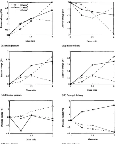
Fig. 8 Influence of needle mass on fuel injection
the defined intervals can be used in the prediction of engine performance and emissions output, because these parameters have great influence upon fuel spray pat- terns and consequent combustion quality (1,2).
In this study, the opening and closing impacts have been characterized according to the injection parameter information that they are likely to contain. The opening impact occurs at the transition between the initial and principal injection intervals, whereas the closing impact occurs at the end of the final interval. The opening impacts have thus been characterized in two ways, by using the peak value of the first collision, and the root mean square (r.m.s.) value of the collision series. Con- versely, the closing impacts have been characterized solely by the peak of the first collision.
Q IMechE 1996
Figure 7 summarizes the model-predicted behaviour for the range of engine speeds. It shows plots of pressure and fuelling against impact response for each of the three injection intervals. A line on a given plot is com- prised of four data points corresponding to the four fuel settings.
For the initial injection interval, a clear correlation between the impact peak vibration and both the pres- sure and the fuel delivery can be seen. These relation- ships are shown to remain stable with varying engine speed. From this model-predicted behaviour, it appears that the peak amplitude of the first needle opening colli- sion can be used to estimate the initial pressure and the initial delivery regardless of fuelling level and engine speed.
[image:9.594.95.503.51.556.2]302 F GU AND A D BALL
Unlike the initial interval, the predicted vibration behaviour in the principal injection interval is seen to have a dependency upon fuelling level and engine speed. Estimation of the principal pressure and fuelling from vibration response must thus take into account the fuel- ling level and speed of the engine.
Of the three injection intervals, the results for the final interval are the poorest. Nevertheless, the model- predicted peak vibration response in the final injection interval can be seen to exhibit an inverse relationship with both the pressure and fuelling.
5 THE INFLUENCE OF DIRECT MEASUREMENT TECHNIQUES
The conventional way to measure directly the motion of an injector needle is to extend the needle by means of a rod located inside the injector spring. Clearly, this involves a considerable increase in mass to the needle, especially if the extension rod is accompanied by a directly attached transducer. The developed model enables the investigation of the effect upon the injector dynamics (and consequently upon injection pressure and rate) of increasing the needle mass. The effects of needle mass changes can be explored using the model by varying the parameter m 2 ,
Figure 8 shows the effect that changing the needle mass has upon fuel pressure and delivery for a range of fuel settings. It can be seen that as the needle mass increases, the influence upon the injection parameters gets more pronounced. Influence is evident in each of the three injection intervals, and is significantly affected by the fuelling level, This apparently random behaviour makes the compensation of the directly measured test results difficult, highlighting a weakness of the direct measurement approach.
6 SUMMARY AND CONCLUSIONS TO PART 1
A two-mass dynamic model of the needle motion in a hole-type injector has been developed, incorporating contact stiffnesses and material and fluid damping properties. This model has been found useful in the investigation of needle impact behaviour and in the correlation of predicted vibration response with key injection parameters. The model has also enabled the detrimental effects of conventional intrusive needle lift measurement to be examined.
Model-based simulation of the needle motion has revealed that the opening needle impact is of lower amplitude and contains higher frequencies than its cor- responding closing impact. As fuelling increases, the amplitudes of both the opening and closing impacts have been shown to increase. In addition, the model
reflects the decrease in time separation of an impact pair that accompanies an increase in engine speed.
The model-predicted impact response has been shown to be well correlated with key fuel injection parameters in each of the three injection phases (initial, principal and final). The primary collisions of the opening and closing impacts have been shown to reflect the fuel pressure and injection rate characteristics of the initial and final injection phases, whereas the r.m.s. values of the needle opening impact series reflect the pressure and injection rate characteristics of the prin- cipal injection phase.
The model affirms the feasibility of a non-intrusive approach to the estimation of key injection parameters, based upon the externally monitored vibration response of the injector body.
Although only in the order of a few per cent, the model reveals that the direct measurement of injector needle motion by extending the needle affects the injec- tion pressure and fuel delivery. The magnitude of these effects is shown to increase with additional needle mass, and the detail of the effects is found to vary in an irregu- lar manner with fuelling.
Part 2 of this paper details the experimental pro- cedure used in the non-intrusive estimation of key injec- tion parameters.
REFERENCES
Biirgler, L, Herzog, P. L. and Winklbofer, E. The influence of injec- tion system parameters on DIdiesel spray structure, spray ignition and combustion. Seminar on Diesel fuel injection systems, IMechE, London, 1992, pp. 75-83.
Rao, K. K. and Winterbone, D. E. Pressure rise delay characteristics of a high speed DI diesel engine with high pressue injection. Seminar on Worldwide engine emissions standards and how to meet them, IMechE, London, 1993, pp. 245-251.
3 Kasaya, M. and Abe, T. A contact-point type start of injection sensor for diesel engines. SAE paper 851585,1985, pp. 5922-5929.
4 Jhccbi, G. A. Analytical simulation of fuel injection in diesel engines, SAE paper 710568, 1971, pp. 1825-1854.
5 Sobel, D. R. and Lehrach, R. P. A hydro-mechanical simulation of diesel fuel injection systems. SAE paper 870432, 1987, pp. 2236- 2248.
6 Kegl, B., Zambsre, V. V., Cernej, A. and Dobovisek, Z. A para- metric study of fuel injection performance by calculation. Seminar on Dieseljwl injection systems, IMechE, London, 1992, pp. 65-74.
7 Matsuoka, S, Yokota, K, Kamimoto, T. and Igosbi, M. A study of fuel injection systems in diesel engines. SAE paper 760551, 1976, pp.
8 Erdmann, H. D, WOM, M. and sehimller, I(.P. Experimental and theoretical analysis of injection systems of diesel engines. IMechE Conference on Diesel engines for passenger cars and light duty vehi- cles, IMechE, London, October 1982, paper C125/82, pp. 201-205 (Mechanical Engineering Publications, London).
9 Cawley, P. and Clayton, D. L. R. A vibration technique for the measurement of contact stiffness. Mechanical Systems and Signal Processing, 1987,1(3), pp. 273-283.
1854-1862.