Jaya Sudha.K1 and Jaya Rani.G2,Mirza.Shafi Sahahsavar3
MalineniLakshmaiah Women’s Engineering College, Pulladigunta, Guntur DT, A.P
[email protected]
1and [email protected]
2,[email protected]
3186
ABSTRACTField Programmable Gate Array (FPGA) optimized random number generators (RNGs) are more resource efficient than software optimized RNGs because they can take advantage of bitwise operations and FPGA specific features. By overcoming software random number generators, here a new type of RNG called a LUT_SR RNG, which takes the advantage of bit-wise XOR operations and the ability to turn lookup tables (LUTs) into shift registers of varying lengths. This provides a good resource-quality balance compared to previous Random Number Generators (RNG). Due to the large number of random bits generated per cycle these generators can be used as a basis for generators with even higher statistical quality. Each generator is based on a binary linear recurrence, with a state-transition matrix designed to make best use of all available LUT inputs in a given architecture, the optimized generators by providing an efficient method for engineers to instantiate an RNG that meets the specific needs of their applications. My proposal is, as compared to previous random number generators LUT-SR random number generator will achieves minimum delay and long period using minimal logic blocks. By designing the recurrence matrix to make maximum use of LUT inputs, it will be possible to make high quality random number generators with relatively few resources. A key advantage of the LUT-SR generators over previous optimized uniform RNG‟s is that they can be reconstructed using a simple algorithm this allow FPGA engineers to use the new RNG‟s without needing to find generator instances themselves.
I.INTRODUCTION
RANDON NUMBER GENERATORS:
Random organization is a true random number service that generates randomness via atmospheric noise. Random numbers are useful for a variety of purposes, such as generating data encryption keys, simulating and modeling complex phenomena, for selecting random samples from larger data sets and ever popular for games and gambling. When discussing single numbers, a random number is one that is drawn from a set of possible values, each of which is equally probable, that means uniform distribution. When discussing a sequence of random numbers, each number drawn must be statistically independent of the others. With the advent of computers, programmers recognized the need for a means of introducing randomness into a computer program. However, surprising as it may seem, it is difficult to get a computer to do something by chance. A computer follows its instructions blindly and is therefore completely predictable.
There are two main approaches to generating random numbers using a computer: Pseudo-Random Number Generators (PRNGs) and True Random Number Generators (TRNGs). The approaches have quite different characteristics and each has its pros and cons.
Pseudo-Random Number Generators (PRNGs): As
the word „pseudo‟ suggests, pseudo-random numbers are not random in the way you might expect. PRNGs are algorithms that use mathematical formulae or simply precalculated tables to produce sequences of numbers that appear random. PRNGs are efficient, meaning they
can Produce numbers in a short time,
and deterministic.Theseare periodic, which means that the sequence will eventually repeat itself. Popular
examples of
Such applications are simulation and modeling applications. PRNGs are not suitable for applications where it is important that the numbers are really
unpredictable, such as data encryption and
gambling.truerandom number generators (trngs): trngs extract randomnessfrom physical phenomena and introduce it into a computer. Regardless of which physical phenomenon is used, the process of generating true random numbers involves identifying little, unpredictable changes in the data. the characteristics of trngs are quite different from prngs. first, trngs are generally rather inefficient compared to prngs, taking considerably longer time to produce numbers. they are also nondeterministic, meaning that a given sequence of numbers cannot be reproduced, although the same sequence may of course occur several times by chance. TRNGs have no period.
Applications of RNGs:
Lotteries and Draws Games and Gambling
Random Sampling (e.g., drug screening) Simulation and Modeling
Security (e.g., generation of data encryption keys) In particular, uniform random bits are extremely cheap to generate in an FPGA, as large numbers of bits can be generated per cycle at high clock rates using lookup tables [1], or first-in-first-out (FIFO) queues [2]. In addition, these generators can becustomized to meet the exact requirements of the application, both in terms of the number of bits required per cycle, and for the FPGA architecture of the target on platform.
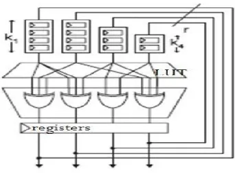
The most common FPGA architecture consists of an array of logic blocks called Configurable Logic Block (CLB) or Logic Array Block (LAB). In general, a logic block (CLB or LAB) consists of a few logical cells (called ALM, LE, Slice etc.). A typical cell consists of a 4-input LUT, a Full adder (FA) and a D-type IP- OP, as shown Figure 1.1.
Figure1.1 Basic architecture of FPGA
The LUTs are in this Figure split into two 3-input LUTs. In normal mode those are combined into a4-input LUT through the left multiplexer. In arithmetic mode, their outputs are fed to the Full Adder (FA). The selection of mode is programmed into the middle multiplexer. The output can be either synchronous or asynchronous, depending on the programming of the multiplexer to the right, in the Figure 1.1. In practice, entire or parts of the FA are put as functions into the LUTs in order to save space. Specifically, it shows how to create a family of generators called LUT-SR RNGs,which use LUTs as shift registers to achieve high quality and long periods, while requiring very few resources.
. The main contributions of this paper are as follows: LUT-based shift register (SR) is a type ofFPGA random
number generator with period of 21024-1 using two LUTs
and flip flops pregenerated random bit.
II. LUT-OPTIMIZED (LUT-OPT) RNGs
LUT-OPT generators is one of the family of generators in LUT-OPT a matrix A where each row and column contains t-1 or t 1s.it means in hardware each row maps to a t-1 or t input XOR gate, and so can be implemented in a single t input LUT, each bit of the new vector state can be calculated in a single LUT.The basic structure of a LUT-OPT generator is shown in Fig.2.2.
A simple example of a maximum period
LUT-OPTgenerator with r = 6 and t = 3
0 0 1 1 0 0 0 0 1 1 0 1 0 0 1 1 0 0 1 0 0 0 1 0 1 0 0 0 1 0 1 0 0 1 0 0 , 𝑥𝑖+1,1 𝑥𝑖+1,2 𝑥𝑖+1,3 𝑥𝑖+1,4 𝑥𝑖+1,5 𝑥𝑖+1,6 = 𝑥𝑖,3 ⊕xi,4 𝑥𝑖,3⊕xi,4⊕xi,6 𝑥𝑖,3 ⊕xi,4 𝑥𝑖,1⊕xi,5 𝑥𝑖,1⊕xi,5 𝑥𝑖,1⊕xi,4
LUT-OPT generators have two key advantages.
1) Resource efficiency: Each additional bit requires one additional LUT and FF, so resource usage scales linearly, and generating r bits per cycle requires r LUT-FFs.
2) Performance: The critical path in terms of logic is a single LUT delay, so the generators are extremely fast, so usually the clock net is the limiting factor, with routing delay and congestion only becoming a factor for large n.
However, these advantages are countered by a number of disadvantages.
1) Complexity: Each (r, t) combination requires a unique matrix of connections, which must be found using specialized software. If these matrices are randomly constructed (as in previous work), then it is difficult to compactly encode these matrices, so it is difficult for FPGA engineers to make use of the RNGs. 2) Quality: The random bits are formed as a linear combination of random bits produced in the previous cycle when t = 3, some of the new bits will be a simple two input XOR of bits from the previous cycle. The impact of this lag-1 linear dependence is minimal in modern FPGAs where t ≥ 5, and also diminishes quickly as r is increased, but remains a source of concern. 3) Period: In order to achieve a period of 2n − 1, it is necessary to choose r = n, even if far fewer than n bits are needed per cycle. An absolute minimum safe period for a hardware generator is 264 − 1, but it is preferable to have much larger periods of 21000 − 1 or more.
4) Seeding: It is necessary to initialize RNGs with a chosen state at run time, so that different hardware instances of the same RNG algorithm will generate different random streams. In a LUT-optimized generator, it is possible to implement serial loading of state using one LUT input per RNG bit to select between RNG and load mode, but in practice, for a randomly chosen matrix A, only parallel loading is possible.
188
2.2 CIRCUIT DIAGRAM OF LUT –OPT RNGIII. LUT-FIFO RNGS
To remove the quality and period problems is provided by LUT -FIFO generators [2]. These augment the 'r' bits of state held in FF's with an additional depth-k width-w first-in-first-out (FIFO), for a total period of 2n− 1, where n = r + wk, shown in Fig. 2. LUT-FIFO generators can provide long periods such as 211213− 1 and 219937− 1, but also have the following disadvantages. The word wise granularity of block-RAM-based FIFOs reduces the flexibility in the choice of r, as it can only be varied in multiples of k.
These are mild disadvantages when compared to the quality and period problems of LUT-optimized generators that have been eliminated, but LUT-FIFO generators also make the problems of complexity and efficient initialization slightly worse.
3.1BLOCK DIAGRAM OF LUT-FIFO RNG
3.2 CIRCUIT DIGRAM FOR LUT-FIFO RNG
IV. LUT-SHIFT REGISTER RNG
However, while the FIFO in a LUT-FIFO RNG is usually an expensive block RAM, LUT-based shift registers are very cheapalmost as cheap as the LUTs used to build the XOR gates. So it now becomes economical to user shift registers, one per output bit. It might be tempting to simply configure all shift registers with the same length, in an attempt to maximize the period for a given number of resources, but this cannot provide a maximum period generator. Instead, it would result in 1 + k independent r -bit generators, with a sample taken from each on successive cycles, shown in Fig 4.2. In LUT-FIFO generators, this problem is avoided by making each new output bit dependent on one bit from the previous cycle, with the remaining t − 1 or t − 2 bits provided by the FIFO output. This lag-1 dependency is not ideal, but is generally benign as the LUT-FIFO uses deep block-RAM-based FIFOs. In defining the LUT-SR generators, the provision of a serial load chain is explicitly taken into account, by embedding a chosen cycle into the matrix A from the start.
4.1 BLOCK DIAGRAM OF LUT-SR RNG
Including such a simple cycle in the generators could cause statistical problems for generators when t = 3, as there will be a simple linear dependence between adjacent output bits in cycles at a fixed lag. In an attempt to minimize this effect, an output permutation can be applied, to mix up the bits.
V. ALGORITHM FOR DESCRIBING LUT_SR GENERATORS
The LUT-SR generator family uses a short but precise algorithm for expanding a tuple of five Integersinto the full RNG structure.
The broad class of LUT-SR generators as described is very general, and it is possible to construct a huge number of candidate LUT-SR RNGs by randomly generating binary matrices that meet the requirements. LUT-SR generator family uses a short but precise algorithm for expanding a tuple of +ve integers into the full RNG structure.
TheAlgorithm takes as input a 5-tuple (n, r, t, k, and s). n=Number of state bits in the RNG (period is 2n 1). r=Number of random output bits generated per cycle. t=XOR gate input count.
k=Maximum shift register length.
s=Free parameter used to select a specie c
generator.
4.2 CIRCUIT DIAGRAM FOR LUT_SR RNG The first four parameters (n, r, t, k) describe the properties of the generator in terms of application requirements and architectural restrictions. The final parameters is used to select from amongst one of 232 candidates that the algorithm can produce with the chosen values of (n, r, t, k). Values of 's' will not result in a valid RNG, as the choice of 's' is critically dependent on (n, r, t, k), andmodifying one or more components will break the generator.
The constructor expands the RNG using five stages. 1. Create Initial Seed Cycle: A cycle of length r is
created through the r XOR gates at the output of the RNG. At this stage there are no FIFO bits, or equivalently there are r FIFOs of length 0. 2. FIFO Extension: the cycle is randomly extended
until a total cycle length of n is reached, by randomly selecting a FIFO and increasing its length by 1, while maintaining the known cycle. 3. Add Loading Connections: the known cycle is
added to the graph taps, which describes the matrix A. The cycle describes the FIFO connections completely, and also describes the first input to each of the r XOR gates.
4. Add XOR Connections: the cycle provides one input for each of the XOR gates, so now the additional t 1 random inputs are added over t 1 rounds. Each round is constructed from a permutation of the FIFO outputs, which ensures that at the end each FIFO output is used at most t times. Some bits will be assigned the same FIFO bit in multiple rounds, and so will have fewer than t inputs: this is critical to achieve a maximum period generator, and also provides us with an entry point into the cycle for seed loading.
5. Output Permutation: the simple dependency between 6. Adjacentbits is masked using a final output
permutation.
VI.SIMULATION RESULTS FOR RNG’S: 6.1 LUT-Optimized RNG:
Figure 6.1: LUT Optimized RNG
The above Figure 6.1 is the simulation result of LUT-Optimized RNG, here only 11 random numbers are generated because the outputs are directly connected to the Xor gates where the continuously Xor operations are performed, so the random numbers are generated repeatedly see Figure 6.1. Initially the input is taken from the matrix where each row and column contains t 1 or t 10 s. The usage of number of LUTs, slices, ip- ops as shown in Table6.1.
Logic Utilization Used Available
Number of Slice Flip Flops 9 3840
Number of 4 input LUTs 18 3849
Number of occupied Slices 11 1920
Table 6.1: Device utilization of LUT Optimized RNG
6.2
LUT FIRST-IN-FIRST-OUT RNGTable 6.2: Device utilization of FIFO of LUT-OPT RNGs
Logic Utilization
Used Available
Number of Slice Flip Flops
91
3840
Number of 4 input LUTs
82
3849
Number of occupied Slices
63
1920
190
Figure 6.2: Simulation result of FIFO of LUT-OPTRNGs
The figure 6.2 and 6.3 are the simulation results of LUT-FIFO RNG. where the maximum period is achieved with respect to Figure 4.2 there the output is feedback through the FIFOs, each FIFO is 2-bit length and the output is total 8-bit length, first 2-bit is send through the FIFO and remaining 6bits is send directly to Xor gates but in Figure 6.4 the same 17 number is repeated between the desired period, so advanced and accurate LUT-SR RNG is constructed.
Figure 6.3: comparison result of FIFO of LUT-OPT RNGs
6.2
LUT-SR RNG
Figure 6.4: Simulation result of LUT-SR
RNG
Figure 6.5: Comparison result of LUT-SR
RNG.
The figures 6.4 and 6.5 are the simulations results of LUT-SR RNG with respect to figure 4.2 there the output is feedback to different lengths of FIFOs to get the accurate result. Using different length of FIFOs the generated total output is not stored at same time it will store with respect to depth of FIFOs.
Example: The output bits is 01010101, where these 8-bits can be divided in to four 2-8-bits each 2-bit can be transferred to FIFO at every clock cycle present sate and previous state bits are combined and new 8-bit is generated. In figure 6.5 the starting number is 85 the same number can be get again at 13,000 ns. So using this method we achieve the maximum period and also delay is reduced as shown in table 6.5
Table 6.3: Device utilization of LUT-SR RNG Number
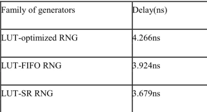
Table 6.4: Delay comparison of family of RNGs The Table 6.4 shows that delay of the family of Random Generators (RNGs), compared to LUT-optimized and LUT-FIFO RNGs the delay is less in LUT-SR RNG because the usage of logic blocks are reduced with respect to LUT-optimized RNG and LUT-FIFO RNG
Family of generators Delay(ns)
LUT-optimized RNG 4.266ns
LUT-FIFO RNG 3.924ns
LUT-SR RNG 3.679ns
Logic Utilization
Used Available
Number of Slice Flip Flops
87
3840
Number of 4 input LUTs
77
3849
Number of occupied Slices
59
1920
191
VII. Conclusion:Here a family of optimized uniform Random Number Generators (RNGs) are constructed, these are independent shift registers which allowing high quality long-period generators using only a small amount of logic. A key advantage of the LUT-SR generators over previous optimized uniform RNGs is that they can be reconstructed using a simple algo-rithm this allows FPGA engineers to use the new RNGs without needing to nd generator instances themselves.
As compared through previous random number generators the LUT-SR random num-ber generator achieves minimum delay and long period using minimu logic blocks. By designing the recurrence matrix to make maximum use of LUT inputs, it is possible to make high quality random number generators with relatively few resources.
REFERENCES
[1] The LUT-SR Family of Uniform Random Number Generators for FPGA ArchitecturesDavid B. Thomas, Member, IEEE, and Wayne Luk, Fellow, IEEE.VLSI SYSTEMS, VOL. 21, NO. 4, APRIL 2013
[2] D. B. Thomas and W. Luk, “High quality uniform random number generation using LUT Optimized state-transition matrices,” J. VLSI Signal Process., vol. 47, no. 1, pp. 77– 92,
2007.
[3] D. B. Thomas and W. Luk, “FPGA-optimized
high-quality uniform random number
Generators,” in Proc. Field Program. Logic Appl. Int. Conf., 2008, pp. 235–244.
[4] P. L‟Ecuyer, “Tables of maximally equidistributed combined LFSR generators,” Math. Comput., vol. 68, no. 225, pp. 261–269, 1999.
[5] D. B. Thomas and W. Luk, “FPGA-optimized uniform random number generators using luts and shift registers,” in Proc. Int. Conf. Field Program. Logic Appl., 2010, pp. 77– 82. [6] M. Matsumoto and T. Nishimura, “Mersenne twister: A 623-dimensionally equidistributed uniform pseudo-random numbergenerator,”ACM Trans. ModelingComputer.Simulator.vol. 8, no. 1, pp. 3–30Jan. 1998.
[7] M. Saito and M. Matsumoto, “SIMD-oriented fast mersenne twister: A 128-bit Pseudorandom number generator,” in Monte-Carlo and Quasi-Monte Carlo Methods. New York: Springer-Verilog, 2006, pp.
607–622.Matsumoto, “Improved long-period
generators based On linear recurrences modulo 2,” ACM Trans. Math. Software, vol. 32, no. 1, pp. 1– 16,
2006. .
Bibliography:
1Kamatham Jaya Sudha is pursuing her M.Tech in MLWEC Pulladigunta Guntur A. P under JNTUK University
.Her area of interest is VLSI.
2G.Jaya Rani has completed her Bachelors in V.R Siddartha college of Engineering under affiliation of
AcharyaNagarjuna University in the stream of Electronics and Communication. M.Tech in Digital Systems and Computer Electronics from JNTUH.Her area of interests are VLSI and Computer Electronics.
3Miraza. ShafiShahsavar has done his Bachelors in Karnataka University in the stream of ECE and M.E in
University of Western Ontario in the stream of Wireless Communication in VLSI. Pursuing PhD in KL University .His area of interests is Wireless Communication, Signal Processing