a
Corresponding author: [email protected]
Influence of low-specific speed pump modifications on stability of Y-Q
curve
Roman Klas1,a)UDQWLãHN3RFK\Oê1 and Pavel Rudolf1
1
Brno University of Technology, Faculty of Mechanical Engineering, Victor Kaplan Department of Fluids Engineering, Technická 2, 61669 Brno, Czech Republic
Abstract. Contribution is focused on modification of low-specific speed pump impellers with respect to stability of their Y-Q curves (i.e. head curves). The design modifications are driven by analysis of the dissipated power. First, dissipated power is evaluated by CFD software in individual working parts of the pump and then its dependence on flow rate is investigated. Pressure fields within the pump are also carefully examined. Special attention is paid to impellers and configuration of the blade channels and recirculating channels. Results point to significant influence of the proper inflow to recirculating channels and also to role of the volute, which is more pronounced than in conventional impellers. All integral characteristics from CFD simulations are verified experimentally.
1 Introduction
The low specific speed centrifugal pumps are known for their low hydraulic efficiency. The reason is usually ascribed to secondary flow in blade channels of impellers, where so called local eddy develops. This phenomenon causes increased losses due to recirculation and also higher streamline curvature at the impeller outlet, resulting in a significant decrease of the angle at which the liquid leaves the impeller (viewed in relative rotating space). This deviation from the blade outlet angle poses reduction of attainable delivery head or specific energy [1, 2].
Operating characteristics of the centrifugal pumps may show signs of instability, which may significantly affect the possibilities of their use. The specific energy curves used to be fundamental from this point of view. The instability can be detected or the problems with the pulsation of the static pressure and noise of the machine can be predicted on the base of these curves.
Above mentioned problems are often solved issue and it is therefore very important to identify the main causes of the instability. Their design of course varies according to the operating parameters of each pump. The main attention in this paper is focused on the low specific speed centrifugal pump. Investigated pump will be equipped with a conventional impeller with thin blades and a new impeller with thick trailing edges. As a basic tool for the analysis CFD simulations will be employed. Wherever it is possible the results from the CFD analysis are compared to the data obtained from the experiment [3].
2 Main parameters and computational
mode of CFD simulations
ns = 3.65 n Q0.5 H-0.75
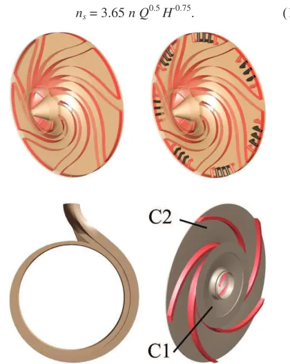
Figure 1. Impellers with thick trailing edges and with / without recirculation channels, spiral case and conventional impeller.
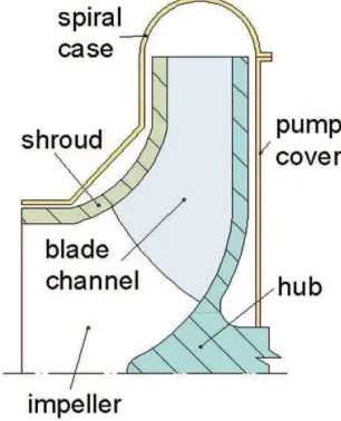
! ! " #
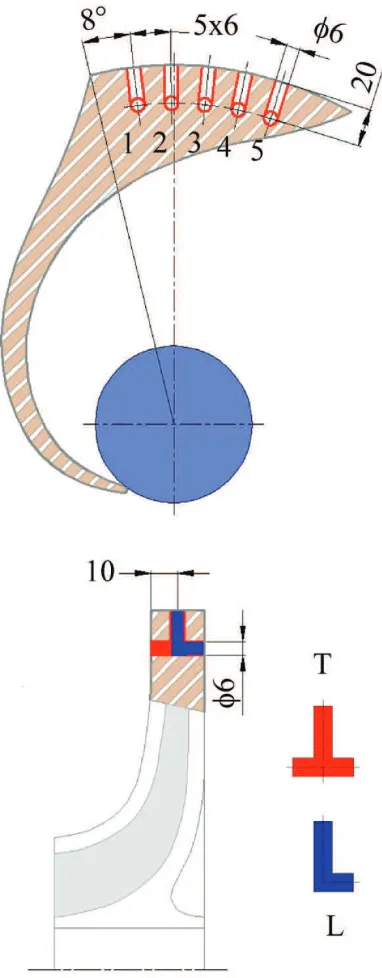
Figure 2. Blade-to-blade view and meridional section of the pump.
$! ! " !% $&'(' ! )*+ , -$./0 ")1 %
/
2 3
"
2 04
3
04 35
#5 * +
ȕ"6±
7" 17
%"± 87"8
95± 1:)
(;4 5±
7)
5±
")1+
5±
77
&
"±7
#4±İ
/ 0<
3
Dissipation power
=
2 >)? "
w w
"
@ "%@ 7. >*?
w w ! w w
/ % )
³³³
Ș )@ A
ݒ !%
. % A A !% # * $ 5 >1? 7 !%
¦
¦
*4
Main characteristics
!% ! ! 7 A Figure 3. The specific energy curves obtained from
experimental testing and from CFD simulations.
0 $ 35 5 0 5 4 . ! ) $ A
@ ! ) A
A # ! . HYDOXDWLRQ LV DFFRUGLQJ WR YDOLG VWDQGDUG ý61 (1 ,62 ::81
@ A A 4 $ ! 4 ! *
Figure 4. Dissipation power in the pump.
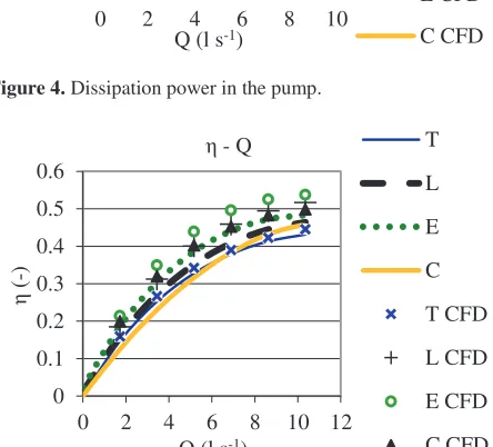
Figure 5. The curves of hydraulic efficiency (CFD) and total efficiency (experiment) in the pump.
250 270 290 310 330 350
0 2 4 6 8 10 12
Y (J
k
g
-1)
Q (l s-1)
Y - Q T
L E C T CFD L CFD E CFD C CFD 250 1250 2250 3250 4250 5250
0 2 4 6 8 10
2D
H
(W)
Q (l s-1)
2D - Q, 2DH - Q T
L E C T CFD L CFD E CFD C CFD 0 0.1 0.2 0.3 0.4 0.5 0.6
0 2 4 6 8 10 12
Ș
(-)
Q (l s-1)
Ș - Q T
5
Analysis of pump interior
0
' @ 7. ! 1
Figure 6. Meridional section of the pump.
! ! + 4 ! 4 4 35 ! + B >+? ! C
Figure 7. Dissipation power in the spiral case.
0 7 /
4
! ! 4 " A ! : # (59
Figure 8. Dissipation power in blade channels.
Figure 9. Dissipation power in the gap between the hub and cover of the pump.
Figure 10. Dissipation power in the gap between the shroud and stator of the pump.
250 750 1250 1750 2250
0 2 4 6 8 10
2D
H
(W)
Q (l s-1)
2DH - Q T
CFD
L CFD
E CFD
C CFD
0 200 400 600 800 1000
0 2 4 6 8 10
2D
H
(W)
Q (l s-1)
2DH - Q T
CFD
L CFD
E CFD
C CFD
0 200 400 600 800 1000
0 2 4 6 8 10
2D
H
(W)
Q (l s-1)
2DH - Q T
CFD
L CFD
E CFD
C1 CFD
C2 CFD
0 100 200 300 400
0 2 4 6 8 10
2D
H
(W)
Q (l s-1)
2DH - Q T
CFD
L CFD
E CFD
! 8 4 35 5
6
Pressure pulsations within the pump
/ # ! ! " $ 5 !%Figure 11. Static pressure pulsation in the whole pump interior close to the shut-off point.
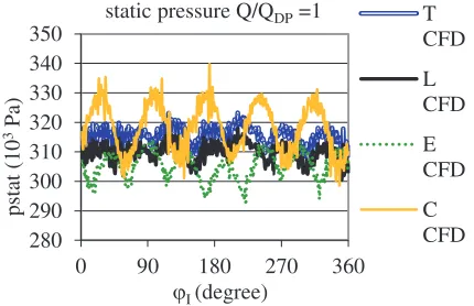
Figure 12. Static pressure pulsation in the whole pump interior close to the best efficiency point.
5 50 4 4
!
A >C :?
!%
7
Conclusions
/ 4 4
5 5 @ < 35 @ B 4 $ 5
4
4
D 4 < 5 4 #
'
References
1. J. F. Gülich, Centrifugal Pumps (Heidelberg Springer-Verlag, 2010)
2. C. E. Brennen, Hydrodynamics of Pumps (New York: Oxford University Press, 1994)
3. Y. Meng, Ch. Li, H. Yan, X. Liu, Proc. Int. Conf. on Computer Eng. and Aplications (Manila), 2, pp 179-183 (2009)
4. J. F. Gülich, U. Bolleter, ASME J Vib Acoust, 114, 272-9 (1992)
5. F. Pochylý, M. Haluza, S. Drábková, Engineering Mechanics 2009 ± book of extended abstract, 208-215 (2009)
6. H. Benigni, H. Jaberg, H. Yeung, J. Fluids Eng.134 024501-4 (2012)
7. Y. W. Wong, W. K. Chan, W. Hu, Artificial Organs, 31(8), 639-645 (2007)
8. G. Schaefer, E. Olson, Journal of World Pumps Issue 393 pp 34-37 (1999)
300 330 360 390
0 180 360 540 720
pstat (10
3 Pa
)
MI (degree)
static pressure Q/QDP =0.25 T CFD
L CFD
E CFD
C CFD
280 290 300 310 320 330 340 350
0 90 180 270 360
pstat (10
3 Pa
)
MI (degree)
static pressure Q/QDP =1 T CFD
L CFD
E CFD
9. V. Godbole, R. Patil, S. Gavade, 15th Int. Conf. Experimental Mechanics (Porto) Paper ref: 2977 pp 1 -14 (2012)
Acknowledgement
3URMHFW &= ³3RGSRUD WYRUE\ H[FHOHQWQtFKWêPĤPH]LRERURYpKRYê]NXPXQD987´LV gratefully acknowledged for support of this research.