c
Owned by the authors, published by EDP Sciences, 2015
Recent progress on HYSPEC, and its polarization analysis capabilities
Barry Winn1,a, Uwe Filges2, V. Ovidiu Garlea1, Melissa Graves-Brook3, Mark Hagen4,5, Chenyang Jiang3, Michel Kenzelmann2, Larry Passell6, Stephen M. Shapiro6, Xin Tong3and Igor Zaliznyak6
1Oak Ridge National Laboratory, Quantum Condensed Matter Division, Oak Ridge, USA 2Paul Scherrer Institut, Laboratory for Developments & Methods, Villigen PSI, Switzerland 3Oak Ridge National Laboratory, Instrument and Source Division, Oak Ridge, USA 4Oak Ridge National Laboratory, Neutron Data Analysis & Visualization, Oak Ridge, USA 5European Spallation Source, Data Management and Software, Copenhagen, Denmark
6Brookhaven National Laboratory, Condensed Matter Physics & Materials Science Department, Upton, USA
Abstract. HYSPEC is a high-intensity, direct-geometry time-of-flight spectrometer at the Spallation Neutron Source, optimized for measurement of excitations in small single-crystal specimens with optional polarization analysis capabilities. The incident neutron beam is monochromated using a Fermi chopper with short, straight blades, and is then vertically focused by Bragg scattering onto the sample position by either a highly oriented pyrolitic graphite (unpolarized) or a Heusler (polarized) crystal array. Neutrons are detected by a bank of3He tubes that can be positioned over a wide range of scattering angles about the
sample axis. HYSPEC entered the user program in February 2013 for unpolarized experiments, and is already experiencing a vibrant research program. Polarization analysis will be accomplished by using the Heusler crystal array to polarize the incident beam, and either a3He spin filter or a supermirror wide-angle polarization analyser to analyse the scattered beam. The3He
spin filter employs the spin-exchange optical pumping technique. A 60◦wide angle3He cell that matches the detector coverage
will be used for polarization analysis. The polarized gas in the post-sample wide angle cell is designed to be periodically and automatically refreshed with an adjustable pressure of polarized gas, optically pumped in a separate cell and then transferred to the wide angle cell. The supermirror analyser has 960 supermirror polarizers distributed over 60◦, and has been characterized at the Swiss Spallation Neutron Source. The current status of the instrument and the development of its polarization analysis capabilities are presented.
1. Introduction
HYSPEC is a high-intensity, medium-resolution, cold to thermal direct geometry chopper spectrometer (DGS) optimized for inelastic neutron scattering measurements of excitations in small single-crystal specimens [1,2]. Short for “hybrid spectrometer”, HYSPEC employs a hybrid design by adding to a traditional time-of-flight spectrometer the pre-sample Bragg focusing optics found on a triple-axis spectrometer (TAX). The combination of Fermi chopper, Bragg focusing optics, and movable detector bank, leads to a highly versatile instrument in which the energy resolution can be independently varied by nearly an order of magnitude. Also, HYSPEC by design is capable of changing configurations from unpolarized neutron scattering to polarized neutron scattering.
2. Design choices
HYSPEC is located after a coupled cryogenic H2 (c-1H) moderator at beam port 14B at the Spallation Neutron Source (SNS) at Oak Ridge National Laboratory. The layout is shown in Fig.1.
The Fermi chopper is HYSPEC’s true monochromator, setting the energy of the incident beam (Ei) between
aCorresponding author:[email protected]
3.8 and 60 meV by choosing the appropriate phase of the chopper opening, and trading off between flux and resolution by changing rotation frequency between 30 Hz and 420 Hz in 30 Hz increments. At 37.17 m from the moderator, it has straight blades 10 mm long with 0.6 mm slits as shown in Fig. 1, so at 180 Hz the burst time of the Fermi chopper is 50µs. The Fermi chopper is usually operated between 180 Hz and 420 Hz, providing an elastic line resolution full width at half maximum (FWHM) of 2.3–10% of Ei. Information about the chopper timing is integrated into the neutron data stream to allow for later filtering of pulses.
A vertical rotation axis T0 chopper at 8.5 m and a curved guide between 9.9 m and 34.0 m both reject the highest energy neutrons. The curved guide occludes direct line-of-sight for even the glass portion of the guide, and employs steel cladding that is attached to the supermirror glass substrate. The steel cladding is stepped on the outside to reduce shine, and both steel bricks and woven fiberglass bags containing either steel beads or polyethylene beads are packed between the steel cladding and the surrounding concrete shielding.
Other choppers and the drum shield reduce background from unwanted cold and thermal neutrons. The disc chopper at 9.4 m rejects frame overlap neutrons with energies above 30µeV. The disk chopper at 36.5 m rejects
Figure 1. HYSPEC’s layout, Fermi chopper rotation package, and Bragg vertical focusing arrays. Some concrete shielding is removed to make the guide and chopper housings visible. The top and side walls of the detector vessel are removed to enable viewing of the detector array. An optional spin-exchange optical pumping, and gas transfer cart is shown attached to the side of the detector vessel.
neutrons that would have been transmitted by the Fermi chopper running at frequencies higher than 60 Hz. Finally, the drum shield that houses the Bragg optics also serves as a beam stop for neutrons not diffracted towards the sample. The supermirror guide coatings are m=3.0, except the inner curved surface of the curved section which is m=2.0. Between moderator and T0 chopper, a trumpet geometry increases guide height from 130 mm to 150 mm, to preserve intensity and reduce vertical divergence for the vertically focusing Bragg optics.
After the Fermi chopper sets Eiand energy resolution, Bragg optics vertically focus the neutron beam from a 40 mm wide, 150 mm tall guide, onto the sample. The Bragg optics to sample distance can be adjusted between 1.8 mm and 1.4 m. Both Bragg optics and drum shield are positioned to satisfy the Bragg condition. As the drum shield rotates, it also moves a cantilevered sample and air-pad based detector vessel, which are shown in Fig. 2. In order to change between an unpolarized and a polarized incident beam, an elevator inside the drum shield moves into the beam either a highly oriented pyrolitic graphite (HOPG) array or a magnetically yoked Heusler array, respectively; both arrays are shown in Fig. 1. Although the configuration of the Bragg optics with drum shield is reminiscent of a monochromator of a TAX, the Fermi chopper sets the energy resolution. The HOPG has a 1.2◦ FWHM mosaic, while the Heusler array has a 0.5◦FWHM mosaic. Both crystal arrays may also be operated without vertical focusing (i.e. flat).
The incident beam profile is defined using two sets of motorized slits between drum shield and sample that
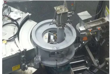
Figure 2. Photograph of the HYSPEC secondary spectrometer. From left to right are: the drum shield housing the Bragg focusing arrays, a furnace at sample position, and the detector vessel.
are mounted on an optic rail attached to the drum shield. The incident beam horizontal divergence may be further defined using 20or 40S¨oller collimators.
scattering from a 6 mm diameter vanadium rod would be centered at 0 meV.
The distance from the moderator to sample is ≈40.8 m. HYSPEC employs tail-mounted sample envi-ronments in air, on a multi-axis stage that includes tilt stages, translation stages, and a vertical axis rotation stage. This configuration, common to triple axis spectrometers, enables orientation of a desired scattering plane for a single crystal or crystal array into the horizontal plane, and provides some flexibility in configuration. Removal of the multi-axis stage makes space for larger sample environments.
HYSPEC employs 3He linear position sensitive tube detectors that are assembled into 20 sets of 8-packs. The 8-packs are arrayed in a cylindrical geometry around the sample position at a ≈4.5 m radius, with the axis of the cylinder oriented vertically. The 8-packs consist of stainless steel cylindrical detector tubes with 25.4 mm diameter and 1.2 m height. The combination of 100 ns time resolution for neutron detection, the 4.5 m distance between sample and detector, and the knowledge of the Ei enables a determination of the energy transfer ω for the detected neutron. The detector bank covers an angular range of 60◦ in the horizontal scattering plane, but the entire bank can be rotated about the sample, providing measurement at scattering angles of up to +/−135◦depending upon the Eibeing used. Most 8-packs have a≈25 mm spacing between them, but between sets of 5 8-packs there is a≈50 mm gap. The total vertical acceptance of the detector bank is 15◦. When using vertical focusing and a Bragg optics to sample distance of 1.8 m, the total divergence from focusing is 4.8◦.
The HYSPEC detector vessel provides an argon flight path for scattered neutrons between 0.8 and≈4.4 m. This vessel has aluminium walls and aluminium entrance and exit windows that define the Ar-filled volume, but the 8-packs are outside and accessible. The aluminium walls are covered on the inside by 1.5 mm thick cadmium sheet to reduce background from neutrons with energies below 300 meV. The 8-packs have 1 cm thick boron carbide plates immediately behind the tubes, and are surrounded on top, bottom and back by cadmium sheet. Cadmium baffles∼45 mm long minimize scatter between adjacent 8-packs. Speed of rotation for the detector vessel about either sample or drum shield is restricted to 0.1◦/s.
Just before and attached to the detector vessel, is a fine radial collimator. The fine radial collimator overfills the detector bank acceptance, and has gadolinium oxide coated panes that span between 550 to 750 mm radii from the sample, with 40between panes. It does not oscillate with respect to the detector array.
Neutron acquisition is performed by fast electronics developed at the facility, and tied to the primary accelerator timing system. Each neutron event is recorded and timed with a 100 ns clock from a set offset to when the injection signal is sent to the kicker magnet of the accelerator. Data are streamed from the detector electronics, and each detected neutron is stored as a unique “event” which contains information about which detector tube, what position along that detector tube, the time stamp of detection, and from which pulse of the accelerator
the detected neutron originated. Collecting the data in this “event stream” mode enables maximal retention of information, and provides an efficient alternative format to mostly empty histograms for storage, loading and processing.
HYSPEC also leverages the neutron event stream via Accelerating Data Acquisition, Reduction and Analysis (ADARA) [3], which adds into the neutron event stream values for motors, chopper settings and sample environments, as well as chopper phase information and neutron monitor events, and multiplexes the combined event stream. The multiplexed event stream feeds into immediate translation for NeXus files, a live viewing of reduced data using the Mantid [4] Live Listener, and remote system monitoring and alert tools. Although first prototyped on HYSPEC, ADARA is gradually being rolled out to other instruments at the SNS.
Mantid software is used to both visualize and diagnose raw data, and to automatically reduce the raw data into instrument-independent formats readable by the analysis software packages DAVE-mslice and Horace, as well as Mantid. Reduced files are usually available mere seconds after a data acquisition run has completed. However, only Mantid can simultaneously reduce and analyse data sets with different detector-array configurations, and analyse using the event data format.
3. Unpolarized performance
At Ei=15 meV and Fermi chopper frequency of 180 Hz (corresponding to an elastic energy resolution of 5.5%), using vertically focused HOPG at 1.8 m before the sample, a gold foil measurement coupled with an image plate recording of the neutron beam profile at the sample position indicated a peak intensity, normalized to accelerator power, of 4.2×10⁵n/s/cm2/MW. The image plate recording reveals a roughly Gaussian profile with FWHM 35×35 mm2. Figure 3 shows the relative scattered flux at incident energies 3.8–60 meV from a 6 mm diameter vanadium rod, for both HOPG and Heusler focusing arrays, with a Fermi chopper frequency of 180 Hz. Dips in intensity are due to the combination of the focusing crystal’s reflectivity and Bragg scattering from upstream aluminium windows. The vanadium scatter observed has uniform intensity across the detector banks, which indicates that the fixed radial collimator is well aligned to the sample position. Scattered flux varies with the inverse of the chopper frequency. Figure 4 shows the measured energy resolution FWHM of the vanadium elastic scattering, which is the same for both Bragg focusing arrays. As with all DGS’s, energy resolution improves with energy loss.
Figure 3. Relative scattered flux measured from a 6 mm diameter vanadium rod, for both HOPG and Heusler focusing arrays, with a Fermi chopper frequency of 180 Hz. The detector vessel was positioned for a horizontal scatter range of−90◦ to −30◦ for 3.8 meV< Ei <6.8 meV, of −80◦ to −20◦ for 7.5 meV< Ei <40 meV, and of 30◦to 90◦for 40 meV<Ei<60 meV.
Figure 4. Measured energy transfer resolution FWHM atω=0 meV from a 6 mm diameter vanadium rod, using the HOPG array, at Fermi chopper frequencies 180, 300 and 420 Hz.
background, its count rate remains at ∼10 counts per second distributed throughout our detector array, which can be comparable to some inelastic features. Partial time-dependent contributions to this feature make simple “empty-can” subtraction problematic. The time-of-flight window for energy gain and loss overlaps with this feature for some Ei’s, leading to the restricted Eiranges.
4. User program
HYSPEC entered the SNS user program in February of 2013 using unpolarized neutrons. Two of these experiments have already resulted in publications [5,6], and many more are in preparation. Prospective users who are unsure which DGS at the SNS is best suited for their experiments are referred to a recent comparison paper [7]. Table 1 lists sample environments that have been used at HYSPEC to date, but other sample environments are already, or will be, available.
The “hybrid” aspects of HYSPEC lead to a slightly different approach towards performing experiments, than at a conventional DGS. Experiments with single crystals are limited to measuring very little outside a single plane of scattering, because the vertical detector array acceptance is limited, and vertical focusing causes a partial filling of that acceptance. Users are encouraged to align a single crystal prior to their experiment, so that the scattering plane
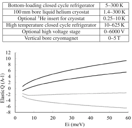
Table 1. Sample environments used at HYSPEC by June 2014.
Bottom-loading closed cycle refrigerator 5–300 K 100 mm bore liquid helium cryostat 1.4–300 K
Optional3He insert for cryostat 0.25–10 K
High temperature closed cycle refrigerator 10–625 K Optional high voltage stage 0–6000 V Vertical bore cryomagnet 0–5 T
Figure 5. Elastic momentum transfer Q range available as a function of Eiusing the HOPG focusing array. The solid curves
correspond to the left-most and right-most detector tubes with the detector array rotated as far left as possible for the given Ei, while
the dotted curves correspond to the same detector tubes with the detector array rotated as far right as possible.
of interest lies in the horizontal plane. Vertical focusing relaxes the vertical Q resolution so reduction involves an integration of the scattered intensity over part of the detector height. Final single crystal alignment is performed with a monochromatic beam, using a process very similar to alignment at a TAX. Finally, the highest achievable elastic momentum transfer magnitude Q depends on both the Ei and the space available on the tanzboden (see Fig.5), which again is similar to the situation found at a TAX.
Other aspects of HYSPEC distinguish it from TAX’s. During alignment, it is common to attenuate the incident beam using thin B-10 loaded aluminium, in order to reduce the count rate on a single detector to at most ∼200 c/s saturation on the detectors when measuring Bragg peaks (the 3He detector tubes saturate at such a low time-averaged count rate due to the pulsed nature of the elastically scattered neutrons). HYSPEC’s momentum-energy resolution function differs from that of a TAX, since the Fermi chopper frequency sets Ei resolution and the final energy is measured via Time of Flight. The TAX practice of reversing relative scatter direction of the pre-sample Bragg array and sample is not adhered to at HYSPEC. Instead, the detector vessel is positioned to whichever side of the incident beam will fit on the tanzboden.
orientations of the detector vessel. In a single instrument configuration, a single crystal sample is rotated about the vertical axis to populate the desired volume of ω and momentum transfer vector Q. A carefully chosen detector array orientation with HYSPEC’s angle width of 60◦ provides sufficient Q andωvolume to measure excitations of interest for most experiments. Such data sets are usually acquired at a few parameter settings (temperature, voltage, magnetic field, etc.). Finally, HYSPEC’s time-averaged flux is significantly lower than at many TAX’s, so parametric studies at a fixed energy and momentum transfer, where scattered intensity is correlated with many parameter values, are better completed at a TAX.
Although most experiments which are run at HYSPEC involve single crystals or coaligned crystal arrays, powders have also been studied [7] using vertical focusing. For inelastic spectra the detector vessel generally stays in place, but when a more detailed elastic powder diffraction measurement is needed, the detector vessel is repositioned several times within a ∼1◦ horizontal angle range, to account for physical gaps between 8-packs and angle-dependent detector tube efficiency.
5. Polarization analysis
The region around the sample position is designed to accommodate polarization analysis. The drum shield is assembled from mostly nonmagnetic materials such as stainless steel and lead. Optical components are mounted to an aluminium optic-rail, and a separate set of manual, nonmagnetic apertures replace the motorized apertures. The top surface of the sample multi-stage axis is well below beam elevation at 270 mm. The front end of the detector vessel and the radial collimator are constructed from only aluminium and titanium, with very few stainless steel fasteners.
To polarize the incident beam, the Heusler focusing array is moved into the beam. A permanent magnet yoke assembly inside the exit port of the drum shield generates a magnetic field that preserves neutron polarization between the Heusler array and the outside of the drum shield. The part of the yoke assembly at the outer radius of the drum shield was modified to weaken the magnetic field outside the drum shield to∼15 Gauss at 100 mm from the drum shield, in order to better couple to the Mezei flipper guide field. A set of optic-rail mounted variable-strength magnet yoke assemblies is positioned to tune the guide field between the drum shield and sample (see Fig.6). A Mezei flipper is used to flip the spin state of the incident neutron beam.
Several neutron analysers have been used to charac-terize the polarization of the incident beam, including a Heusler single crystal, a compact polarizing supermirror array, and several 3He cells. The detector array is positioned to measure the diffracted, reflected, or transmitted beam, respectively. Count rate was restricted to at most 200 c/s to minimize detector saturation. Using the polarizing supermirror array and Mezei flipper, the highest flipping ratio observed for the standard system (Heusler + guide fields + Mezei flipper +supermirror array) at 15 meV with a vertically focused beam was 23. A high Tc cryo-flipper loaned by the University of
Figure 6. At right is the compact polarizing supermirror array mounted at sample position to characterize the polarization of the incident beam. Also shown left to right are the optic-rail mounted Mezei flipper, one of the guide field magnet yokes, and a boron nitride fixed size aperture. These three are enclosed inside a cadmium lined incident beam shielding box, with side-walls removed.
Figure 7. The vertical axis 4-coil electromagnet is attached to the detector vessel, just before the radial collimator. The3He
cell rests in the middle of the coils, while a 127 mm diameter sample environment tail holding a bottom loading closed cycle refrigerator is mounted at the sample position 124 mm away from the coil center.
Indiana [8] was also tested, replacing the Mezei flipper, and the flipping ratio observed was 32. These results are preliminary, because further tuning and characterization of individual components are still required.
Alternatives to using the Heusler focusing array to polarize the incident beam have just begun to be explored. In these configurations, the HOPG focusing array was used to increase intensity at sample. An in-situ Spin Exchange Optical Pumping (SEOP) assembly has been tested at HYSPEC to polarize the incident beam [9]; results are still being evaluated to determine whether this system provides a better combination of transmission and polarization. Also, the same supermirror array used to characterize the incident beam polarization may be mounted on the optic rail upstream of the sample.
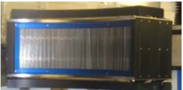
Figure 8. The wide angle polarizing supermirror array.
vertical axis Helmholtz electromagnet, centered at the3He cell instead of the sample. To maximize the lifetime of the 3He nuclei polarization the electromagnet is designed to achieve a spatial uniformity of 2.5×10⁻⁵cm−1. In order to maintain a high 3He gas polarization in the cell and optimize the polarization and transmission of the neutrons through the cell for different scattered neutron energies, the wide-angle cell will be periodically and automatically refreshed with an adjustable pressure of polarized gas. The 3He nuclei will be polarized via SEOP in a separate cell, on a cart attached to the detector vessel [10].
While the cart is being built and tested offline, several drop-in GE-180 glass cells of various shapes and 3He pressures were optically pumped in a separate SEOP station, installed in HYSPEC’s electromagnet, and used to measure the polarization of the incident beam, to test adiabatic fast passage neutron magnetic resonance flipping, and to measure the spin-incoherent scattering from vanadium. The highest system-wide flipping ratio measured for the polarization of a 15 meV incident beam using a 3He cell in direct transmission, with the Heusler vertically focused, and a pinhole mounted at sample position, was 21.8. A preliminary measurement of the 6 mm diameter vanadium rod scattered into the detector array indicates a system-wide spin incoherent scattering ratio of 1.47 at 15 meV, over a detector region≈35◦wide and≈10◦tall.
The other option for polarization analysis will employ an array of polarizing remanent supermirrors with an m=3 polarizer coating (FeCoV) on both sides, that re-places the fine radial collimator. Designed and constructed at the Paul-Scherrer Institut, the array shown in Fig. 8 has 960 supermirrors distributed over 60◦ and employs a magnetic holding field of ≈60 Gauss. Its polarization and transmission have been measured at the Beamline for Optics and other Approaches at the Swiss Spallation Neutron Source, at several angles using a “white” incident beam with energy range consistent with the 3.8–25 meV final energy range intended for this analyser. The optimum polarization was found to be above 92%, and the average transmission at the optimum polarization deflection angle was found to be 30%. An electromagnet charging station has been tested and delivered to the HYSPEC instrument.
The following people have made significant contributions to the design or commissioning of HYSPEC: D. Anderson, D. Brown, W.A. Hamilton, K. Herwig, E. Iverson, W.J. Leonhardt, S.R. Parnell, and B.M. Thibadeau. Construction of HYSPEC was funded by (U.S.) Department of Energy (DOE) grant (Grant No. DE-FG02-01ER45912). Research at SNS was sponsored by the Scientific User Facilities Division, Office of Basic Energy Sciences (BES), DOE. Work at Brookhaven National Laboratory was supported by the Materials Sciences and Engineering Division, BES under Contract No. DE-AC02-98CH10886.
References
[1] I. Zaliznyak, V. Ghosh, S.M. Shapiro, L. Passell, Physica B 356, 150 (2005)
[2] S.M. Shapiro, I.A. Zaliznyak, L. Passell, V.J. Ghosh, W.J. Leonhardt, M.E. Hagen, Physica B, 385–386, 1107 (2006)
[3] G.M. Shipman, S.I. Campbell, M. Doucet, J. Kohl, G.E. Granroth, R. Miller, D. Stansberry, Th. Proffen, R.J. Taylor, Proceedings of The 10th IEEE International Conference on e-Science (accepted)
[4] O. Arnold, J.C. Bilheux, J.M. Borreguero, A. Butsa, S.I. Campbell, L. Chapona, M. Doucet, N. Draper, R. Ferraz Leal, M.A. Gigga, V. E. Lynch, A. Markvardsen, D.J. Mikkelsone, R.L. Mikkelsone, R. Miller, K. Palmen, P. Parker, G. Passos, T.G. Perring, P.F. Peterson, S. Ren, M.A. Reuter, A.T. Savici, J. W. Taylor, R.J. Taylor, R. Tolchenov, W. Zhou, J. Zikovsky, Nucl. Instrum. Methods A, 10.1016/j.nima.2014.07.029 (2014)
[5] W. Tian, G. Tan, L. Liu, J. Zhang, B. Winn, T. Hong, J.A. Fernandez-Baca, C. Zhang, and P. Dai, Phys. Rev. B 89, 144417 (2014)
[6] D. Fobes, I.A. Zaliznyak, Z. Xu, R. Zhong, G. Gu, J.M. Tranquada, L. Harriger, D. Singh, V.O. Garlea, M. Lumsden, and B. Winn., Phys. Rev. Lett, 112, 187202 (2014)
[7] M.B. Stone, J.L. Niedziela, D.L. Abernathy, L. DeBeer-Schmitt, G. Ehlers, O. Garlea, G.E. Granroth, M. Graves-Brook, A.I. Kolesnikov, A. Podlesnyak and B. Winn, Rev. Sci. Instrum. 85, 045113 (2014)
[8] T. Wang, F. Li, S.R. Parnell, W.A. Hamilton, H. Kaiser, A.L. Washington, D.V. Baxter and R. Pynn, J. Phys.: Conf. Ser. 528 012024 (2014)
[9] C.Y. Jiang, X. Tong, D.R. Brown, S. Chi, A.D. Christianson, B.J. Kadron, L. Robertson, B.L. Winn, Rev. Sci. Instrum. 85, 075112 (2014)