Optimal Power Flow in Transmission System
by Using UPFC
MCV Suresh1, G Hanumantha Reddy2
Assistant Professor, Dept. of EEE, S V College of Engineering, Tirupati, India1
Assistant Professor, Dept. of EEE, S V Engineering College for Women, Tirupati, India 2
ABSTRACT: Controlling power flow in modern power systems can be made more flexible by the use of recent developments in power electronic and computing control technology. The Unified Power Flow Controller (UPFC) is a Flexible AC transmission system (FACTS) device that can control all the three system variables namely line reactance, magnitude and phase angle difference of voltage across the line. The UPFC provides a promising means to control power flow in modern power systems. Essentially the performance depends on proper control setting achievable through a power flow analysis program.
The paper presents a reliable method to meet the requirements by developing a Newton-Raphson based load flow calculation through which control settings of UPFC can be determined for the pre-specified power flow between the lines. The proposed method keeps Newton-Raphson Load Flow (NRLF) algorithm intact and needs (little modification in the Jacobian matrix). A MATLAB program has been developed to calculate the control settings of UPFC and the power flow between the lines after the load flow is converged.
Case studies have been performed on IEEE 5-bus system to show that the proposed method is effective. These studies indicate that the method maintains the basic NRLF properties such as fast computational speed, high degree of accuracy and good convergence rate.
KEYWORDS: UPFC; FACTS (Statcom, TCSC, TCRP); optimal power flow algorithm (N-R Method); Mat lab.
I. INTRODUCTION
As the power systems are becoming more complex it requires careful design of the new devices for the operation of controlling the power flow in transmission system, which should be flexible enough to adapt to any momentary system conditions. The operation of an ac power transmission line, is generally constrained by limitations of one or more network parameters and operating variables By using FACTS technology such as STATCON (Static Condenser), Thyristor Controlled Series Capacitor (TCSC), Thyristor controlled Phase angle Regulator (TCPR), UPFC etc., the bus voltages, line impedances, and phase angles in the power system can be regulated rapidly and flexibly. FACTS do not indicate a particular controller but a host of controllers which the system planner can choose based on cost benefit analysis.
The UPFC is an advanced power system device capable of providing simultaneous control of voltage magnitude and active and reactive power flows in an adaptive fashion. Owing to its instantaneous speed of response and unrivalled functionality, it is well placed to solve most issues relating to power flow control in modern power systems.
The UPFC can control voltage, line impedance and phase angles in the power system[1] which will enhance the power transfer capability and also decrease generation cost (and improve the security and stability) of the power system. UPFC can be used for power flow control, loop flow control, load sharing among parallel corridors.
II. UPFC MODEL FOR POWER FLOW STUDIES:
A. Principles of UPFC
The UPFC can provide simultaneous control of transmission voltage, impedance and phase angle of transmission line. It consists of two switching converters as shown in fig1. These converters are operated from a common d.c link provided by a d.c storage capacitor. Converter 2 provides the power flow control of UPFC by injecting an ac voltage with controllable magnitude and phase angle in series with the transmission line via a series transformer. Converter one is to absorb or supply the real power demand by the converter 2 at the common d.c link. It can also absorb or generate controllable reactive power and provide shunt reactive power compensation.
Fig.1 Implementation of the UPFC by back-to-back voltage source converters.
The UPFC concept provides a powerful tool for cost effective utilization of individual transmission lines by facilitating the independent control of both the real and reactive power flow and thus the maximization of real power transfer at minimum losses in the line.
B. Power injection model of UPFC:
The two voltage source model of UPFC is converted in to two power injections in polar form for power flow studies with approximate impedances as shown in fig 2. The advantage of power injection representation is does not destroy the symmetric characteristics of admittance matrix. When formulated in polar form, the power flow equations are quadratic. Some numerical advantages can be obtained from the form. The polar form also leads naturally to the idea of an optimal power flow, which will be discussed in next section.
The voltage sources can be represented by the relation- ship between the voltages and amplitude modulation ratios and phase shift of UPFC.In this model the shunt transformer impedance and the transmission line impedance including the series transformer impedance are assumed to be constant. No power loss is considered with the UPFC. However the proposed model and algorithm will give the solution of optimal power flow in the transmission lines this will be discussed in section 3.3.
C. Steady state UPFC representation
There are two aspects in handling the UPFC in steady state analysis.
1. When the UPFC parameters are given, a power flow program is used to evaluate the impact of the given UPFC on the system under various conditions. In this case UPFC is operated in open loop form. The corresponding. The corresponding power flow is treated as normal power flow( Which is the out of the scope of the paper).
2. As UPFC can be used to control the line flow and bus voltage, control techniques are needed to derive the UPFC control parameters to achieve the required objective. In this case UPFC is operated in closed loop form. The corresponding power flow is called controlled power flow. This is the topic of this paper.
Fig3: steady state model of UPFC connected between bus l and m.
For a given control strategy, the power Sm1 on the UPFC-controlled transmission line l-m is set to constant (Pc +
jQc). By means of the substitution theorem, this branch l-m can be detached as shown in Fig.3. in which Sm1, represents
power from the bus m and Sm1, from the bus l. For each other additional UPFC, its corresponding branch can be dealt
with similarly.
III. PROBLEM FORMULATION OF UPFC FOR POWER FLOW STUDIES
A. Load flow problem
In this paper the load flow problems are solved by using N-R method in polar co-ordinate form is an iterative method which approximates the set of linear simultaneous equations using Taylor’s series expansion and the terms are limited to first approximation. In the power flow of the transmission line the complex power injected at the ith bus with respect to ground system is
= + j …. (3.1) = …. (3.2) Where i=1, 2, 3………..n.
Where is the voltage at the bus with respect to ground and is the source current injected into the bus.
+j = …. (3.3)
Substituting for
= …. (3.4)
Equating real and imaginary parts
=Real …. (3.5)
=| | …. (3.8) Real power reactive power can now be expressed as
(Real power)=
| || | || |cos ( + - ); … (3.9)
(Reactive power)=
| || | || |sin ( + ); … (3.10) i=1, 2, 3, 4………..n-;i slack bus
B. UPFC modified Jacobian matrix elements.
In power flow the two power injections (Pi, Qi) and (Pj, Qj) of a UPFC can be treated as generators however because they vary with the connected bus bar voltage amplitudes and phases the relevant elements of Jacobin matrix at each iteration.
The formation of Jacobian matrix
=
Where H, N, J, L are the elements of Jacobian matrix.
= ;
= ;
= ;
= ;
The elements of Jacobian matrix can be calculated as follows
case1:
m i
= = - ;
= - = - ;
Where
= +j ;
= -j ;
( + ) = ( +j )*( -j );
Case 2:
m=i
=- - | |2;
= + | |2;
= - | |2;
C. Optimal power flow Algorithm:
In this paper Optimal power flow algorithm is adopted as it offers a number of advantages that is to detect the distance between the desired operating point and the closest unfeasible point. Thus it provides a measure of degree of controllability and it can provide computational efficiency without destroying the advantages of the conventional power flow when used error feedback adjustment to implement UPFC model. The proposed model and algorithm as follows
1. Assume bus voltage except at slack bus i.e. p=1, 2, 3……….n; p s Where n is the number of buses.
2. Form Y-bus matrix.
3. Set iteration count k=0.
4. Set the convergence criterion,
5. Calculate the real and reactive power and at each bus where p=1, 2, 3…….n; p s.
6. Evaluate = - and = - at each bus where p=1, 2, 3…….n; p s.
7. Compare each and every residue with and if all of them are then go to step 13. 8. Calculate the elements of Jacobian matrix.
9. Calculate increments in phase angles and voltages.
10. Calculate new bus voltages and respective phase angles = + and = + where
p=1, 2, 3…….n; p s.
11. Replace by and by where p=1, 2, 3…….n; p s.
12. Set k=k+1 and go to step 5.
13. Print the final values of voltage magnitudes and corresponding phase angles.
IV. UPFC IMPLEMENTATION IN POWER FLOW STUDIES
The Implementation of UPFC models in power flow is essentially a controlled power flow problem. The UPFC modeling needs the change of relevant elements of Jacobian matrix however the user defined power flow software do not allow users to directly modify the Jacobian matrix and only provide the facilities for the iteration between the main program and user defined model. This iteration sometimes diverges especially when the system is heavily loaded.
A. Control Strategies of UPFC
In this section the UPFC represented by two voltage sources of series path and shunt path is often transformed in to a pair of power injections (Pi, Qi), (Pj, Qj) at both sides of UPFC locations in order to be incorporated into power flow algorithm. From the view point of effects of these power injections on the system Qi can be independently regulated to support bus bar voltage connected at the shunt path Pi and Pj are used to manipulate line active power with equal magnitude but at reverse direction and Qj can control both j bus bar voltage and line reactive power based on this analysis the philosophy of the UPFC local control strategy is described.
After modifying all the UPFC connected branches, the load flow equations can be written as follows
Pi + jQi =
Pl+ jQl = ( )
Pm + jQm = ( )
With the above modifications the load flow studies should be done, after convergence the control settings of UPFC can be determined as follows [1].
4. The feedback information of power injections
(Pi, Qi) (Pj, Qj) derived from the above closed-loop controllers is then converted into UPFC control parameters.
V. CASE STUDY
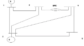
In order to investigate the feasibility of the proposed technique, a large number of power systems of different sizes and under different system conditions have been tested. It should be pointed out that the results are under so-called normal power flow, i.e. the control parameters of UPFC are given and UPFC is operated in an closed -loop form. All the results indicate good convergence and high accuracy achieved by the proposed method. In this section, the IEEE 5-bus system and a 14-bus practical system have been presented to numerically demonstrate its performance. It have been used to show quantitatively, how the UPFC performs. The original network is modified to include the UPFC. This compensates the line between any of the buses. The UPFC is used to regulate the active and reactive power flowing in the line at a pre specified value. The load flow solution for the modified network is obtained by the proposed power flow algorithm and the Matlab program is used to find the control setting of UPFC for the pre specified real and reactive power flow between any buses and the power flow between the lines are observed the effects of UPFC. The same procedure is repeated to observe the power flow between the buses. (Depending on the pre specified value of the active and reactive power the UPFC control setting is determined after the load flow is converged.).
Test results for IEEE 5 bus system
The performance of UPFC on the IEEE 5 bus system shown in figure4.
Fig 4 IEEE 5 bus system
Test results without UPFC
The voltage profile of the system is tabulated below:
The Power flow profile of the system
Bus code
Real power(p.u) (((p.u)
Reactive power(p.u)
Loss(p.u)
1-2 0.896246 0.868027 0.028772
1-3 0.420055 0.192529 0.016028
2-3 0.244368 -0.034026 0.003649
2-4 0.276769 -0.024054 0.004666
2-5 0.546338 0.053060 0.012304
3-4 0.194745 0.040617 0.000420
4-5 0.066428 0.009338 0.000462
Test results with UPFC (between bus 3 & 4)
The voltage profile of the system with pre-specified real and reactive power flows as 0.4 and 0.02. Bus
code
Voltage(p.u) Angle(rad) Angle(deg)
1 1.060000 0.000000 0.000000
2 0.992621 -0.033974 -1.946578
3 0.981487 - 0.080021 -4.584891
4 0.977982 -0.085585 -4.903633
Bus code Voltage(p.u) Angle(rad) Angle(deg)
1 1.060000 0.000000 0.000000
2 0.998054 -0.018069 -1.035270
3 0.990627 -0.047300 -2.710086
4 0.988389 -0.045750 -2.621289
5 0.972024 -0.075181 -4.307549
The choice of “ ” and “ ” are valid
The control settings of UPFC are:
Voltage( in p.u) Phase angle( in rad) Phase angle( in deg)
0.013630 -1.817928 -104.159581
The Power flow profile of the system Bus code
Real power (p.u)
Reactive power(p.u)
Loss(p.u)
1-2 0.615899 0.858253 0.020914
1-3 0.279573 0.190009 0.008952
2-3 0.157541 -0.028911 0.001500
2-4 0.153222 -0.015307 0.001415
2-5 0.484222 0.053322 0.009603
3-4 0.400464 0.019989 0.000951
4-5 0.126755 0.002453 0.001375
Test results with UPFC (between bus 2 &5)
The voltage profile of the system is:
The choice of “ ” and “ ” are valid
The control setting of UPFC is
Bus code Voltage(p.u) Angle(rad) Angle(deg)
1 1.060000 0.000000 0.000000
2 0.998937 -0.015406 -0.882724
3 0.988461 -0.059093 -3.385767
4 0.985640 -0.061540 -3.526007
5 0.978559 -0.044272 -2.536618
The Power flow profile of the system
Bus code
Real power (p.u)
Reactive power(p.u)
Loss(p.u)
1-2 0.568953 0.857510 0.019900
1-3 0.329123 0.185785 0.010969
2-3 0.234625 -0.034794 0.003323
2-4 0.250920 -0.023983 0.003787
2-5 0.400231 0.019998 0.007340
3-4 0.099455 0.050129 0.000138
4-5 -0.053549 0.023245 0.000422
VI. CONCLUSION
The unified power flow controller provides simultaneous or individual controls of basic system parameters like transmission voltage, impedance and phase angle, thereby controlling transmitted power.
In this thesis an IEEE 5-bus system is taken into consideration to observe the effects of UPFC. Load flow studies were conducted on given system to find the nodal voltages, and power flow between the nodes. The MATLAB program is run with and without incorporation of UPFC. The UPFC is incorporated between buses (3, 4) and (2,5) to improve the power flow between the lines to a pre-specified value. From the results it has been observed that the power flow between the lines is improved to a pre-specified value. Depending on the pre-specified value the UPFC control settings were determined. The real power losses between the lines were decreased after the incorporation of UPFC.
So, it can be concluded that after the incorporation of UPFC the voltage profile and power flow between the lines improves. Also by using this program, control setting of UPFC for different pre-specified power flows can be obtained.
REFERENCES
1. W. L.Feng, H. W. Nagan: “control settings of Unified power flow controllers through a robust load flow calculations”, IEEE proceedings on generation, transmission and distribution. Vol146. No. 4, July 1999.
2. Nabavi-Naiki. A and iravani. M. R: “steady state and dynamic models of Unified power flow controller for power system studies”, IEEE Transactions power systems, vol. 11, no. 4, nov 1996.
3. C. R. fuerte Esquivel, Acha. E: “unified power flow controller; a critical comparison of Newton-Raphson UPFC algorithms in power flow studies” IEEE proceedings on generation, transmission, distribution, Vol143, no.5, September 1997.
4. C.R Fuerte Esquivel, Acha.E:”Newton-Raphson algorithms for the reliable solutions of large power networks with embedded FACTS devices “.IEEE proceedings on generation, transmission, distribution, Vol143, no.5,September 1996.
5. Ch.Chengaiah, G.V. Marutheswar and R.V.S. Satyanarayana “Control Setting of Unified Power Flow Controller through Load flow calculations “ Vol.3 , No.6 , December 2008
6. N.G.Hingorani & Naren “Understanding FACTS”IEEE Press, 2000. 7. C.L.Wadhwa “Electrical power systems”.Third edition 2003.
8. W.Stagg & A.H.El-abiad “computer method in power system analysis” International student Edition (McGrawHill Inc., 1968). 9. Hadi saadat “Power system analysis” (Tata Mc Graw Hill Edition 2002).
Appendix 1
Data for IEEE 5-bus system
The data for the system under consideration is as follows:
Bus code Impedance( Line charging( )
1-2 0.02+j0.06 0.0+j0.030
1-3 0.08+j0.24 0.0+j0.025
2-3 0.06+j0.18 0.0+j0.020
2-4 0.06+j0.18 0.0+j0.020
2-5 0.04+j0.12 0.0+j0.015
3-4 0.01+j0.03 0.0+j0.010