Issue 1
MULTI-TONE GENERATOR
V-5335500
by
PagePac
®INTRODUCTION
The Multi-Tone Generator (MTG) is a compact, versatile multi-tone generator as well as a Night Bell for a Telephone System. Six different information tones plus Night Bell are provided, each of which are priority sensitive and individually selectable. The Multi-Tone Generator utilizes most paging equipment for all page/all call applications.
NOTE: If the host telephone system does not have a page port, then a Loop Start Trunk Adapter can be used from the MTG J2 connector to the Loop Start Trunk.
SPECIFICATIONS
FEATURES
• Night bell activation by a ringing voltage and/or AC or DC voltages • 6 information tones initiated by contact closures
• Compatible with most paging equipment • Tone level adjustment
• Quick installation with “piano keyboard” style terminal strip and modular jacks • Interfaces to mechanical or electronic time clocks for 7 sec. tone/alarm
• Comes with its own 12 VAC power supply that plugs into any 120 VAC, 60 Hz outlet • CSA/NRTL Certified
• Desk, Shelf or Wall mountable
Dimensions/Weight
• 5.5”W x 4.5”D x 2.0”D (13.4cm x 11.4cm x 5.1cm) • 2.0 lbs (0.9 kg)
Environment
• Temperature: -10 to 50°C (14 to 104°F)
• Humidity: 5 to 95%
Power Requirements
• Nominal 12VAC at 60 Hz. The AC power is provided by a 12 VAC wall plug type external transformer, supplied with the MTG.
• The AC input power may vary from 95V to 1130V at the wall plug.
OPERATION
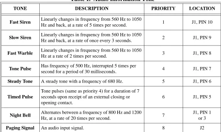
The Multi-Tone Generator produces five different tones by contact closure. The sixth tone (time clock input port) is activated by making, or breaking contacts (see Table 1). Requested tones are switched as indicated by the appropriate contact closure onto the paging audio path and provides a contact closure to turn on the connected paging equipment for the duration of the tone request.
Figure 1. Rear View of Multi-Tone Generator
Table 1. Audio Information Tone
TONE DESCRIPTION PRIORITY LOCATION
Fast Siren Linearly changes in frequency from 560 Hz to 1050
Hz and back, at a rate of 5 times per second. 1 J1, PIN 10
Slow Siren Linearly changes in frequency from 560 Hz to 1050
Hz and back, at a rate of once every 3 seconds. 2 J1, PIN 9
Fast Warble Linearly changes in frequency from 560 Hz to 1050
Hz at a rate of 2 times per second. 3 J1, PIN 8
Tone Pulse Has frequency of 500 Hz, interrupted 5 times per
second for a period of 30 milliseconds. 4 J1, PIN 7
Steady Tone A steady tone with a frequency of 680 Hz. 5 J1, PIN 6
Timed Pulse
Tone pulses (same as priority 4) for a duration of 7 seconds upon receipt of an external closing or opening contact.
6 J1, PIN 5
Night Bell Alternates between a frequency of 800 Hz and 1200
Hz, at a rate of 20 times per second. 7
J1, PIN 1 or 3
Paging Signal An audio input signal. 8 J2
J1
J2 J3
TONE
MIN MAX
POWER
PAGE INPUT OUTPUT
PAGE/TONE IN OUT J4 J5
FA
ST S
IREN
SL
OW SI
RE
N
FA
ST W
A
RB
LE
STEADY TO
NE
RI
NGER
COM. AC
/D
C
PU
LSE
D
T
O
NE
RETUR
N
NIGHTBELL
LEVEL
TIMED PULSE
1 3 4 5 6 7 8 9
Night Bell Functions
The MTG’s Night Bell function is activated through J1, Pins 1, 2 and 3 connector (Night Bell). If the activating signal is a nominal 70 Vac, 20 cycle ringer voltage use Pins 2 & 3. The night bell can also be activated by a key system generating 10 to 30 volts AC at 60 cycles or it can be driven by 24 to 48 Vdc, disregarding polarity on Pins 1 & 2.
The customer owned phone system audio and control lines are attached to J2 (Page Input) and are passed unchanged through the MTG to J3 (Page/Tone Output) when it is in the inactive, (Tones/Night Bell Off) state. This mode is referred to as “Page Through”. The MTG, when accessed, will disconnect J2 from J3 and connect the MTG’s audio and control lines to J3.
Table 2. Connectors and Pin Identification
Connector J1. 10 Pin “Self-Securing” connector. Pin 10 Fast Siren
Pin 9 Slow Siren
Pin 8 Fast Warble
Pin 7 Tone Pulse
Pin 6 Steady Tone
Pin 5 Timed Pulse
Pin 4 Night Bell
Pin 3 Paging Signal
Pin 2 Common for Night Bell
Pin 1 AC/DC input for Night Bell trigger
Connectors J2, J3, J4 and J5. Quad RJ11 type connectors. J2: Page Input Interface
Pin 6 Connected to J3-Pin 6
Pin 5 Control In
Pin 4 Page Audio In
Pin 3 Page Audio In
Pin 2 Control 1 In
Pin 1 Connected to J3-Pin 1
J3: Page Amplifier Output Interface Pin 6 Connected to J2-Pin 6
Pin 5 Control 1 Out
Pin 4 Page/Tone Out
Pin 3 Page/Tone Out
Pin 2 Control Out
Table 2. Connectors and Pin Identification (Continued)
Time Clock Functions
The MTG’s Time Clock (Timed Pulse) function is activated by momentary make and/or break contact (i.e., transition from N.O. to N.C. and N.C. to N.O.).
The Time Clock (Timed Pulse) function can be activated from a mechanical or electronic time clock and will respond to both the on and off time trip points. A single transition will produce a seven second beep tone.
NOTE: An interval greater than 15 seconds is required between activations to allow for proper reset of the clock activated tone circuit.
INSTALLATION
Installation of the MTG differs depending on how the MTG will be used. There are two different proce-dures for installing the MTG with night bell service; when the host telephone system supplies an AC ringing generator or when the host telephone system supplies 24/48 volts DC. In addition, installation procedures are included for interfacing the MTG to PagePac® paging products.
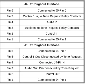
J4. Throughout Interface. Pin 6 Connected to J5-Pin 6
Pin 5 Control 1 In, to Tone Request Relay Contacts
Pin 4 Audio In
Pin 3 Audio In, to Tone Request Relay Contacts
Pin 2 Control In
Pin 1 Connected to J5-Pin 1
J5: Throughout Interface. Pin 6 Connected to J4-Pin 6
Pin 5 Control 1 Out, Disconnected by Tone Request
Pin 4 Connected J4-Pin 4
Pin 3 Audio Out, Disconnected by Tone Request
Pin 2 Control Out
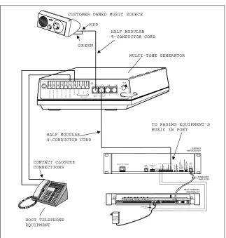
Alert Tone or Night Bell Service -- Host Telephone System Supplies a Contact
Closure (Figure 2)
• Connect one lead (either lead) of the contact closure from the host phone system to the Return Terminal (4) at connector J1 on the back panel of the MTG.
• Connect the other lead of the contact closure to one of the desired tone terminals (6-10) at connector J1 on the MTG’s rear panel or to the Timed Pulse Night Terminal (5). Refer to Table 1 for a list of infor-mation tones and their priorities.
• The output of the MTG is provided at connector J3, which is a modular jack. Use the red/green pair of wires of a half-modular cord to connect from J3 to the Music-In port of the paging equipment.
If the customer is already providing background music, it must be disconnected from the paging equipment and run through the MTG. Make these connections through another half-modular cord connected to the J2 jack. Background Music (BGM) can then be provided from J3 to the Music-In port of the paging equipment.
• Plug the AC power cord (with attached power supply), into a nearby 110 Volt Ac, 60 Hz outlet. The LED on the MTG rear panel will light.
Figure 2. Night Bell Contact Closure Activation
MULTI-TONE GENERATOR CUSTOMER OWNED MUSIC SOURCE
R ED
G R EEN
J1
J2 J3
1 3 4 5 6 7 8 9
10 2
TO NE
M IN M A X
PO W ER
P A G E I N PUTO U TP U T
PA G E/TO N E IN O U T
F
AST
SI
RE
N
SL
O
W
SI
RE
N
FA
S
T
WA
R
B
LE
ST
EAD
Y
TO
N
E
RI
NGE
R
CO
M
.
AC
/DC
PU
L
S
ED
TO
N
E
RE
TU
R
N
N IG H TBELL
LEVEL
TI
ME
D
PU
L
S
E
J4 J5
HOST TELEPHONE EQUIPMENT
CONTACT CLOSURE CONNECTIONS
HALF MODULAR 4-CONDUCTOR CORD
HALF MODULAR 4-CONDUCTOR CORD
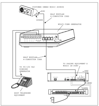
Night Bell Service -- Host Telephone
System Provides 90 to 105 Volt AC Ringing Generator (Figure 3)
• Connect the Night Bell source of the Ringing Generator from the host phone system to the MTG at connector J1 across terminals 2 and 3.
• The output of the MTG is provided at connector J3, which is a modular jack. Use the red/green pair of wires of a half-modular cord to connect from J3 to the Music-In port of the paging equipment. If the customer is already providing background music, then it must be disconnected from the paging equip-ment and run through the MTG. Make these connections through another half-modular cord con-nected to the J2 jack. Background Music (BGM) can then be provided from J3 to the Music-In port of the paging equipment.
• Plug the AC power cord (with attached power supply), into a nearby 110 volt AC, 60 Hz outlet. The LED on the MTG’s rear panel will light.
Figure 3. Night Bell Ring Voltage Activation
MULTI-TONE GENERATOR CUSTOMER OWNED MUSIC SOURCE
R ED
G R EEN
J1
J2J3
1 3 4 5 6 7 8 9
10 2
TO NE
M IN M A X
PO W ER
P A G E IN PUTO U TP U T
PA G E/TO N E IN O U T
FA
S
T SI
RE
N
SL
O
W
SI
RE
N
FA
S
T WA
R
BL
E
ST
EAD
Y
TO
N
E
RI
NGE
R
CO
M
.
AC
/DC
PU
L
SED
TO
N
E
RE
T
U
R
N
N IG H TBELL
LEVEL
TI
ME
D
PU
L
S
E
J4 J5
HOST TELEPHONE EQUIPMENT
TO 90/105 VAC RINGING GENERATOR
HALF MODULAR 4-CONDUCTOR CORD
HALF MODULAR 4-CONDUCTOR CORD
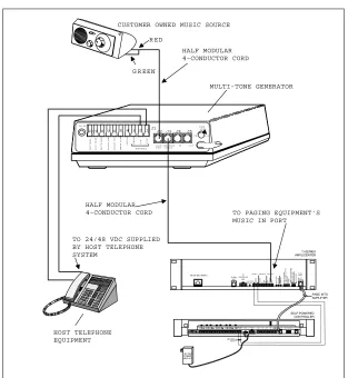
Night Bell Service -- Host Telephone
System Supplies 24/48 Volts DC (Figure 4)
• Connect the Night Bell source of DC voltage from the phone system to the MTG at connector J1. The DC voltage must be connected across terminals 1 and 2.
• The output of the MTG is provided at connector J3, which is a modular jack. Use the red/green pair of wires of a half-modular cord to connect from J3 to the Music-In port of the paging equipment. If the customer is already providing background music, then it must be disconnected from the paging equip-ment and run through the MTG. Make these connections through another half-modular cord con-nected to the J2 jack. Background Music (BGM) can then be provided from J3 to the Music-In port of the paging equipment.
• Plug the AC power cord (with attached power supply), into a nearby 110 volt AC, 60 Hz outlet. The LED on the MTG’s rear panel will light.
NOTE: These methods of connection will allow the MTG to share the Music-In port with the customer’s music source.
NOTE: With power removed, the “Page Through” mode will be functional with all tone functions dis-abled. Adjust the MTG’s output level with the volume contol located on the unit’s rear panel
(see Figure 1). Output level is from full off (min.) to a level suitable for driving up to four, 600 Ohm paging amplifier input loads (max.).
Figure 4. Night Bell Service - 24/48 Volts DC Activation
MULTI-TONE GENERATOR CUSTOMER OWNED MUSIC SOURCE
R ED
G R EEN
J1 J2J3 1 3 4 5 6 7 8 9 10 2
TO N E
M IN M A X
PO W ER
P A G E IN PU TO U TP U T
PA G E/TO N E IN O U T
FAST SI RE N SL O W SI RE N FA S T WA R BL E ST EAD Y TO N E RI NGE R CO M . AC /DC PU L S ED TO N E RE T U R N
N IG H TBELL
LEVEL TI ME D PU L S E
J4 J5
HOST TELEPHONE EQUIPMENT
TO 24/48 VDC SUPPLIED BY HOST TELEPHONE SYSTEM
HALF MODULAR 4-CONDUCTOR CORD
HALF MODULAR
4-CONDUCTOR CORD TO PAGING EQUIPMENT'S
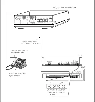
Emergency Alerts, Break Time/Quitting Time Tones -- (Figure 5)
NOTE: The phone system, alarm system, or time clock must be able to provide a contact closure or closures, depending on how many tones are required.
NOTE: This method of connection coupled with the addition of PagePac® Plus Controller, will give the MTG control over any paging operations. This means that voice pages will be overriden if an alerting tone or break/quitting time tone is enabled.
NOTE: With power removed, the “Page Through” mode will be functional with all tone functions disabled. Adjust the MTG’s output level with the volume contol located on the unit’s rear panel
(see figure 1). Output level is from full off (min.) to a level suitable for driving up to four, 600 Ohm paging amplifier input loads (max.).
• Connect one lead (either lead) of the contact closure from the host phone system to the return terminal at J1 on the back panel of the MTG.
• Connect the other lead of the contact closure to the appropriate tone terminal at J1 on the MTG’s rear panel. Closures (control pairs) from alarm systems should use higher priority. The “Fast Siren” tone is the highest priority and the “Beep” (7 second) tone is the lowest.
• The output of the MTG is found at J3, which is a modular jack on the MTG’s rear panel. Use a half-modular cord to connect from J3 to the Attendant Input port of the PagePac using the red/green pair. The black/yellow pair from the MTG is then connected to the Attendant Access Control pair of the PagePac Plus Controller.
• Plug the AC power supply into a 110 volt AC, 60 Hz outlet. The LED on the MTG’s rear panel will light.
MULTI-TONE GENERATOR
J1
J2 J3
1 3 4 5 6 7 8 9
10 2
TO N E
M IN M AX
PO W ER
PAG E IN PU TO U TPU T
PAG E/TO N E IN O U T
F
AST
SI
RE
N
SL
O
W
SI
RE
N
FA
ST
WA
R
B
L
E
ST
EA
D
Y
TO
N
E
RI
NG
ER
CO
M
.
AC
/DC
PU
LS
ED
TO
NE
RE
T
U
RN
N IG H TB E LL
LE V E L
TI
ME
D
PU
L
S
E
J4 J5
CONTACT CLOSURE CONNECTIONS
HOST TELEPHONE EQUIPMENT
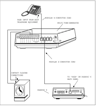
Emergency Alerts, Break TIme/Quitting Time Tones -- PagePac® 6 (Figure 6)
NOTE: The phone system, alarm system, or time clock must be able to provide a contact closure or clo-sures: depending on how many tones are required.
NOTE: This method of connection will give the MTG control over any paging operation. This means that voice pages will be overriden if an alerting tone or break/quitting time tone is enabled.
NOTE: With power removed, the “Page Through” mode will be functional with all tone functions dis-abled. Adjust the MTG’s output level with the volume contol located on the unit’s rear panel
(see Figure 1). Output level is from full off (min.) to a level suitable for driving up to four, 600 Ohm paging amplifier input loads (max.).
• Connect one lead (either lead) of the contact closure from the host phone system to the return terminal at J1 on the rear panel of the MTG.
• Connect the other lead of the contact closure to the appropriate tone terminal at J1 on the MTG’s rear panel. Closures (control pairs) from alarm systems should use higher priority. The “Fast Siren” tone is the highest priority and the “Beep” tone is the lowest.
• The output of the MTG is found at J3, which is a modular jack on the MTG’s rear panel. Use a full-modular, 4-conductor cord to connect from J3 to the MTG to “PAGE” on the PagePac® 6 back panel. • Plug the AC power cord (with attached power supply), into a nearby 110 volt AC, 60 Hz outlet. The
LED on the MTG’s rear panel will light.
Figure 6. PagePac 6 Activation
MULTI-TONE GENERATOR J1 J2 J3 1 3 4 5 6 7 8 9
10 2 TO NE
M IN M AX PO W ER
PAG E INPUTPAG E/TO NE IN O UTO UTPUT
FA S T SI RE N SL O W SI RE N FA S T WA R B L E ST EA D Y TO N E RI NG E R CO M . AC /DC PU L S ED TO N E RE T U RN NIG HTBELL LEVEL TI ME D PU L S
E J4 J5
PAGEPAC 6
TO "PAGE" ON PAGEPAC 6 BACK PANEL
12 12 3 4 5 6 7 8 9 1011 CONTACT CLOSURE CONNECTIONS
MODULAR 4-CONDUCTOR CORD
MODULAR 4-CONDUCTOR CORD PAGE INPUT FROM HOST
TELEPHONE EQUIPMENT
P A G E V O L
S P K R S M U S I C I N
M U S I CV O L P A G E P O W E RO U T
TECHNICAL ASSISTANCE
When calling, have a VOM and a telephone test set available and call from the job site. Call (540) 427-3900 and ask for PagePac Technical Support, or call (540) 427-6000 for Valcom 24-hour Automated Support or visit our websites at http://www.pagepac.com and www.valcom.com.
Should repairs be necessary, attach a tag to the unit clearly stating company name, address, phone number, contact person, and the nature of the problem. Send the unit to:
Valcom, Inc. PagePac® Repair Dept.
5614 Hollins Road Roanoke, VA 24019-5056
Table 3.
Troubleshooting
TROUBLE POSSIBLE CAUSES POSSIBLE SOLUTIONS
Power “ON”
a) Transformer not plugged
into a working AC outlet. Move transformer to a different outlet.
LED Not Illuminated b) Transformer Defective Replace transformer.
c) MTG defective. Replace MTG.
a) Tone volume control not adjusted.
Adjust control to higher volume.
Low Tone Output Volume
b) Tone output feeding more than (4) 600 Ohm inputs.
Reconfigure installation.
c) Tone output not feeding into
600 Ohm inputs. Obtain matching device for 600 Ohms.
a) Tone volume control off. Adjust control to higher volume.
No Tone Output (Green LED Illuminated)
b) Closure/control leads not operating.
Check control leads with meter to isolate.
c) Mis-wire between host system and MTG. Listen for MTG relay operation. d) Ringer voltage or DC voltage for Night Bell
SECONDARY CIRCUIT PROTECTION
IMPORTANT INFORMATION
This equipment is for use on telephone wiring containing a secondary circuit protector. This paging equipment requires a secondary circuit protector where applicable (see Figure 7).
The secondary circuit protector must be located between the primary protector and the paging equip-ment. Refer to the Safety Information below.
Example Configuration Requiring Secondary Protection
When Paging Equipment is Connected Directly to the Telephone Network
SAFETY INFORMATION
• The secondary circuit protector is used when connecting paging equipment directly to telephone lines that may be exposed to high voltage power lines.
• Never install telephone wiring during a lightning storm.
• Never install telephone jacks in wet locations unless the jack is specifically designed for wet locations. • Never touch uninsulated telephone wires or terminals unless the telephone line has been
disconnected at the network interface.