ISSN 2348 – 7968
Simulation of tube hydroforming process using bidimensional
finite element analysis with HyperWorks
Juan Carlos Cisneros1, Isaías Angel2
1
Engineering Department, UPAEP/ Electronic Faculty, Puebla, Puebla, 72410, Mexico
2
AgDesign, Inc., 2491 Simpson St. Kingsburg, CA 93631, USA
Abstract
Nowadays, an intense competition exists among the manufacturing enterprises that try to bring to the market products with a better quality, the least cost and as fast as possible. Because of this, particularly the automotive ones are looking for alternatives that will improve their production processes. The hydroforming process for tubular parts had benefited manufacturing industries, especially the automotive industry. This because by this process it is possible to obtain complex geometry pieces, lighter, more resistant, made with fewer steps and at the lowest price, which would have been harder with other methods. In this work, the simulation of tubes’ hydroforming process is presented into a virtual environment of Finite Element Analysis, this to obtain the appropriate hydroforming parameters for the Elbow Pipe piece that takes part of the exhaust system of an automobile and which model was obtained by the reverse engineering method, using a 3D CREAFORM scanner to scan. The material used for the process simulation was Mild Steel DC05.
Keywords: Hydroforming, automotive industry, Finite Element, 3D scanning.
1. Introduction
The environmental deterioration and the scarcity of natural resources have led the enterprises to seek more ecological alternatives for producing the goods that humanity needs. The hydroforming process is a good alternative for obtaining products at the lowest cost, lighter (which decreases the material consumption) and with a superior quality than the ones obtained by traditional techniques like stamping and parts soldering [1].
The hydroforming process consists of deforming plastically a metal sheet (sheet hydroforming) or a metallic tubular component (tube hydroforming), by
the action of a pressurized fluid, that usually is water mixed with anticorrosive additives. In this process many tools are required, like: a vise to hold raw material, a pressure supply system, pistons for the supply of axial feeding (in case of tube hydroforming) and a process control system.
The industry with more benefits by the hydroforming and specially by the tube hydroforming is the
automotive one, that has implemented this technique in their products for reducing the parts fabrication steps, obtaining a greater component’s resistance, minimizing the cost of tools, achieving more tight tolerances compared to the stamping process and above all lower manufacturing costs [2].
The tube hydroforming processes in which the required pressure for the conformation of the component is lower than 12 000 Psi, are known as low-pressure hydroforming, while the ones that exceed that pressure are known as high-pressure hydroforming. A combination of both types is known as mixed hydroforming [1].
The hydroforming process’s success is due to the appropriate combination of load curves (internal pressure - tube’s axial feeding), the piece’s material properties and the process conditions [3].
A methodology that has served as support for designing engineers in the solution of many complex problems and in our particular case, the obtaining of appropriate parameters for hydroforming, is the Finite Element Analysis.
__________________
1Juan Carlos Cisneros is a Professor and researcher at the Universidad Popular Autónoma del Estado de Puebla (UPAEP). [email protected]
2
ISSN 2348 – 7968 This methodology consists in dividing a complex
geometry into little elements, solving each element’s balance equations and after that, assembling the results in order to obtain the total solution to the problem [4, 10]. Thanks to the information technologies advance, many Finite Element Analysis softwares have been developed and with this the obtaining of appropriate parameters with the lowest possible error index for the pieces production has been streamlined.
This work focuses on the tube hydroforming process (TH), it aims to determine the appropriate hydroforming parameters for the fabrication of the piece known as Elbow Pipe, using the material Mild Steel DC05, in a virtual environment, by use of the Finite Element Analysis software named HyperWorks, in order to reduce process’s costs and scrap.
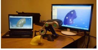
Figure 1 Equipment used for the obtaining of the Elbow Pipe model.
The paper is organized as follows: In Section 2 the Methodology is presented which is divided in two stages: (1) the application of the inverse engineering technique using a 3D scanner, in order to obtain the piece’s model and to build the simulation’s tool; (2) the hydroforming process’s simulation in the incremental module of HyperWorks
Section 3 presents the main Results of the study. The final parameters of the Elbow Pipe hydroforming, the FLD diagram and the Distribution of Von Mises stress.
Finally Section 4 contains the Conclusions of this research. In general, the focus in the Mild Steel DC05 that offers a good conformability for the Elbow Pipe and how the parameters have and influence in the behavior of the Hydroforming process.
2.0 Methodology
The simulation process of this component was divided in two stages. The first stage consisted in the application of the inverse engineering technique using a 3D scanner in order to obtaining the piece’s model and building the simulation’s tooling. The second stage consisted in the hydroforming process’s simulation in the incremental module of HyperWorks.
2.1 Application of the inverse engineering technique by using 3D scanning and the construction of tooling
Inverse engineering refers to the process of recreating the form or the CAD mathematic model of a component by a series of measurements of it. Inverse engineering has been used widely in the aerospace industry, in the transportation industry and auxiliary industries, medicine industry, and especially in the automotive industry [5, 13]. Inverse engineering technique is based on a sensor for collecting the measurements of the part and a specific software that transforms the data into a CAD model. Generally 3D sensors are used and they’re classified into contact sensors and no-contact sensors. In the contact sensors class we find the coordinate measuring machines and among the no-contact sensors we find systems that use the laser or light technologies in order to work.
Before the hydroforming simulation with HyperWorks it was necessary a 3D scanning for obtaining the Elbow Pipe’s model and making the tooling and for that a HANDYSCAN 3D SCANNER by CREAFORM was used, which system is based on the usage of a laser and two cameras, that through triangulation determines the surface points’ position, for producing a point cloud that defines the model (Figure 2) [8].
Figure 2 HANDYSCAN 3D Scanner by CREAFORM.
The process for obtaining the tooling is summarized as follows:
1.- The first step was the obtaining of Elbow Pipe’s model, by the 3D scanning of the original piece with the Handyscan 3D Scanner by CREAFORM. The figure 1 shows the Elbow Pipe component and the equipment used for the model obtaining.
ISSN 2348 – 7968
Figure 3 Process for obtaining the model of the Elbow Pipe with the CAD software GEOMAGIC DESIGN and SolidWorks: a) cloud of points
from the scanning process, b) cloud of points improved with GEOMAGIC DESIGN and c) CAD model obtained with SolidWorks.
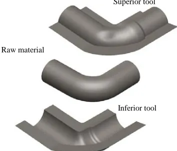
3.- Later based on the refined model of the piece obtained from the scanning, the tooling that would be used in HyperWorks was built with the CAD software, SolidWorks. The figure 4 shows the aforementioned tooling.
Figure 4 Tooling and raw material built in SolidWorks.
Own elaboration.
2.2 Simulation with HyperWorks
The obtained tooling from SolidWorks is exported to HyperWorks in an .igs format for the hydroforming process’s simulation. The meshing of the pieces is made using the tools from R-Mesh for the tooling and AutoMesh for the raw material. The used element was bidimensional. La figure 5 shows the mesh of the aforementioned components.
Figure 5 Mesh of the tooling and raw material of the Elbow Pipe: a) Mesh of the tooling, minimum length of the element 0.25 mm and
maximum length of the element 10 mm, b) Mesh of 4 mm. Own
elaboration.
Table 1.- Mechanical properties of Mild Steel DC05 [6].
Mechanical properties of Mild Steel DC05 and raw material’s measurements.
Property Angle according to the Rolling direction
0º 45º 90º
E(Young’s Module) 191 000
Mpa
v (Poisson’s Coefficient ) 0.34
TS (Tensile Strength) 294.4 Mpa
Eo (Pre-Strain) 0.0064
r (Lankford Coefficient) 1.888 1.464 2.193
rm(Normal Anisotropy) 1.752
n (Strain hardening Coefficient)
0.254
K (Hardening coeficient) 538.5 Mpa
YS (Yield Stress) 149 Mpa
Tube’s nominal diameter 60 mm
Wall’s thickness 3 mm
Length 487 mm
The designate material for the raw material is Mild Steel DC05 which mechanical properties and tube’s measurements are shown in the Table 1. The tube’s measures we’re chosen taking in consideration the commercially available ones.
The hydroforming simulations were made in the incremental module of HyperWorks, the general diagram of those simulations is shown in the figure 6.
To expedite the obtaining of hydroforming parameters two mesh sizes were used. Initially a 7 mm mesh was used for obtaining the first appropriate values of the piece and for the obtaining of the definitive parameters a 4 mm mesh was used, in order to reduce the error and obtain a better approximation to the optimum parameters.
Superior tool
Inferior tool Raw material
a) b) c)
a)
ISSN 2348 – 7968
Figure 6 General diagram of the simulations in HyperWorks.
Self-Feeding was also used to minimize the number of iterations for finding the appropriate parameters for the hydroforming of the piece [7, 11, 12].
3. Results
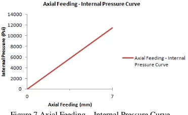
After much iteration the final parameters, shown in Table 2, were obtained. The figure 7 shows the axial feeding - internal pressure curve.
Table 2 Final parameters of the Elbow Pipe hydroforming.
Parameter Value
Pi (Initial Pressure) 0 PSI
Pf (Final Pressure) 11 500 PSI (79.29 Mpa)
V (Speed) 2000 mm/s Friction (Coulum) 0.05 Axial Feeding A 0 mm Axial Feeding B 7 mm
Figure 7 Axial Feeding – Internal Pressure Curve.
In the figure 8 we can determine that most of the points are in the safe zone and out of the marginal area of 3% based on the FLC. It is possible to improve the marginal area to the 10% by increasing the axial feeding for making all the points move to the safe zone determined by that limit, nevertheless, by doing this the compression in some zones of the piece tends to increase and there’s a risk of having wrinkles in the final component. It also can be distinguished that the deformations are found in the regions of deep drawing, uniaxial tensile and in a minor proportion in the simple tension region [12, 14].
Figure 8 FLD of the definitive parameters with the 4 mm mesh.
As can be seen in the number 1 marked zone in the figure 8, most of the points that suffered maximum compression belong to the B end, not taking part of the final piece. In the number 2 marked zone it is shown a certain degree of, due that the mold or tooling has a protuberance that forms a cavity in the piece. Nevertheless the compression is minimal and does not affect the piece’s form.
Importation of the IGES pieces into HyperWorks.
Debugging and positioning of the pieces. (Autocleanup and
translate).
Material allocation and raw material section.
Meshing of the pieces.
ISSN 2348 – 7968
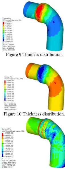
Figure 9 Thinness distribution.
Figure 10 Thickness distribution.
Figure 11 Distribution of Von Mises stress.
Regarding to the thinness distribution, the thickness and the Von Mises stress. We can see in the figure 9 that the maximum thinness is of 22.79 % that corresponds to the red area and the minimum thinness is of -6.586%, the negative sign represents the compression of the zones as consequence of the axial feeding. Referring to the tube’s wall thickness distribution (figure 10), the maximum thickness is of 3.198 mm, and corresponds to the lower identified deformation zones, identified with intense orange color, while the minimum thickness is of 2.316 mm identified with the intense blue color, and corresponds to the greater deformation zones. At last, in the figure 11 we can see that the maximum Von Mises stress is of 413.6 Mpa, and that it is greater than the yield stress (149 Mpa), which indicates that the material suffered a plastic deformation
.
4. Conclusions
We can conclude that the Mild Steel DC05 offers a good conformability for the Elbow Pipe piece and that the hardening deformation exponent (n=0.254) was a determinant for avoiding fractures in the piece. The offset of 3% of the marginal area offers an unlimited
increased, nevertheless, it would mean an increase in the piece’s compression and the wrinkle tendency. The magnitude of the friction coefficient (0.05) was a determinant for relatively lowering the material’s compression. Because of the pressure (11 500 psi < 12 000 psi) required for this piece’s hydroforming, we can classify it as a low-pressure hydroforming. At last due that the tooling was obtained with the inverse engineering technique (3D scanning) it is recommended to edit the obtained surfaces for eliminating the irregularities and to avoid the obtaining of an inappropriate mesh that impedes the development of the simulation in HyperWorks.
References
[1] Harjinder, S. (2003). Fundamentals of Hydroforming. United States of America: SME.
[2] Nisahan, J. (2003). Modeling and Analisis of Dual Hydroforming Process. Thesis of Master in Sience Texas A&M University.
[3] Ibarrondo, I. (1985). Embutición Extraprofunda. Pais Vasco: Universidad del País Vasco.
[4] Zeid, I. (2005). Mastering CAD/CAM. New York. McGraw-Hill.
[5] Hoschek, J. (1996). Reverse Engineering. Stuttgart: Teubner. [6] Slota, J. and Jurčišin, M. (2012). Experimental and numerical analysis of the deep drawing process using optical measuring system. Technical University of Košice, Slovakia. [7] Aue-U-Lan, Y., Ngaile, Y. y Altan, A. (2004). Optimization of tube hydroforming uding process simulation and experimental verification. Journals of Materials Processing Technology. [8] www.creaform3d.com
[9] www.geomagic.com
[10] B. Yang, W. G. Zhang, S. H. Li. (2006). Analysis and finite element simulation of the tube bulge hydroforming process. The International Journal of Advanced Manufacturing Technology. [11] Koc, M. and Cora, O. N. (2008). Introduction and state of the art of hydroforming. Hydroforming for Advanced Manufacturing. CRC Pres Taylor & Francis Group.
[12] Green, D. E. (2008). Formability analysis for tubular hydroformed parts. Hydroforming for Advanced Manufacturing. CRC Pres Taylor & Francis Group.
[13] Xiao-Lei Cui, Xiao-Song Wang∗, Shi-Jian Yuan. (2014). Deformation analysis of double-sided tube hydroforming insquare-section die. Journal of Materials Processing Technology.
[14] Vinesh Raja. Kiran J. Fernandes. (2008). Reverse Engineering an Industrial Perspective. Springer Series in Advanced Manufacturing.
ISSN 2348 – 7968
simulation. In these areas he has published a book, a book chapter and numerous communications in national and international journals of high impact and has participated in various national and international conferences.