Available online: http://edupediapublications.org/journals/index.php/IJR/ Page 20
Novel VLSI Architecture of Fir with Lut Less Method
Using Distributive Arithmetic for DSP Applications
C SAIKUMAR RAJU (Research Scholar) 1, S. Heenakousar M.tech (assistant professor) 2
Golden Valley Integrated Campus, Angallu, Madanapalli
ABSTRACT
Adder and multipliers are used in many processors to accomplish fast arithmetic function. Many different adder architecture designs have been developed to increase the efficiency of the adder. A filter is used to pass a specific band of frequency. Depending on the response of the system, digital filters can be classified into Finite Impulse Response (FIR) and Infinite Impulse Response (IIR). Digital filters are widely used in many digital signal processing applications. Therefore digital filtering is one of the basic need of digital signal processing. In traditional fir filter consumes more power and area because of multipliers usage to avoid this disadvantage in this paper designs a new approach to design a fir filter by using distributive arithmetic method in lutless method. In this paper fir with traditional adder is existed design and fir filter using parallel prefix adder is the proposed design. Parallel prefix adders are the good adder for fast execution it is reduce the complexity of the multiplication process, it causes to reduce the power and area of the design Performance of all adder designs. And this project implemented for 64 bit lut less fir structure; these structures are synthesized on Xilinx 12.3 ISE tool. Key words: Registers, multiplexers, carry skip adder, Brent Kung adder, and accumulator and DA method.
I. INTRODUCTION
Area of Digital Signal Processing (DSP) is of extreme importance as it performs the processing of digital signal. A complex DSP system involves several adders and multipliers. An efficient design of adders and multipliers improves the performance of complex signal processing system.
Fundamental components are adders which are very frequently found in the many different networks that are in different blocks of many systems like controllers and processing chips. A system’s performance is basically estimated by the ability of the working of adder and multiplier Filter is a frequency selective network.
A filter allows a particular band of frequencies and attenuates all the remaining frequencies. Analog and digital are the two types of filter. Depending on the impulse response of a filter it is classified into two types one is finite impulse response and the other is infinite impulse response. In the industry of electronics digital filters are used. Compared to analog filters digital filters have attain much signal to noise ratio for this reason we use digital filters than analog filters.
Available online: http://edupediapublications.org/journals/index.php/IJR/ Page 21
engineers use digital filters to achieve better performance level that are difficult to obtain with analog filters. The three operations will do in digital filters are Addition operation or subtraction, Multiplication of a signal by a constant value and Delaying a digital signal by one or more sample periods.
A graphical means of describing a digital filter whereby the behavior of the filter is described by in below figure
Fig.1: Block Diagram of a Simple Digital Filter
𝛿 (𝑛)Is the unit impulse function given as input to a filter and its response is h (n). if the impulse response of a system is known, it is possible to calculate the system response for any input sequence x (n). at sample index n = 0 the unit impulse is applied to the system.
The impulse is non-zero only for values of n greater than or equal to zero i.e., h (n) is zero for n<0. This impulse response is said to be casual otherwise the system would be producing a response before an input has been applied. It is known from the time-invariance property of a Linear Time Invariant System that the response of a system to a delayed unit
impulse (𝑛 − 𝑘) . Tap delay fir filter equation (1)
𝑦[𝑛] = ∑ h(n) x(n − k) ( 1) N
𝑘=0
II. DISTRIBUTED ARITHMETIC METHOD-OVERVIEW
Multipliers are the complex and time consuming process in the FIR filter. In order to remove the redundancy of multiplication process, several multipliers-less method have evaluated. This multiplier less method is classified into two types namely methods based on conversion and methods based on memory.
In conversion based method, the coefficients of the FIR filter are converted into other numerical forms other than the binary forms for effective hardware implementation and reduced delay. Canonical Signed Digit is the numerical form, in which the coefficients are written in terms of powers of two is used to reduce the complexity of the multiplication process.
On the other hand Look up Tables is used for storing the pre calculated co products in memory based techniques. DA (Distributed Arithmetic) based on memory based techniques is trending architecture in recent years because of its high performance.
Available online: http://edupediapublications.org/journals/index.php/IJR/ Page 22
Where the fixed coefficients are represented as AK, the input signal is represented as xk and K is the number of input words. Xk can be modeled as
Where xk={bk0………..b k(N-1)}, the output equations can be expressed as
The equation (4) is the finalized form of Distributed Arithmetic Technique. The value of is either 0 or 1 and has 2k possible values. The pre-computed results are store in the ROM. The Size of the ROM is 2 x 2k, since it has to store both positive and negative values of bkn .hence
the size of the memory increases with the word size.
The Diagrammatic representation of the Binary based Distributed Arithmetic is shown in the figure 1.X1, X2, X3, X4 are the input lines which are carried as single bit with Least Significant Bit of b
kN-1and the sign bit of bk0as the Most
Significant bit. S is the sign bit timing signal. If S is set at position1 then S is set as 1 for sign bits and set as 0 for others. During the Clock cycle, the switch will be in position 2.
Figure2: Binary Based DA Technique
III.DISTRIBUTED ARITHMETIC ARCHITECTURE WITH LUTLESS
FIR FILTERS:
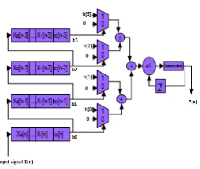
In LUT less DA method, the LUT is replaced with multiplexers and adders as shown in fig 6. Because of the absence of LUT, the structure is called LUT less architecture [8]. This results in reducing area and power consumption. The hardware requirement is less compared to the DA technique. For a 3rd order FIR filter, four multiplexers are used. Each multiplexer has two inputs.
One input is the coefficient of FIR filter and the other input is binary value 0. The LSB of input shift register is used as a select line for the multiplexer. If the select line is ‘1’, then the coefficient of the filter is passed to output. If the select line is ‘0’, then the binary value 0 is passed to the output.
Available online: http://edupediapublications.org/journals/index.php/IJR/ Page 23
Figure 3: LUT-less DA architectures
IV. BRENT-KUNG ADDER
Brent Kung adder is one of the parallel prefix adders. It is the most popular adder that is used to increase the speed of operation. These adders are designed by using carry look ahead adders structure. It consists of three stages Pre-processing carry propagation (p) and carry generation (g) signals. Calculation of the sum value by using carry generation and propagation signals. In the preprocessing stage carry propagate and generate equations are found by using the generalized equation Pi = Ai XOR Bi and Gi
= Ai AND Bi
By using these equations we proceed for further process i.e., calculating the carry values.
❖ The carry value c0 is generated by using p0 and g0 values.
❖ The carry value c1 is generated by using p1 and g1 and also the previous values p0 and g0.
❖ Similarly carry value c2 is generated using p2, g2 and previous values p1 and g1.
❖ The end value will be the final value of carry which is denoted here as Cout.
The generalized carry generate and carry propagate equations are
Cp = Pi Pi-1andCg = Gi + (Pi Gi-1)
Fig 4: carry generation and propagation network
The next stage is post processing stage in which final value of sum is calculated. The generalized equations are Si= Pi. Ci and Ci+1= (Pi .Ci) + Gi
Fig5: 4-bit Brent Kung adder
Available online: http://edupediapublications.org/journals/index.php/IJR/ Page 24
V. RESULTS
Figure 7: RTL Schematic
Figure 8: view technology schematic
Figure9: simulated waveform
Parameter FIR with CSKA
FIR with BKA
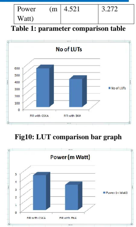
No of LUTs 554 401
Power (m Watt)
4.521 3.272
Table 1: parameter comparison table
Fig10: LUT comparison bar graph
Fig 11: power comparison bar graph
VI. CONCLUSION
In the last two decades, much architecture has been introduced for the design of low complexity fir operation. But there is no such improvement in the FIR design. This project gives the solution for that type of requirements. In traditional filter design methodologies consumes much power due to multiplier.
Available online: http://edupediapublications.org/journals/index.php/IJR/ Page 25
So from this project it has a chance to use the corresponding structure based on the industrial requirements. In future there may be a chance to develop the layouts for the structures.
REFERENCES
1) Kyung-Saeng K, Lee K (2003). Low-power and area efficient FIR filter implementation suitable for multiple tape, Very Large Scale Integration (VLSI) Systems, vol 11, No 1.2. S.F. Hsiao, JH ZhangJia, M-C Chen “ Low cost FIR filter designs based on faithfully Rounded constant multiplications”, IEEE Trans. Circuits Syst.-II-2013 Expression Briefs, 60,Page no: 287–291
2) Mohanty, P. Meher: “A high-performance energy-efficient architecture for FIR adaptive filter based on new distributed arithmetic formulation of block LMS algorithm”, IEEE Transcations on. Signal Processing-2013, 61 Page no: 921– 3) F Nekoei, Y.S Kavian. “Some schemes of realization digital FIR filters on FPGA for communication applications”. IEEE Crimean Conference. On Microwave September- 2010, Page no. 616–619 4) R.Hartley, “Sub expression sharing in filters using canonic signed digit multipliers”, IEEE Transcations-1996. 5) Peled A, B. Liu, "A new hardware realization of digital filters", IEEE Transcations on. Acoustic. Speech Signal Processing, volume. ASSP-22 Page no: 456-462, 1974.
6) White S. A., ''Applications of distributed arithmetic to digital signal processing: A tutorial review,'' IEEE Transactions - ASSP Mag., volume. 6, page no: 4-19, Jul. 1989.
7) G. N. Jyothi and Sri Devi Sriadibhatla “Distributed Arithmetic Architectures for FIR Filters-A Comparative review” IEEE
Wi -SPNET -2017 conference- page no: 2684- 2690
8) Ghamkhari S. F., Ghaznavi-Ghoushchi M. B., “Low-power low-area architecture design for distributed arithmetic (DA) unit” 20th Iranian Conference on. IEEE, May, 2012 page no : 15–17
9) C.F. N. Cowan, S.G. Smith, and J.H. Elliott, “A Digital Adaptive Filter Using a Memory Accumulator Architecture: Theory and Realization” IEEE TRANSACTIONS ON ACOUSTICS, SPEECH, AND SIGNAL PROCESSING VOL. ASSP-31, NO. 3, JUNE 1983.Pp 541-549