High Efficiency Five Level DC-DC Converters
for High Power DC System Using Adaptive
Control
S.Vigneshwaran
1, R.Vijayalakshmi
2PG Student, Dept. of EEE, Nandha Engineering College, Erode, Tamilnadu, India1 Assistant Professor,Dept. of EEE, NandhaEngineering College, Erode,Tamilnadu, India2
ABSTRACT: In this paper presents new topologies Multilevel DC-DC buck-boost converter which consists of an inductor based boost circuit and a switched capacitor circuit has high voltage gain and flexible output voltage. Operation of these switching devices causes inherently nonlinear characteristic to the DC-DC Converters include buck-boost converter. It is suitable for a low voltage power source such as fuel cells. However, in high switching frequency, multilevel DC-DC buck-boost converter's power conversion efficiency is reduced by switching loss. Against the problem, this paper proposes an five level soft-switching multilevel DC-DC converter. Proposed system consists of development of fuzzy logic controller for generating control PWM pulses of required duty cycle foe MOSFET of the buck-boost converter to maintain the constant output voltage. Duty cycle of the converter is adjusted continuously to obtain required output voltage. However, implementations of this control method to nonlinear system like buck-boost converters will suffer from dynamic response for the converter output. To achieve a stable and fast response, nonlinear controller were applied to control buck-boost converters. The efficiency of the proposed converter is improved compared with the conventional soft switching converter in high boost ratio. The operation of the proposed converter has been confirmed by circuit experiments and simulations by using MATLAB Simulink.
KEYWORDS:Five-level DC/DC Converters, Buck-Boost Operation, Adaptive control (FUZZY), Closed loop system, Pulse width modulation (PWM), MATLAB-Simulink..
I.INTRODUCTION
DC-DC converters are basically used for generating an output voltage at desired level and when a control technique is used in a dc-dc converter, it produces the output more efficiently as compared to the converter when used in open loop. Control systems are designed and implemented to accomplish the requirements by providing specified voltage level irrespective of uncertainties and disturbances occurred in power semiconductors. And therefore proper and more efficient technique is used to design control system. When non linear phenomenon characteristics occur in DC-DC converters, they make their control and analysis very difficult. There are many control techniques used to control these converters for example PI controller, PD controller, PID controller and Fuzzy Logic Controller. Here PI, PD, PID controllers are linear controllers and Fuzzy Logic Controller is a non linear controller.
II
.
MODULAR MULTILEVEL CONVERTERScauses the inherently nonlinear characteristic to DC-DC converters such as buck-boost converter. Consequently, converter requires controller with high degree of dynamic response. PID controllers are generally used with converters because of its simplicity. However, implementation of this control method to nonlinear system like power converters will suffer from dynamic response of the converter output. One of the design targets for electronic engineers is to improve the efficiency of power conversion. For PWM (pulse-width modulation) converters, switching loss is an important performance measure. Fuzzy logic control has been applied successfully to a wide variety of engineering problems, including dc to dc converters. Fuzzy control is an attractive control method because its structure, consisting of fuzzy sets that allow partial membership and “if-then” rules, resembles the way human intuitively approaches a control problem. This makes it easy for a designer to incorporate heuristic knowledge of a system into the controller. Fuzzy control is obviously a great value for problems where the system is difficult to model due to complexity, non-linearity and imprecision. DC-DC converters fall into this category because they have a time-varying structure and contain elements that are non-linear and have parasitic components. Buck-boost converter is used where constant output voltage required for a specific application. Buck-boost converter operate in buck as well as boost mode this is most effective advantage of the buck-boost converter. In this paper, MATLAB simulink is used as a platform in designing the buck-boost converter using fuzzy logic controller in order to study the dynamic behavior of DC-DC converter and performance of proposed system.
III.BUCK-BOOST CONVERTERS
Buck boost converter is the category of DC-DC converter which converts an unregulated DC input voltage to a regulated DC output voltage. It operates by periodically opening and closing an electronic switch, here MOSFET. Buck boost regulator provides an output voltage which may be less than or greater than input voltage hence the name as buck-boost converter. Output voltage has opposite polarity to that of the input voltage.
Fig.1. General Structure Of Buck-Boost Converter.
Operation of buck boost converter circuit can be divided into two modes.
During Mode I : MOSFET is turned ON and diode D is in reverses biased. The input current which rises and flow through inductor L and MOSFET.
main feature of reasoning using fuzzy rules is its partial matching capability, An inference to be made from fuzzy rule even when the rule’s conditions are partially satisfied.
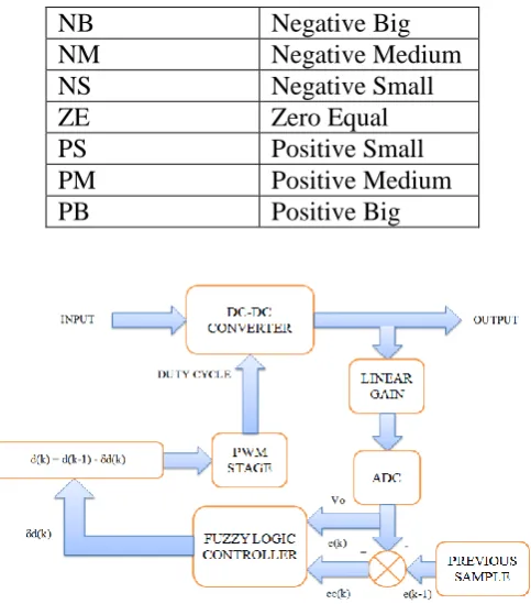
NB
Negative Big
NM
Negative Medium
NS
Negative Small
ZE
Zero Equal
PS
Positive Small
PM
Positive Medium
PB
Positive Big
Fig. 2. Buck-Boost Converter Using Fuzzy Logic Controller
Fuzzifier converts the crisp sets into fuzzy sets. A mamdani type inference method is used for the design of controller. A group of seven fuzzy subsets are used, these are PB,PM,PS,ZE,NS,NM,NB. Using IF-THEN rule, 49 rules are designed in the matrix table and these rules are shown in table1. Defuzzification method used is centroid of gravity. Triangular membership function is used for input (error and change in error) and output. The values are normalized in between [-1,1]with the help of suitable scaling factors. The two inputs can be written as,
e(k) = Vreference – Voutput
ce(k) = e(k) – e(k-1)
Design of fuzzy controllers is based on expert knowledge of the plant instead of a precise mathematical model. There are two inputs for the fuzzy controller for the buck and boost converters. The first input is the error in the output voltage given by (1), where ADC[k] is the converted digital value of the kth sample of the output voltage and Ref is the digital value corresponding to the desired output voltage. The second input is the difference between successive errors and is given above.
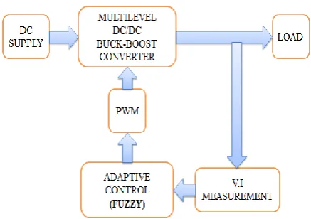
V. PROPOSED SYSTEM
Block Diagram Description
Buck-Boost converter is used and converter level increased upto five level.
Also implemented Closed loop system to reduce the voltage ripples
Duty Cycle <50 = Buck - Converter
Duty Cycle >50 = Boost – Converter
Fig. 3. Block Diagram Of Proposed System
and converts AC to DC Output. The obtained DC Voltage produce ripples and its eliminated by LC Filter. The filter produces pure DC Voltage and fed to the LOAD. Depending upon the Input supply voltage, Converter will be acts as a Buck & Boost Converter.
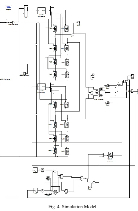
Fig. 4. Simulation Model
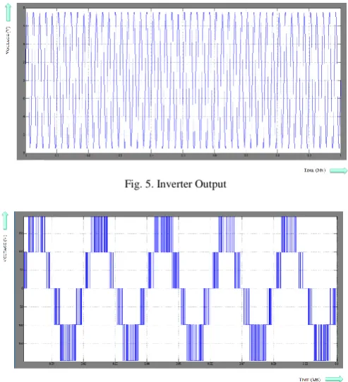
VII. RESULT AND DISCUSSION
Fig. 5. Inverter Output
Fig. 6. Five – Level Inverter Output
BUCK CONVERTER OPERATION :
The input voltage is 430 (V), Output of DC/DC Converter voltage is given to the Fuzzy Logic Controller (FLC). The Reference voltage 230 (V), is set to the fuzzy logic controller. And the controller compares Actual Voltage and Reference Volatge. Difference in Voltage will change the firing angle and duty cycle. Depending upon the Input Voltage Converter will be acts as a Buck & Boost Converter. Finally the Buck Converter output voltage and output current waveforms are obtained. Buck Converter operation table shown below.
Fig. 8. Output Voltage
Fig. 9. Output Current
BOOST CONVERTER OPERATION :
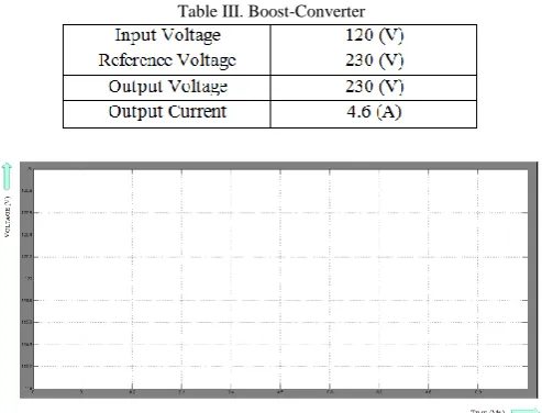
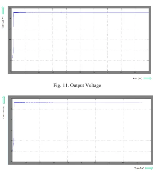
The input voltage is 120 (V), Output of DC/DC Converter voltage is given to the Fuzzy Logic Controller (FLC). The Reference voltage 230 (V), is set to the fuzzy logic controller. And the controller compares Actual Voltage and Reference Voltage. Difference in Voltage will change the firing angle and duty cycle. Depending upon the Input Voltage Converter will be acts as a Buck & Boost Converter. Finally the Boost Converter output voltage and output current waveforms are obtained. Boost Converter operation table shown below.
Table III. Boost-Converter
Fig. 11. Output Voltage
Fig. 12. Output Current
VIII.CONCLUSION
In this paper, Analysis of Buck-Boost Converter with Fuzzy Logic Converter (FLC) is presented. The output voltage of Buck-Boost Converter can be stabilized using variable duty cycle generated by the fuzzy logic controller. Buck-Boost converter with closed loop fuzzy logic controller precisely improved the dynamic response of the system during load as well as source variation with reduced voltage and current ripple. Fuzzy controllers were designed the buck and boost converters. The fuzzy controllers were designed based on the in-depth knowledge of the plant, simulation by Simulink and experimental results. The fuzzy controller for the boost converter uses two different controller configurations for the start up transient and for steady state to obtain a fast and stable response, while only one configuration is used for the buck converter. Fuzzy logic appears to be a valid element for generalization to many control applications. Since both buck and boost converters are controlled using the same fuzzy control algorithm (without any modifications to the program), this shows that the fuzzy controller is developed based on the linguistic description of the system and not its mathematical model. Finally performance analysis of Buck-Boost Converter with fuzzy logic controller has been done by using of MATLAB – Simulink.
[10] R.Anand, and P.Melba Mary,”Comparison of PID and Fuzzy Controlled DC to DC Converter with Inductor Resistance”, International Journal of Engineering Sciences & Research Technology Vol 2, Issue 8, August 2013.
[11] Rem Langari,”Past, Present and Future of Fuzzy Control: A Case for Application of Fuzzy Logic In Hierarchical Control,” IEEE Transaction on Industry applications, pp.760-765, 1999.
[12] V. S. C Raviraj, and P. C. Sen, “Comparative Study of Proportional-Integral, Sliding-Mode, and Fuzzy Logic Controllers for Power Converters,” IEEE transaction on Industry applications, Vol. 33, Issue 2, pp. 518- 524, April 1997.
[13] Abdelfettah Zeghoudi and Ali Chermitti, “A Comparison between a Fuzzy and PID Controller for Universal Motor”, International Journal of Computer Applications, Vol. 104, Issue 6, pp. 0975–8887 October 2014.
[14] Chuen Chien Lee, “Fuzzy logic in control systems i.e. fuzzy logic controller,”IEEE Transactions on Systems, man and cybernetics, Vol20, No.2, March/April 1990.