A New Highly Efficient Three-Phase Transformer-Less
Hbzvr for Grid Operating System
.
Uppala Naresh M-tech Scholar
Department of Electrical & Electronics Engineering, Anurag College of Engineering , Aushapur(Vi),Ghatkesar(Md);
Ranga Reddy (Dt); Telangana, India. Email:[email protected]
Sarala Sandolu Assistant Professor
Department of Electrical & Electronics Engineering, Anurag College of Engineering , Aushapur(Vi),Ghatkesar(Md);
Ranga Reddy (Dt); Telangana, India. Email:[email protected]
Abstract: ABSTRACT-Single-phase transformer less inverter is widely used in low-power grid-connected systems due to its small size, high efficiency and low cost. The galvanic isolation can be achieved via dc-decoupling or ac-decoupling, for isolation on the dc- or ac-side of the inverter, respectively. It has been shown that the latter provides lower losses due to the reduced switch count in conduction path. Common-mode voltage (CMV) appears in motor drives due to working principles of the pulse width modulation (PWM) inverters. This voltage is the main source of many unwanted problems in AC drive systems. In this Project, several recently proposed transformers less inverters with different galvanic isolation methods and CMV clamping technique are analyzed and compared. A simple modified H-bridge zero-voltage state rectifier is also proposed, to combine the benefits of the low-loss ac-decoupling method and the complete leakage current elimination of the CMV clamping method. The performances of different topologies, in terms of CMV, leakage current, total harmonic distortion, losses and efficiencies are compared. The proposed concept is further connected to three-phase system and is implemented using HBZVR concept. A safety issue is the main concern for the transformer less systems due to high leakage current. Without galvanic isolation, a direct path can be formed for the leakage current to flow from the source to the grid by In extension the proposed concept can be implemented for three-phase configuration by using MATLAB/SIMULATION software.
Keywords: Brushless DC Motor (BLDC), Anti-windup PI Controller, Fuzzy controller, Hybrid controller,
speed control, PWM inverter
I. INTRODUCTION
Today, the energy demand is increasing due to the rapid increase of the human population and fast-growing industries. Hence, renewable energy plays an important role to replace traditional natural resources such as fuel and coal. Photovoltaic (PV) energy has recently become a common interest of research because it is free, green, and inexhaustible [1]–[3]. Furthermore, PV systems are now more affordable due to government incentives, advancement of power electronics and semiconductor technology and cost reduction in PV modules [2], [3]. Generally, there are two types of grid-connected PV systems, i.e., those with transformer and without transformer. The transformer used can be high frequency (HF) transformer on the dc side or low frequency transformer on the ac side [4]. Besides stepping up the voltage, it plays an important role in
(a)
(b)
(c)
(d)
(e)
(f)
Fig. 1. Recently proposed transformer less topologies. (a) Diode-clamped topology. (b) H5 topology. (c) HERIC topology. (d)
oH5 topology. (e) H6 topology. (f) HBZVR topology.
state rectifier (HBZVR), as shown in Fig. 1(d)–(f), to completely eliminate the leakage current. However, the clamping branch of HBZVR does not perform optimally. It is shown in the later section that the leakage current is as high as those of galvanic isolation topologies. In this paper, several recently proposed transformer less PV inverters with different galvanic isolation methods and CMV clamping techniques, as shown in Fig. 1, are analyzed and compared. A simple modified HBZVR-D is also proposed, to combine the benefits of the low-loss ac-decoupling method and the complete leakage current elimination of the CMV clamping method. Performance of HBZVR-D is compared to other existing topologies in terms of CMV, leakage current, total harmonic distortion (THD), losses analysis, and efficiency. Discussions are done based on MATLAB/Simulink simulations and further validated through experimental tests. It is proven that HBZVRD topology gives the best overall performance and is
suitable for transformer less PV applications.
Simulation and experimental results are shown in Section IV and Section V, respectively, to validate and discuss the performance of various topologies. Finally, conclusion is made in Section VI to summarize the findings and results.
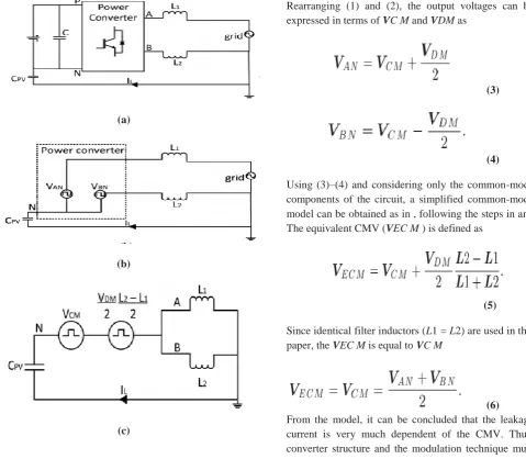
II. COMMON-MODE BEHAVIOR AND LEAKAGE CURRENT REDUCTION METHODS
When the transformer is removed from the inverter, a resonant circuit is formed as shown in Fig. 2(a). This resonant circuit includes stray capacitance (CP V ), the filter inductors (L1 and L2), and leakage
current (IL). Here, the power converter is represented
by a block with four terminals to allow a general representation of various converter topologies. On the dc side, P and N are connected to the positive and negative rail of the dc-link, respectively; while on the ac side, terminals A and B are connected to the single-phase grid via filter inductors. From the view point of the grid, the power converter block shown
(a)
(b)
(c)
Fig. 2. Common-mode model for single-phase grid-connected inverter. (a) Full model. (b) Simplified model. (c) Simplified
common-mode model.
in Fig. 2(a) can be considered as voltage sources,
generating voltage VAN and VBN . Hence, regardless of
the conversion structure, this power converter block can be simplified into the equivalent circuit which consists
of VAN and VBN as shown in Fig. 2(b) . The leakage
current is thus a function of VAN, VBN , grid voltage,
filter inductance, and stray capacitance. The CMV VC
M and differential-mode voltage VDM can be defined
as
(1)
(2)
Rearranging (1) and (2), the output voltages can be
expressed in terms of VC M and VDM as
(3)
(4)
Using (3)–(4) and considering only the common-mode components of the circuit, a simplified common-mode model can be obtained as in , following the steps in and
The equivalent CMV (VEC M ) is defined as
(5)
Since identical filter inductors (L1 = L2) are used in this
paper, the VEC M is equal to VC M
be designed to generate constant CMV in order to eliminate the leakage current. It is worth highlighting that the model in Fig. 2(c) has been commonly used for describing the common-mode behaviour of the conventional full-bridge (H4) topology. However, due to the generality of the model, it is obvious that the model is valid for other topologies discussed here, apart from H4. As a matter of fact, the same model has been used to analyze the common-mode behaviour of various transformers less converter topologies. However, since
different topology has different VAN and VBN , the
expressions for VC M and VDM will differ from one
another, which yield different common-mode
behaviour.
Fig. 3. Universal transformerless topologies.
Hence, to evaluate the common mode behaviour of a
particular topology, VAN and VBN under different
switching condition need to be evaluated, as will be shown later.
A. Galvanic Isolation In transformer less PV inverters, the galvanic connection between the PV and the grid allows leakage current to flow. Hence, in topologies such as H5 and HERIC, galvanic isolation is provided to reduce the leakage current. The galvanic isolation can basically be categorized into dc-decoupling and ac-decoupling methods. For ac-decoupling method, dc-bypass switches are added on the dc side of the inverter to disconnect the PV arrays from the grid during the freewheeling period. However, the dc-bypass branch, which consists of switches or diodes, is included in the conduction path as shown in Fig. 3. For H6, output current flows through two switches and the two dc-bypass branches during the conduction period. Hence, the conduction losses increase due to the increased number of semiconductors in the conduction path. On the other hand, bypass branch can also be provided on the ac side of the inverter (i.e., ac-decoupling method) such as seen in HERIC. This ac-bypass branch functions as a freewheeling path which is completely
isolated from the conduction path, as shown in Fig. 3. As a result, the output current flows through only two switches during the conduction period. Therefore, topologies employing ac-decoupling techniques are found to be higher in efficiency as compared to dc-decoupling topologies. One setback of galvanic isolation is that there is no way of controlling the CMV by PWM during the freewheeling period. Fig. 4 shows operation modes of galvanic isolation which
(a)
(b)
Fig. 4. Operation modes of dc-decoupling topology. (a) Conduction mode and (b) freewheeling mode
employs dc-decoupling method. As shown in Fig. 4(a),
during the conduction period, S1 and S4 conduct to
generate the desired output voltage. At the same time,
VA is directly connected to VDC and VB is connected
to the negative terminal (N) of the dc-link. Hence, the CMV becomes
(7) Nevertheless, during the freewheeling period, the dc-bypass switches disconnect the dc-link from the grid.
Therefore, point A and point B are isolated from the
dc-link, and VA and VB are floating with respect to the
instead, is oscillating with amplitude depending on the parasitic parameters and the switches’ junction capacitances of the corresponding topology. As a result, leakage current can still flow during freewheeling period. The same is the case for converters using ac
decoupling method
B. CMV Clamping As mentioned earlier, CMV is one of the main causes for leakage current. H5 and HERIC focus only on providing galvanic isolation while neglecting the effect of the CMV. Unlike conventional topologies, the CMV in these topologies cannot be manipulated via PWM, due to the use of galvanic isolation as explained previously. In order to generate constant CMV, clamping branch is introduced in oH5 [see Fig. 1(d)] and H6 [see Fig. 1(e)].
(a)
(b)
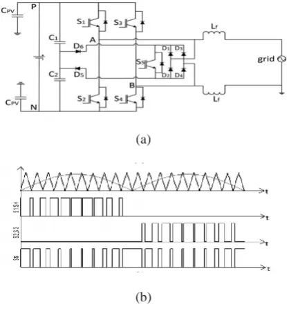
Fig. 5. Proposed HBZVR-D topology. (a) Converter structure. (b) Switching waveforms
Generally, the clamping branch consists of diodes or switches and a capacitor divider which ensures the freewheeling path is clamped to the half of the input voltage. With the combined effect of galvanic isolation and CMV clamping, leakage current is completely eliminated. Nevertheless, both H6 and oH5 uses dc-decoupling method, which suffers from lower efficiency. HBZVR also employs CMV clamping technique but it is found that the clamping branch does not function optimally. It is shown in both the simulation and experimental results that the CMV and the leakage current in HBZVR are as high as those in the topologies which use only galvanic isolation.
III. OPERATION PRINCIPLES OF PROPOSED TOPOLOGY
A. Structure of Proposed HBZVR-D
Based on the analysis above, a simple modified HBZVR-D is proposed to combine the benefits of the low-loss ac-decoupling method and the complete leakage current elimination of the CMV clamping method. HBZVR-D is modified by adding a
fast-recovery diode, D6, to the existing HBZVR as shown in
Fig. 5(a). The voltage divider is made up of C1 and C2.
S1−S4 are the switches for full-bridge inverter. The anti
parallel diodes, D1−D4, as well as S5 provide a
freewheeling path for the current to flow during the
freewheeling period. Diodes D5 and D6 form the
clamping branches of the freewheeling path.
B. Operation Modes and Analysis In this section, the operation modes and the CMV of the proposed topology is discussed. Fig. 5(b) illustrates the switching
(a)
(c)
(d)
Fig. 6. Operation modes of proposed HBZVR-D topology. (a) Mode 1—conduction mode and (b) Mode 2—freewheeling mode during positive half cycle. (c) Mode 3—conduction mode and (d) Mode 4—
freewheeling mode during negative half cycle.
patterns of the proposed HBZVR-D. Switches S1−S4
commutate at switching frequency to generate unipolar
output voltage. S5 commutates complementarily to
S1−S4 to create freewheeling path. All the four
operation modes are shown in Fig. 6 to generate unipolar output voltage. In mode 1, S1 and S4 are ON
while S2,S3 and S5 are OFF. Current increases and
flows through S1 and S4. VAB = +VDC . The CMV
becomes
(8)
In mode 2, S1−S4 are OFF. S5 is ON to create a
freewheeling path. Current decreases and freewheels
through diodes D3,D2, and the grid. The voltage VAN
decreases and VBN increases until their values reach the
common point, VDC /2, such that VAB = 0. The CMV
is
(9)
In mode 3, S2 and S3 are ON, while S1,S4 and S5 are
OFF. Current increases and flows through S2 and S3.
VAB = −VDC . The CMV becomes
(10)
In mode 4, S1−S4 are OFF. S5 is ON to create
freewheeling path. Current decreases and freewheels
through diodes D1,D4, and the grid. The voltage VAN
decreases and VBN increases until their values reach the
common point, VDC /2, and VAB = 0. The CMV is as
derived in (10). Obviously, modulation techniques are designed to generate constant CMV in all four operation modes. All the research works are designed based on
the principles above. Practically, VAN and VBN do not
reach common point during the freewheeling period (mode 2 and mode 4). It is shown in simulation and experimental results later that the CMV is not constant without clamping branch. During the freewheeling
period, both VAN and VBN are not clamped to VDC /2
and is oscillating with amplitude depending on the parasitic parameters and junctions’ capacitance of those topologies. The improved clamping branch of
HBZVR-D ensures the complete clamping of CMV to VDC /2
during the freewheeling period. It is well noted that the output current flows through only two switches in every conduction period (mode 1 and mode 3) as shown in Fig. 6(a) and (c). This explains why HBZVR-D has relatively higher efficiency than those of dc-decoupling topologies.
C. Operation Principles of Improved Clamping Branch
During the freewheeling period, S5 is turned ON,
connecting point A and B. Freewheeling path voltage VF P can be defined as VF P =VAN ≈VBN , since the
voltage drops across diodes and S5 are small compared
to VDC . There are two possible modes of operation
(mode 2 and mode 4 as shown in Fig. 6) depending on
whether D5 or D6 is forward biased. When VF P is
greater than VDC /2, D5 is forward biased and D6 is reversed biased. Current flows from the freewheeling path to the midpoint of the dc-link via the clamping
diode D5, as shown in Fig. 6(b), which completely
clamps the VF P to VDC /2. On the other hands, when
the VF P is less than VDC /2, D6 is forward biased and
D5 is reversed biased. As shown in Fig. 6(d), current
flows from the midpoint of the dc-link to the
freewheeling path via the added clamping diode D6, to
increase the VF P to VDC /2. It should be noted that during the dead time between the conduction period and freewheeling period, the freewheeling path is not well-clamped and the CMV can be oscillating with the grid voltage. Nevertheless, with proper selection of dead time, this effect can be minimized. In HBZVR, the
clamping branch consists of D5 only. Thus, the
clamping of the freewheeling path is limited only for
the period when VF P is more than VDC /2. When VF
function because D5 is reversing biased. During such condition, the CMV in HBZVR will oscillate, causing the flow of leakage current. This setback is rectified by
adding a fast-recovery diode D6 in the proposed
HBZVR-D topology. With both D5 and D6, the
improved clamping branch guarantees the complete
clamping of the CMV to VDC /2 throughout the
freewheeling period. As a result, leakage current, which is very much dependent on CMV, is completely eliminated.
IV. SIMULATION RESULTS
A) Simulation block diagram:
Fig 7 Matlab/Simulation circuit of single-phase full bridge controller
Fig 8 simulation wave form of grid voltage and current leakage current, neutral line voltage
Fig.9. Matlab/simulation proposed circuit of three-phase controller
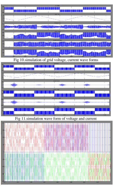
Fig 10.simulation of grid voltage, current wave forms
Fig 11.simulation wave form of voltage and current
Fig 12.simulation wave form of three-phase grid voltage,
Fig 13. Simulation wave form of three-phase grid current
Fig 14.simulation wave form of three-phase current and voltage
V. CONCLUSION
The simulation results are compared with Hybrid controller results. Anti-windup PI controller, results are slower compared to Three-Phase. From the simulation results, it is clear that for the load variation and speed variation hybrid controller gave better response than Anti-windup PI controller. Hence hybrid controller is found to be more suitable for Three-Phase during speed variation and load variation.
VII.REFERENCES
[1] F. T. K. Suan, N. A. Rahim, and H. W. Ping, ―Modelling, analysis and control of various types of transformer less grid
connected PV inverters,‖ in Proc. IEEE Clean Energy
Technol., Jun. 2011, pp. 51–56.
[2] N. A. Rahim, K. Chaniago, and J. Selvaraj, ―Single-phase seven-level grid connected inverter for photovoltaic system,‖
IEEE Trans. Ind. Electron., vol. 58, no. 6, pp. 2435–2443,
Jun. 2011.
[3] G. Petrone, G. Spagnuolo, R. Teodorescu, M. Veerachary, and M. Vitelli, ―Reliability issues in photovoltaic power processing systems,‖ IEEETrans. Ind. Electron., vol. 55, no. 7, pp. 2569–2580, Jul. 2008.
[4] M. Calais, J. Myrzik, T. Spooner, and V. G. Agelidis, ―Inverters for single phase grid connected photovoltaic system – an overview,‖ in Proc. IEEEPower Electron. Spec. Conf., 2002, pp. 1995–2000.
[5] J. M. Shen, H. L. Jou, and J. C. Wu, ―Novel transformer less grid connected power converter with negative grounding
for photovoltaic generation system,‖ IEEE Trans. Power
Electron., vol. 27, no. 4, pp. 1181– 1829, Apr. 2012.
[6] S. V. Araujo, P. Zacharias, and R. Mallwithz, ―Highly efficient single phase transformer less inverters for
grid-connected photovoltaic systems,‖ IEEE Trans. Ind. Electron.,
vol. 57, no. 9, pp. 3118–3128, Sep. 2010.
[7] O. Lopez, F. D. Freijedo, A. G. Yepes, P. Fernandez-Comesaa, J. Malvar, R. Teodorescu, and J. Doval-Gandoy, ―Eliminating ground current in a transformer less photovoltaic application,‖ IEEE Trans. Energy Convers., vol. 25, no. 1, pp. 140–147, Mar. 2010. [8] T. Kerekes, R. Teodorescu, M. Liserre, C. Klumpner, and M. Sumner, ―Evaluation of three-phase transformer less
photovoltaic inverter topologies,‖ IEEE Trans. Power
Electron., vol. 24, no. 9, pp. 2202–2211, Sep. 2009.
[9] B. N. Alajmi, K. H. Ahmed, G. P. Adam, and B. W. Williams, ―Singlephase single-stage transformer less
grid-connected PV system,‖ IEEETrans. Power Electron., vol. 28,
no. 6, pp. 2664–2676, Jun. 2013.
[10] Y. Gu, W. Li, Y. Zhao, B. Yang, C. Li, and X. He, ―Transformer less inverter with virtual DC bus concept for
cost-effective grid-connected PV power systems,‖ IEEE
Trans. Power Electron., vol. 28, no. 2, pp. 793–805, Feb.
2013.
[11] D. Meneses, F. Blaabjerg, O. Garc´ ıa, and J. A. Cobos, ―Review and comparison of step-up transformer less
topologies for photovoltaic ac-module application,‖ IEEE
Trans. Power Electron., vol. 28, no. 6, pp. 2649–2663, Jun.
2013.
[12] L. Zhang, K. Sun, L. Feng, H. Wu, and Y. Xing, ―A family of neutral point clamped full-bridge topologies for transformer less photovoltaic grid-tied inverters,‖ IEEE Trans.
Power Electron., vol. 28, no. 2, pp. 730–739, Feb. 2013.
AUTHORS:
Uppala Naresh received B-tech from Ellnnki College of Engineering in the year 2013 and now pursuing M.Tech in the stream of Electrical power systems at Anurag College of Engineering