An Economical Battery Charger for Small
Wind Turbines
Daniel T VArghese1, Arun S2
M.Tech Scholar, Dept. of EEE, Amal Jyothi College of Engineering, Kerala, India1
Professor, Dept. of EEE, Amal Jyothi College of Engineering, Kerala, India2
ABSTRACT:Small wind turbines is now becoming common source of electrical power generation in rural sites around the world. The power generated by a Small wind turbine at a given wind speed is a non-linear function of rotor speed. A control system incorporating a Pulse Width Modulated DC - DC converter has to be designed to vary the load on the wind turbine thereby forcing it to operate at its maximum power point. The converter is designed is designed to enable fast battery charging. Also due to lack of service problem and customer demand a battery charger at multiple DC levels is required. So simple reliable and economical battery charger using multiphase is designed and setup. The converter control is done using PIC microcontroller. Simulation results and hardware results validates that it is by far the most efficient circuit for battery charging in renewable circuit were the load variation is drastic
KEYWORDS:PWM, Multiphase, Wind Turbine.
I.INTRODUCTION
One of the frequently mentioned drawbacks of renewable energy technologies is that they cannot supply electricity consistently. Energy from the wind and sunlight are variable resources. It is possible to get wind power when the wind blows. That is the reason for the popularity of stand-alone systems. By charging batteries, it can be ensured that electricity is present at the time it is needed, even if the wind is not blowing the turbine or the sun is not shining on the PV panels [1]. Using several batteries connected into battery banks some homeowners have succeeded in taking their homes off grid. This means they are no longer connected to the electric transmission grids. These homes provide electricity using wind turbines, solar panels, and or diesel generators. They store excess energy in battery banks to ensure that they have enough electricity to get them through a few days without wind or sun.
However, because of the extensive interconnection of the converters, a large variety of dynamic interactions is possible. This might impact power quality and system stability. Most of the research studies reported in the literature are mainly related to studying of an individual converter for its stand-alone operation [2]. Yet, the dynamics associated with the multi-converter systems and related issues such as modelling, design, control, and stability assessment are not widely known.Even if there are power electronic converters for charging the batteries, the time taken for battery charging is very slow. Thus the effective and efficient use of the available power will not happen. The wind availability is intermittent so a system which can charge batteries at faster rate will always add to the advantage of the existing system. It will also improve the efficiency of the complete renewable energy system [2]. This was the motivation behind the mini project work that is to develop a fast charging battery scheme for wind energy conversion systems in renewable energy.A small wind turbine conversion system becomes effective only if it is robust and economical at the battery level.Thus the work aims at producing an economical fast charging DC-DC converter for battery charging at multiple voltage levels.
II. LITERATURE REVIEW
The Figure 1 gives an overall idea of the small wind turbine forecast in the world till 2020. We can see that the graph is steadily increasing. So now let us discuss some of the existing schemes that are used for wind energy conversion systems.
Stand Alone Wind system With MPPT The below Figure 2 depicts a standalone wind turbine system. This system incorporates MPPT technique for improving the overall system efficiency [6]. It consists of rectifier at the turbine output to convert AC power to DC.
DC-DC CONVERTER
DC-DC conversion technology is a major subject area in the field of power electronic, power engineering and drives. The simplest DC-DC conversion technology is a voltage divider, potentiometer and so on [4]. But the effect of these simple conversion techniques resulted in poor efficiency due to fact that transfer output voltage is lower than the input voltage. There have been more than 500 prototypes of DC –DC converter developed for more than 60 years [4]. Non-isolated DC to DC converters are advantageous since they yield high efficiency and do not require as much space as that of the isolated topologies [5]. There are three widely used non-isolated topologies used for stepping up or down
Figure 1 Small Wind Turbine World Market [2] Forecast
DC voltage. Buck converters step down voltage while Boost converters step up voltage. Buck-Boost converters may be used to either step up or step down voltage. All three topologies cost approximately the same to build and use approximately the same space per given output power.
Cascaded Boos Buck For wind energy conversion
The cascaded boos buck converter provides the control of the wind generator for a wide variety of speed [9]. A typical circuit used for standalone wind power generation is shown in Figure 3
Disadvantage of this system is its control is complex.The system lacks in fast charging of battery.Thus for battery charging of small wind turbine a simple low cost economical battery charger is required. The battery charger should be capable of charging the batteries with less charging time. The issue for fast battery charging can thus be rectified by the development of multiphase battery charging circuit. It consists parallel chopper providing higher charging current for the battery.
III.MULTIPHASE CONVERTER
Multiphase converter consists of two or more switches connected in parallel. A two switch topology is as shown in Figure 4. In this converter configuration the inductance in series with the switches are assumed to be sufficiently large and hence each switches operates independently of each other [12].
From the above studies it is clear that phase shifted operation is preferred for the battery charging system. The converter was designed to operate in two operating states one giving a 12 Volt battery charging and the other with 24
Figure 3 Cascaded Power Converter [9]
+
V
0V
dL
1L
2D
2D
1C
S2
S
1R
+
Volt battery charging. For the analysis of phase shifted mode of the battery charging circuit, the converter is analysed by two states. The two states are as follows.
MODE 1
=−
= −
In this mode the switch S1 is turned OFF and the parallel chopper is present in the circuit [12]. It acts as simple buck converter and the parallel circuit freewheels through the diode D2.
MODE 2
=−
= −
In this mode the switch S2 is turned OFF and the parallel chopper is present in the circuit. It acts as simple buck converter and the parallel circuit freewheels through the diode D1.
Thus from the derivation it is clear that it is step down converter. Since the current is doubled the battery charging system will be more effective. Here Vs,Vo , Vl1 , Vl2Ts , D are input supply, output voltage, Inductor1 voltage, Inductor 2
voltage, switching frequency, and duty ratio respectively. Similarly the inductor design is derived from the following ripple current equation.
+
V
0V
dL
1L
2D
2D
1C
S2
R
+
Figure 4. Multiphase Battery charger mode 1
+
V
0V
dL
1L
2D
2D
1C
S
1R
+
IV.SIMULATION RESULTS
A multiphase converter was analysed by MATLab Simulink model. The circuit parameters for the simulation are listed in Table1. The steady state behaviour of the multiphase converter was analysed in open loop. The Simulink model is shown in Figure 7
PARAMETERS ATTRIBUTES Input Supply 30V
Inductor (L1) 4.49mH
Inductor (L2) 3.63mH
Output Resistance 4ohm
Filter Capacitor 150µF
The gate pulse for the signal is as shown in Figure 8 and the Simulink model for the multiphase converter is shown in Figure 7. The model has been framed by an open loop control scheme as it was required for analysis. The simulation analysis was carried out
Table 1 Circuit parameters
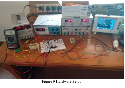
The hardware setup of the converter is shown in figure 9. The circuit analysis was carried out by doing comparative studies with a simple buck converter. The circuit studies were further completed using variable duty ratio analysis.
V. ANALYSIS
To do comparative study certain analysis were carried out it consists of variable duty analysis this was done by varying the duty of one switch at a time. The analysis was done to make sure that the charging time was reduced from that of conventional buck converter. At first the frequency was fixed and duty ratio was varied for the two switches and the results are as follows.
Variable Duty ratio Analysis
Output Voltage Comparison
Figure 8 Gate pulse
The figure 10 shows the variable duty ratio plot and the analysis clearly indicates that the current is rising and it is helpful for fast battery charging.
The figure 11 shows the variable duty ratio analysis it clearly indicates that the circuit is efficient and provide fast battery charging than previous converters.
VI.CONCLUSION
From the studies conducted with the individual buck circuit for 12V and 24V system there is a prominent increase in output current. The multiphase chopper circuit for battery charging is thus effective and economical. The analysis results clearly support the statements for fast battery charging. This system prove to improve the efficiency of the renewable energy system as a whole because it aids to nullify the problem of intermittency of renewable source. The end results of the analysis are as follows.For a 12V battery charger the individual buck system worked with an output current of 1.3A whereas the multiphase charge circuit worked with a current of 3.6A. Similarly for the 24V system the
5.8 5.85 5.9 5.95 6 6.05 6.1 6.15 6.2 6.25
0% 20% 40% 60% 80% 100%
individual system offered a current of 4.5A and the multiphase converter gave 6.2A. And with the developed system an overall efficiency of 97.2% and 96.6% were achieved for 12V and 24V system respectively
REFERENCES
[1] V I Cherian, Daniel T Varghese,, “ Analysis and study on small hydro wind systems” International Journal For Technological Research in Engineering, Vol 2, No:8, April 2015
[2] Chetan Singh Soalnki:, “ Solar Photovoltaics” PHI Learning Pvt Ltd, Fourth edition, Haryana,2013
[3] E. Koutroulis and K. Kalaitzakis:,“ Novel battery charging regulation for Photovoltaic systems” IEE Proc.-Electr. Power Appl., Vol. 151, No. 2, March 2004.
[4] M. Druga, C. Nichita:, “ Stand Alone Wind power System operating with specific storage structure”, International Conference on Renewable Energies and Power Quality, April 2009
[5] Herminio Martínez-Garcia, Haritha Eachempatti :,“On Chip SIDO Buck converter with independent outputs” Conference on the Design of Circuits and Integrated Systems, Nov 2013
![Figure 4. Multiphase Battery charger [12]](https://thumb-us.123doks.com/thumbv2/123dok_us/7787109.1288694/3.595.160.411.525.717/figure-multiphase-battery-charger.webp)