Design & Analysis of a Modified Circular
Microstrip Patch Antenna with Circular
Polarization and Harmonic Suppression
Lokesh K. Sadrani
1, Poonam Sinha
2PG Student (MMW), Dept. of ECE, UIT Barkatullah University Bhopal, Madhya Pradesh, India1
Professor & Head, Dept. of ECE, UIT Barkatullah University Bhopal, Madhya Pradesh, India2
ABSTRACT: In this paper a circular microstrip patch antenna with embedded circular slots to obtain harmonic suppression and peripheral cuts for producing circular polarization (CP) is proposed and analyzed. Antenna is designed by taking into consideration the use of Active Integrated Antennas [1] and rectifying antennas (rectenna) [2]. Low cost FR4 epoxy is used as the substrate and 2.45GHz/802.11a as the design frequency. Simulated 10dB return loss bandwidth of 171MHz and CP 3dB axial ratio bandwidth of 46MHz is obtained. Size reduction of 4% is also obtained as compared to the conventional circular patch antenna with linear polarization (LP). Simulations and optimizations are performed by using High Frequency Structure Simulator (HFSS) software.
KEYWORDS: Circular Patch, Rectenna, Harmonic Suppression, Circular Polarization, HFSS.
I. INTRODUCTION
Active Integrated Antennas and rectifying antennas (rectenna) applications in millimeter wave range are getting much attention in recent years especially in the field of power combining, beam steering and switching, and high efficiency power amplifiers. Rectennas were earlier proposed for high power transmission [3]. Nowadays application of rectennas in low power RFID tags, proximity cards, and contactless smart cards is well known. These applications lies within the
allowed electromagnetic radiation power levels. Distance between electromagnetic source and antenna is within 5cms
[4]. Using a passive RFID tag makes the system more cost effective as the need for power supply to the tags will be eliminated by using rectenna. Proximity cards and contactless smart cards have become quite popular in ticketing and easy money payment systems. Delhi metro uses [5] cards which are rectenna based cards and which can be used without even removing the card from wallet or bag. In this paper a circular microstrip patch antenna with embedded circular slots to obtain harmonic suppression and peripheral cuts for producing circular polarization (CP) is proposed and discussed.
Design of a rectenna/AIA has two fundamental requirements: 1. Power added efficiency,
2. Position independent use.
First of these requirements has four major areas of concern: 1. Size of antenna,
2. Harmonics generated from non-linear rectifying circuits (Schottky diode or FET), [9] 3. Tuning circuits added to suppress these harmonics which causes extra insertion loss [4], 4. Easy integration with the circuit where it is used.
All these concerns can be taken care of by making a compact slotted patch antenna [9] which is capable of suppressing the harmonics without any extra added circuits and generates circular polarization (CP) to ease us of the angular position requirement of linearly polarized antennas. Simulation software High Frequency Structure Simulator (HFSS) is used to design, and simulate the proposed antenna.
Yu-Jiun Ren et al. (2007), T. C. Yo et al.(2008), and S. Riviere et al. (2010) have proposed antennas with attached filtering circuits for rectenna. But addition of filter circuits lead to extra insertion losses; which again can degrade power efficiency of rectenna. To overcome this problem F. J. Huang et al. (2012) had proposed a patch antenna with inbuilt harmonic suppression capability; which eliminates the filter circuit. Designs of T. C. Yo et al., F. J. Huang et al. and Ren, Yu-Jiun et al. are circular polarization rectenna designs. Circular polarization enables the antenna to receive electromagnetic power from signal with any polarization; which is suitable for rectenna application [9]. This paper proposes an antenna for rectenna which has both inbuilt harmonic suppression and circular polarization features.
II. ANTENNA DESIGN & OPTIMIZATION
While designing a circular microstrip antenna taking into account the fringing [9,10] the equation for the radius of the circular patch becomes
a = F
1+ 2h
π εr F ln π F
2h +1.7726
1 2 , where F =
8.791×10⁹
fr εr (1)
h=height of the substrate,
εr=dielectric constant of substrate
Initial calculations based on the above design formulae (1) for the basic circular microstrip antenna is given in Table 1.
Substrate Material
Resonant frequency fr(GHz)
𝜺𝒓 Radius of patch
R(in mm)
Height of substrate h(in mm)
Feeding point location (xf, yf)in mm
FR4 2.45 4.4 16.60776455 1.6 (7.8, 0)
Table 1: Calculations for radius of basic circular patch antenna.
Feeding point is obtained from HFSS optimization for 50Ω terminal impedance to avoid use of any impedance matching network between patch and coaxial cable [3,4,5]. Feed point is optimized so that it must exhibit a terminal impedance equal to the characteristic impedance of a coaxial cable (50 Ω).
R 16.598mm
L 42.796mm
W 42.796mm
Fx 7.8mm
Cd 12mm
Cw 4.346mm
Sr 6.5mm
Sw 0.102mm
Fig. 1 Proposed circular microstrip antenna for circular polarization and harmonic suppression at 2.45GHz
Fig.1 shows the proposed antenna with two peripheral cuts and three circular slots. Which is a circular microstrip patch
obtain RHCP the 45° line has to be shifted at a position which is mirror image of that used in LHCP at vertical plane [6-9].
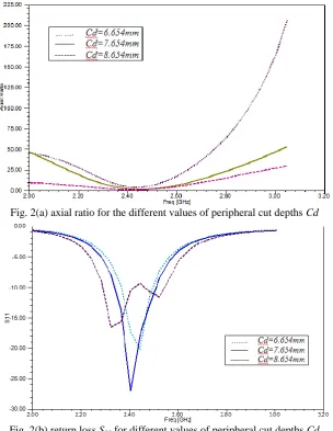
Fig. 2(a) axial ratio for the different values of peripheral cut depths Cd
Fig. 2(b) return loss S11 for different values of peripheral cut depths Cd
Fig. 2(a) shows the axial ratio vs. frequency for different values of cut depths Cd and Fig. 2(b) shows the S11 plots for
different values of cut depths Cd. From these graphs the optimum Cd=7.654 mm is selected as axial ratio value at
resonant frequency is below 3dB level and at the same time S11 values are well below the -10dB level.
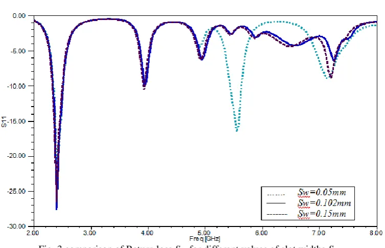
Fig. 3 comparison of Return loss S11 for different values of slot widths Sw.
Fig. 3 shows the plots of return loss for different values of slot widths Sw. From this figure optimum Sw =0.102mm is
selected as the S11 plot shows very little 2
nd
and 3rd harmonic components and excellent S11 results at fundamental
frequency.
III. RESULTS & DISCUSSION
Final antenna design obtained after parametric and optimization analysis through HFSS simulations exhibits both circular polarization and harmonic suppression properties as shown in S11 plot of Fig. 4. Due to change in path length
of current on the patch new resonant frequency of the proposed antenna becomes 2.4027GHz. That means for the same
Fig.4 shows that S11 values for 2nd harmonics (4.9GHz) is only -5.98dB and that for 3rd harmonic (7.35GHz) is only 7.97dB which are below -10dB level. That means there is no significant radiation at 2nd and 3rd harmonics from the proposed antenna.
Fig. 5 simulated axial ratio vs. frequency for the proposed circular patch antenna.
Fig.5 shows the axial ratio vs. frequency for the proposed antenna. Axial ratio values in the plot clearly indicate the presence of circular polarization as the axial ratio curve passes the 3dB level near the design frequency of 2.45GHz. This design is for generating Left Hand Circular Polarization (LHCP); to get RHCP the position of the peripheral cuts has to be shifted at a position which is the mirror image at a plane passing through a vertical line from the centre of the
circular patch. From Fig. 4 -10dB return loss bandwidth obtained is 174.3MHz (7.3%) and from Fig. 5 3dB axial ratio
bandwidth is 46.1MHz.
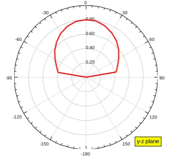
Fig. 6 radiation patterns at x-z and y-z plane.
Fig. 6 shows the radiation pattern at x-z and y-z planes obtained from the proposed antenna; which shows that the radiation pattern is symmetrical about the line perpendicular to the plane of the antenna.
2.00 2.20 2.40 2.60 2.80 3.00 3.20
Freq [GHz] 0.00 10.00 20.00 30.00 40.00 50.00 60.00 Axi a l R a ti o
Curve Info 3 dB BW(2) mag(AxialRatioValue)
Fig. 7 Surface current density of the proposed circular patch.
Fig. 7 shows that the presence of slots are disturbing the current path in such a way so as to increase the path length leading to reduction in resonant frequency; which is equivalent to reduction in overall size of the patch itself.
S.No. Property Conventional Circular Patch Proposed Circular Patch
1. Return Loss(S11) -23.9476dB -29.667dB
2. VSWR 1.6688 1.067
3. Terminal Impedance 62.3843 50.6107
4. Bandwidth(10dB return loss) 121.8MHz (4.97%) 174.3MHz (7.3%)
5. Bandwidth(3dB AR) - 46.2MHz
6. 2nd harmonic S11 -10.3734dB -6.2865dB
7. 3rd harmonic S11 -7.1517dB -6.5478dB
8. Resonant frequency for patch radius
of 1.6598mm
2.45GHz 2.4037GHz
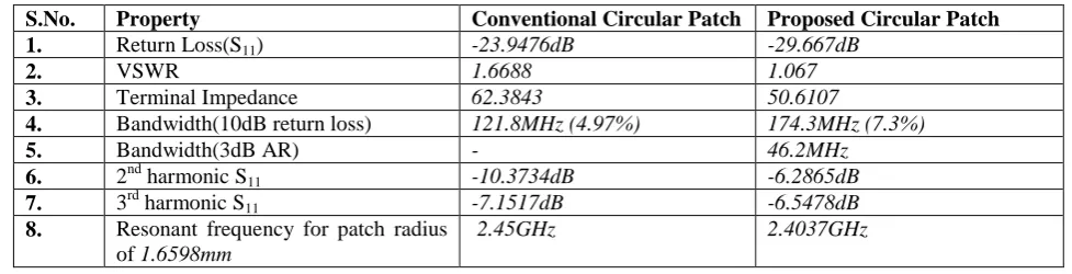
Table 2 Comparison between conventional and proposed circular patch.
Table 2 gives the comparison of some of the parameter values of conventional and proposed circular patch antenna.
Circular patch with three circular slots and peripheral cuts shows good fundamental return loss of -29.667dB which is
greater than that of a basic circular patch. VSWR value of 1.067 is observed from the simulation result which is an improvement of 36% over that of basic design value. Terminal impedance close to 50Ω is obtained as compared to 62Ω terminal impedance of basic design, which means 50Ω coaxial cable is suitable for feeding with less impedance
mismatch. Bandwidth improvement of 2% is obtained in the proposed design as compared to the basic design. 2nd and
3rd harmonics obtained are within the limits of -10dB. Resonant frequency of the proposed antenna has become
2.4037GHz from 2.45GHz which is equivalent to reduction in size of the patch.
IV. CONCLUSION
Proposed design with peripheral cuts and three circular slots has been designed which exhibits excellent gain at
fundamental frequency (-29.6677 dB return loss) while suppressing 2nd and 3rd harmonic (return loss of -6.2865dB and
-6.5478dB respectively) without affecting the circular polarization (3dB axial ratio bandwidth of 46.2MHz around center
REFERENCES
[1] K. Chang, R. A. York, P. S. Hall, and T. Itoh, “Active integrated antennas,” IEEE Trans. Microwave Theory Tech., vol. 50, no. 3, pp. 937–944, Mar. 2002.
[2] W. C. Brown, 'The History of Power Transmission by Radio Waves," IEEE Tran., Microwave Theory Tech., vel. MTT.32, pp. 1230-1242, Sep. 1984.
[3] Torrey, Lee "A trap to harness the sun". New Scientist (London: Read Business Information) 87 (1209): 124–127, Jul 10, 1980. [4] Reid, Robert N. “Facility manager's guide to security: protecting your assets” The Fairmont Press. pp. 144–146. 2005.
[5] http://www.delhimetrorail.com/whatnew_details.aspx?id=axxd290CIsUlld
[6] S. Riviere, F. Alicalapa, A. Douyere, and J. D. Lan Sun Luk, “A Compact Rectenna Device At Low Power Level”, Progress In Electromagnetics Research C, Vol. 16, 137-146, 2010
[7] T. C. Yo, C.M. Lee, C.M. Hsu, and C. H. Luo, “Compact circularly polarized rectenna with unbalanced circular slots,” IEEE Trans. Antennas Propagation, vol. 56, no. 3, pp. 882–886, Mar. 2008.
[8] Ren, Yu-Jiun, Muhammad F. Farooqui, and Kai Chang. "A compact dual-frequency rectifying antenna with high-orders harmonic-rejection." Antennas and Propagation, IEEE Transactions on 55.7 (2007):2110-2113.
[9] F. J. Huang, T. C. Yo, C. M. Lee, and C. H. Luo, “Design of Circular Polarization Antenna with Harmonic Suppression for Rectenna Application” , IEEE Antennas And Wireless Propagation Letters, Vol. 11, 2012