Voltage Sag Compensation in PV Based DVR
Using Fuzzy Controller
B.Pavitra1, C.Santhana Lakshmi2
PG Scholar, Department of EEE, Sona College of Technology, Salem, TamilNadu, India1 Assistant Professor (Sr.G), Department of EEE, Sona College of Technology, Salem, TamilNadu, India2
ABSTRACT: This work presents the mitigation of one of the power quality issues such as the voltage sag occurring in
the photovoltaic system using Dynamic Voltage Restorer (DVR). Simulation results of Photo Voltaic system (PV), Dynamic Voltage Restorer (DVR) and local grid are presented. The efficiency of the PV system is improved by using Modified Perturb and Observe algorithm. The cascaded H-bridge multi level inverter is used for the real and reactive power exchange. Simulation was developed by using the MATLAB/SIMULINK software and the results are presented.
KEYWORDS: Dynamic Voltage Restorer, H-bridge multi level inverter, Photovoltaic system, fuzzy logic controller
I.INTRODUCTION
Recently, the solar power generation systems are getting more attention because solar energy is abundantly available, more efficient and more environmental friendly as compared to the conventional power generation systems such as fossil fuel, coal or nuclear energy. For the grid connected type, the main problem is the power quality issues which includes voltage hang down, voltage flicker, transient [1].
Voltage sags can be caused by lightning faults on the transmission and distribution system, sudden switching of large loads or when the single line to ground fault occurs. DVR is one of the custom devices can provide the most commercial solution to the mitigation of the voltage sag by injecting voltage as well as power into the system. The significance of this device is to protect the sensitive loads from voltage hang down and to compensate for the rise or fall in the supply voltage. Among the existing control methods, FLC uses the fuzzylogic concepts to compute the control action for the voltage disturbance. The main advantage of using FLC is that they are cheaper to develop and cover the wide range of operating conditions. Photovoltaic system converts the sunlight into the electricity when exposed to solar radiation. Modelling of the PV system is presented [5]. The efficiency of the PV can be increased by Modified Perturb and Observe algorithm [4]. When the fault occurs in the distribution side PV power generation is used as an energy source. The cascaded Multi level inverter is used to provide the desired voltage from the battery when the disturbance occurs [15].
The objective of this paper includes 1. To mitigate the voltage hang down
2. Effective usage of the renewable energy resources.
3.
To compensate for the voltage disturbance using Dynamic Voltage Restorer (DVR).II. PROPOSED POWER SYSTEM MODELING
The proposed power system model comprises PV system, DVR, FLC, energy storage devices and Cascaded (H- Bridge) multilevel converter as shown in fig.6
.
A. Modeling of PV cell
solar radiation, the temperature of the cell and the voltage produced in the photovoltaic module. The relationship between the PV cell output current and terminal voltage according to the single-diode model is governed by equation (1), (2)and(3).
I = Ipv – ID (1)
ID = I0 [exp
∗
∗ ∗ −1] (2)
Practical modules are compose of several connected PV cells which requires the inclusion of additional parameters, Rs and Rp, which is given by (3)
I = Iph – I0 exp
∗
∗ –
∗
(3)
Where, Iph is the current generated by the incident light, ID is the diode current, I0 is the reverse saturation current, q is
the electron charge, k is the Boltzmann constant, is the ideality factor. T is the temperature, Rs is the series resistance,
Rp is the parallel resistance
.
Fig.1. Equivalent circuit of PV cell
The numbers of cells are connected to form a PV array. The equivalent circuit of PV cell is shown in fig.1. The cells connected in series provide greater voltage output and similarly the cells connected in parallel provide greater current output. The I-V characteristics of PV device not only depends on the internal characteristic but also with external influences such as temperature and irradiation which is influenced by equation (4)
Ipv = ( Ipv,n + k1∆ ) (4)
Where G is irradiation on surface, Gn is nominal irradiation
.
B. MPPT algorithm
Modified Perturbation and Observation method finds the maximum power point of PV modules by means of iteratively perturbing, observing and comparing the power generated by the PV modules [4].The structure of the PV system with MPPT function is shown in the fig. 2. The variations of the output voltage and power before and after changes are observed and compared to the reference for increasing or decreasing the load in the next step. The advantages of the modified P&O method are the steady state oscillations found in conventional P&O are minimized with the fast tracking of maximum power.
C. Boost converter
PV system typically employ DC-DC converter which are generally the switching regulators to convert the dc voltage, normally unregulated, to a regulated dc voltage. The regulation is normally achieved by pulse width modulation at fixed frequency and the switching device is BJT, MOSFET or IGBT. The circuit diagram of the boost converter is shown in fig.3.
Fig.3. Circuit diagram of boost converter
Boost converter topology is obtained by rearranging the components of a buck converter. When the switch is closed energy is transferred to the inductor while the diode is preventing the capacitor to discharge through the switch. When the switch opens current through the inductor continues to flow in the same direction as during the previous cycle. This forward biases the diode and both the input voltage source and the inductor are transferring energy to the load. Hence the voltage boost occurs across the load which causes the output voltage to be higher than the input voltage.
D. Fuzzy logic controller
Fuzzy logic controllers are rule based controllers. The FLC uses the principle of fuzzy set theory in its data representation and its logic [8]. The block diagram of the fuzzy logic controller is shown in fig.4.The FLC design consists of the identification of input and output variables, construction of control rules, establishing fuzzification method, selection of compositional rule of inference and defuzzification method.
Fig.4. Block diagram of fuzzy logic controller
E. Multilevel inverter
A cascaded multi level inverter consists of a series of H-bridge (single phase, full bridge) inverter units. Fig. 5 shows the basic structure of single phase cascaded inverter with SDCSs. They are connected to the Separate DC sources. Each inverter level can provide three different voltages Vdc, 0, -Vdc. by proper switching of four combination
of the switches S1, S2, S3, S4. Control methods for a three-level inverter only allow two switches of the four switches in
each leg to simultaneously to change conduction states. Each switching device conducts for half a cycle and switching method makes the equal current stress in the entire switching device.
Fig. 5 Basic structure of H- bridge inverter
F. Dynamic voltage restorer
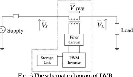
Dynamic Voltage Restorer (DVR) is one of the best methods to address voltage sag problems. DVR is a solid state device which consists of energy storage device and injection transformer that injects the voltage into the system in order to regulate the load side voltage [13]. DVR is connected in the distribution system between the supply and load. The schematic diagram of the DVR is shown in fig.6.
Fig. 6 The schematic diagram of DVR
During the normal operation as there is no sag, DVR will not supply any voltage to the load. When there is a voltage sag in distribution side, DVR will generate a required controlled voltage of high magnitude and desired phase angle which ensures that load voltage is uninterrupted and is maintained.. The difference between the pre sag voltage and the sag voltage is injected by the DVR by supplying the real power from the energy storage element together with the reactive power.
III. SIMULATION RESULTS AND DISCUSSIONS
Fig. 7 Overall block diagram of the proposed system
Fig. 8 PV output voltage waveform The output obtained from the PV array is shown in the fig.8.
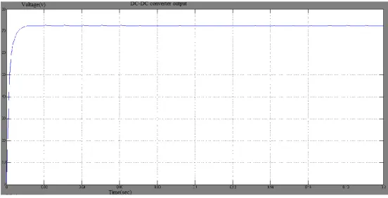
Fig. 9 DC-DC Converter output waveform
Fig. 10 Multilevel inverter output waveform The Multilevel inverter output is shown in the fig.10.
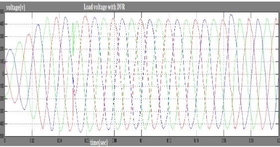
Fig. 11 Load voltage without DVR waveform
On the occurrence of fault, the difference between the pre sag voltage and sag voltage is injected by the DVR there by mitigating the voltage hang down. Fig.12 shows the load voltage on interfacing with DVR
IV. CONCLUSION
In this work, the voltage in the distribution side was regulated when the disturbance occurs in the load feeder by means of DVR which has excellent compensation for voltage disturbances. Simulation was carried out with PV interfaced multilevel inverter and DVR using MATLAB/SIMULINK software. The simulation results show that the Fuzzy-DVR is satisfactory in mitigating the Voltage sag.The future scope of the present work is to increase multi level inverter stages to ensure the harmonic free oscillation. We can get the desired results for the non linear load by means of hybrid fuzzy based controller to drive the power switches in the inverter
.
REFERENCES
[1]. Ghosh A. and Ledwich G, ‘Power Quality Enhancement Using Custom Power Devices’, Kluwer Academic Publishers, 2002.
[2]. Ahmed M.Massoud and Shehab Ahmed, ‘Evaluation of Multilevel cascaded type Dynamic Voltage Restorer employing discontinuous space vector modulation’ IEEE Transactions on Industrial electronics, Vol.57,No.7,July 2010.
[3]. Benachaiba Chellali and Ferdi Brahim, ‘Voltage Quality Improvement Using DVR’, Electrical Power quality and Utilization, Journal Vol.14,No.1,2008.
[4]. Adel A.Elbaset, Hamdli Ali and Monstaser Abd El-sattar, ‘ Modified Perturb and Observe MPPT algorithm for Photovoltaic System’, Journal of Engineering sciences, Vol.43,No.3, May 2015
[5]. Dash.P.P and Yazdani, ‘A mathematical model and Performance for a single stage grid connected Photovoltaic (PV) system’, International Journal of Emerging Electric Power Systems, Vol.9, Issue 6.Article 5, 2008.
[6]. Ernesto Ruppert Filho, Jonas Rafael Gazoli and Marcelo Gradella, ‘Comprehensive Approach to Modeling and Simulation of Photovoltaic Arrays’ ,IEEE Transactions on Industrial Electronics, Vol.24,No.5,pp.1198-1208, May 2009.
[7]. Chapman P.L and Esram T, ‘Comparison of photovoltaic array maximum power point tracking techniques’, IEEE Transactions on Energy Conversion, Vol.22,No.2,pp.434-449, June 2007.
[8]. Rajesh Ahuja and Rajesh Kumar, ‘Design and simulation of Fuzzy Logic Controller based Switched Mode Power Supply’, International of Electrical Engineering, Vol.2, Issue 5, May 2014.
[9]. Ritwik Majumder, ‘Reactive power compensation in single phase operation of Microgrid’, IEEE Transactions on Industrial Electronics, Vol.60, No.4, pp.1403-1416, April 2013.
[10].Basim Alsayid and Samer Alsadi, ‘Maximum power point tracking simulation for Photovoltaic system using Perturb and Observe algorithm’ , International Journal of Innovation and Technology’ , Vol.2, Issue.6, December 2012.
[11].Gaurag Sharma and Jay Patel, ‘Modeling and Simulation of solar photovoltaic module using Matlab/Simulink’ , International Journal of Research in Engineering and Technology, Vol.02.Issue.03, March 2013.
[12].Boochiam P and Mithulanathan N, ‘Understanding of Dynamic Voltage Restorers through Matlab’, Thammasat International Jounal of Science and Technology, Vol.11, No.3, September 2006.