An Efficient DCT Computational Algorithm
Suitable for VLSI Implementation
Vijayan .T1, Latha .S 2, Sridhar Raja .D3
Assistant Professor, Dept. of Electronics & Instrumentation Engineering, Bharath University,Chennai,
Tamil Nadu, India1
Professor & Head, Dept. of Electronics & Instrumentation Engineering, Bharath University,Chennai, Tamil
Nadu, India 2
Assistant Professor, Dept. of Electronics & Instrumentation Engineering, Bharath University,Chennai,
Tamil Nadu, India 3
*Corresponding Author,
ABSTRACT: This paper proposes an efficient Discrete Cosine Transformation (DCT) computational algorithm by
using a novel coordinate rotation digital computer (CORDIC)- based fast radix-2 algorithm. It has some distinguish advantages, such as Coolwey-Tukey Fast Fourier Transformation (FFT) like regular data flow, uniform post-scaling factor, in-place computation and arithmetic sequence rotation angles. Compared to existing DCT algorithms the proposed algorithm has lower computational complexity. Furthermore the proposed algorithm is efficient, less complex, reliable and suitable for VLSI implementation
KEYWORDS: Discrete Cosine Transformation, Coordinate Rotation Digital Computer (CORDIC),Coolwey-Tukey
Fast Fourier Transformation.
I. INTRODUCTION
Algorithms in the non radix category attempt to reduce computational complexity and make computations more efficient, such as matrix factorization directly deduced from signal flow graphs , and coordinate rotation digital computer (CORDIC) -based fast algorithms. Due to extensive design optimization for cost reduction and performance enhancement, these DCT algorithms are often complicated and hardly scalable to more than 8-point DCTs.
Compared to non radix algorithms, a radix algorithm allows generating higher-order DCTs from lower-order DCTs. Furthermore, radix algorithms generally have a regular computational structure, which reduces implementation complexity. However, due to their recursive nature, radix algorithms are difficult to realize pipeline and are not suitable for high-speed applications. The project combines both the CORDIC algorithm and radix2 algorithm to reduce the computational complexity and to get efficient results, highly suitable for VLSI implementation since it is built using shifters and adders only. Here the approximation of DCT is computed using binary shift and addition operation only.
II. RADIX ALGORITHM
Since the discrete cosine transformation (DCT) was proposed by Ahmed, various fast algorithms have been
Due to extensive design optimization for cost reduction and performance enhancement, these DCT algorithms are often complicated and hardly scalable to more than 8-point DCTs. Compared to non radix algorithms, radix algorithms allow us to generate higher-order DCTs from lower-order DCTs. Furthermore, radix algorithms generally have a regular computational structure, which reduces implementation complexity. However, due to their recursive nature, radix algorithms are difficult to realize pipeline and are not suitable for high-speed applications. Among radix algorithms, the radix-2 algorithm is the most popular because of its computational efficiency and structural simplicity. Based on the proposed algorithm, signal flows of DCTs and inverse DCTs (IDCTs) are developed and deduced using their orthogonal properties, respectively [2].
III. CORDIC ALGORITHM
As the name suggests the CORDIC algorithm was developed for rotating coordinates, a piece of hardware for doing real-time navigational computations in the 1950's. The CORDIC uses a sequence like successive approximation to reach its results. The nice part is it does this by adding/subtracting and shifting only. Suppose we want to rotate a point(X,Y) by an angle(Z) [3].
The coordinates for the new point (Xnew, Ynew) are
Xnew = X * cos(Z) - Y * sin(Z) Ynew = Y * cos(Z) + X * sin(Z) or rewritten:
Xnew / cos(Z) = X - Y * tan(Z) Ynew / cos(Z) = Y + X * tan(Z)
It is possible to break the angle into small pieces, such that the tangents of these pieces are always a power of 2.
This results in the following equations: X(n+1) = P(n) * ( X(n) - Y(n) / 2^n) Y(n+1) = P(n) * ( Y(n) + X(n) / 2^n) Z(n) = atan(1/2^n)
The a tan(1/2^n) has to be pre-computed, because the algorithm uses it to approximate the angle. The P(n) factor can be eliminated from the equations by pre-computing its final result. If we multiply all P(n)'s together we get the aggregate constant.
P=cos(atan(1/2^0))*cos(atan(1/2^1))*cos(atan(1/2^2))... cos(atan(1/2^n))
This is a constant which reaches 0.607... depending on the number of iterations and the number of bits used. The final equations look like this:
Xnew = 0.607... * Sum(X (n) - Y (n) / 2^n) Ynew = 0.607... * Sum(Y (n) + X (n) /2^n)
Now it is clear how we can simply implement this algorithm, it only uses shifts and adds/subs. Or in a program-like style:
For i=0 to n-1 if (Z(n) >= 0) then
X(n + 1) := X(n) – (Yn/2^n); Y(n + 1) := Y(n) + (Xn/2^n); Z(n + 1) := Z(n) – atan(1/2^i); else
Z(n + 1) := Z(n) + atan(1/2^i); end if;
end for;
Where 'n' represents the number of iterations.
IV. DCT BLOCK
A discrete cosine transform (DCT) expresses a finite sequence of data points in terms of a sum of cosine
functions oscillating at different frequencies [6]. DCTs are important to numerous applications in science and engineering, from lossy compression of audio (e.g. MP3) and images (e.g. JPEG) (where small high-frequency components can be discarded), to spectral methods for the numerical solution of partial differential equations. The use of cosine rather than sine functions is critical in these applications: for compression, it turns out that cosine functions are much more efficient (as described below, fewer functions are needed to approximate a typical signal), whereas for differential equations the cosines express a particular choice of boundary conditions [4].
In particular, a DCT is a Fourier-related transform similar to the discrete Fourier transform (DFT), but using only real numbers. DCTs are equivalent to DFTs of roughly twice the length, operating on real data with even symmetry (since the Fourier transform of a real and even function is real and even), where in some variants the input and/or output data are shifted by half a sample. There are eight standard DCT variants, of which four are common.
The most common variant of discrete cosine transform is the type-II DCT, which is often called simply "the DCT, its inverse, the type-III DCT, is correspondingly often called simply "the inverse DCT" or "the IDCT". Two related transforms are the discrete sine transforms (DST), which is equivalent to a DFT of real and odd functions, and the modified discrete cosine transforms (MDCT), which is based on a DCT of overlapping data [5].
V. CORDIC BASED FAST DCT ALGORITHM
For an N-point signal as shown in fig 2.1, the DCT is defined as,
(1)
Where α [0] =1/ N if k = 0, and α [k] = 2/ N otherwise
According to(1), neglecting the post-scaling factor without loss of generality, the main operation of an N – point DCT denoted as DCT can be written as,
(2)
where k=0,1,2,….,N-1.
A length N input sequence x[n], with N is power-of-two, can be decomposed intoxL[n] and xH[n], which are defined as: xL[n]=1/2{x[2n]+x[2n+1]}and (3)
xH[n] =1/2{x[2n]-x[2n+1]}; (4) where n=0, 1, 2,……, (N/2)-1.
So the original signal[n], can be obtained from xL[n] and xH[n] as follows:
x[2n]=xL[n]+xH[n] (5) x[2n+1]=xL[n]-xH[n] (6)
+
(7)
Where k=0,….,N-1 Since
(8)
We get (9) and (10)
(9)
(10) Where k=0… N/2-1
From (9) and (10), we find that each equation has two N/2-point DCT with two different coefficients, and the four coefficients just make one CORDIC. Hence, we combine the two equations to realize a CORDIC based fast DCT algorithm [7-10].
Fig.2.1 Signal flow of an n-point fast discrete cosine transformation
Fig.2.3 Signal flow of a 4-point fast discrete cosine transformation (DCT).
Fig.2.4Signal flow of a 8-point fast discrete cosine transformation (DCT).
Let
Combining the constant values 2 and √2 in recursively decomposing stages with the post-scaling factor, the DCT can be written as:
The above diagram (fig 2.4) equation
Application
CORDIC uses simple shift-add operations for several computing tasks such as the calculation of trigonometric, hyperbolic and logarithmic functions, real and complex multiplications, division, square-root calculation, solution of linear systems, eigen value estimation, singular value decomposition, QR factorization and many others [11]. As a consequence, CORDIC has been utilized for applications in diverse areas such as signal and image processing, communication systems, robotics and 3-D graphics apart from general scientific and technical computation.
DCT and IDCT signal flow based on proposed algorithm
The general signal-flow graph for the proposed fast DCT algorithm given while the signal-flow graphs of 2-point DCT, 4-point DCT, and 8-point DCT are respectively represented where the angles in the circles are used to represent CORDICs with this rotation angles.
There are two separate -point DCTs and one CORDIC array. As mentioned above, the CORDIC array has CORDICs with arithmetic-sequence rotation angles [12]. The inputs are addressed in bit-reverse order and the outputs are addressed in natural order. It also supports in-place computation like the FFT. Regular and pure feed-forward data paths of the signal flow make them suitable for pipelined VLSI implementation. For special applications, a double-angle formula can be used to reduce CORDIC types. Hence, the architecture based on the signal flow is highly modular. Furthermore, the modified unfolded CORDIC, which presented in our previous work, can be used to speed up computations and overcome recursive problems in conventional CORDICs [13].
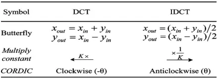
and the signal flow of the -point IDCT can be easily obtained by inverting the transfer function of each building block shown in Table 2.1 and reversing the signal flow direction.
Table 2.1 transfer function of DCT and IDCT
The CORDICs in the DCT and IDCT have the same rotation angle but opposite rotation directions. When changing the CORDIC from a clockwise to an anticlockwise rotation with the same angle, the only thing that is required is to change all adders to subtractors and subtractors to adders in the rotation iteration stage. This results in an easy way to implement a reconfigurable or unified architecture for DCTs and IDCTs. Notice that the proposed fast IDCT algorithm has the same arithmetic complexity as does the DCT.
VI. FEATURES OF PROPOSED CORDIC-BASED FAST DCT ALGORITHM.
Hardware complexity:
The CORDIC-based algorithm is highly suitable for VLSI implementation, since it is built using shifters and adders only. Liang et al. [7] propose lifting scheme-based fast multiplierless approximation of the DCT using only binary shift and addition operations. This results in a very low hardware complexity VLSI implementation. We use the modified unfolded CORDIC to realize a low hardware complexity VLSI implementation also using only binary shift and addition operations. Moreover, the computational accuracy can be selected based on the trade-off between the hardware complexity and approximation error. In addition, since our proposed algorithm has uniform post-scaling factor, it is also suitable for scaled DCT implementation. The block diagram and the corresponding layout view of the proposed 8-point DCT after placement and routing based on SMIC 0.18 standard cell library. This design (excluding the I/O pads) has area of 627738 with power consumption of 12.5 mW under operating frequency of 66.7 MHz.
Scalability:
Many CORDIC-based algorithms are limit to short-length DCT, such as the algorithms based on Loeffler’s DCT. Our proposed algorithm provides much easier and more regular way to realize the scalability, which can be easily extended to compute long-length DCTs as long as the transform length is power-of-two.
Modularity:
For -point DCT, our proposed algorithm requires CORDICs with only different CORDIC types. Furthermore, the rotation angles of the CORDICs in our proposed algorithm are arithmetic-sequence, the double-angle formula can be used to reduce the number of the CORDIC types and make this algorithm highly modular. Compared to the CORDIC-based architectures, our architecture has better modularity.
Pipelinability:
The architectures is recursive in nature, thus making them difficult to realize pipeline. We use the modified unfolding CORDIC to overcome this problem. Moreover, the regular and purely feed forward data path makes our proposed algorithm based architecture suitable for pipelined VLSI implementation [14].
Reconfigurability:
VII.FAST DCT ALGORITHM
Forward DCT
The DCT of a sequence {x[m], (m=0,…..N-1)} can be implemented by FFT. First we define a new sequence:{y[m], (m=0,…..N-1)}
Then the DCT of x[n] can be written as the following (the coefficient a[n] is dropped for now for simplicity):
where the first summation is for all even terms and second all odd terms. We define for the second summation, then the limits of the summation 0 and N/2-1 for m becomes N-1 and N/2 form m’, and the second summation can be written as
Now the two summations in the expression of x[n] can be combined
Next, consider the DFT of y[m]:
If we multiply both sides by
and take the real part of the result (and keep in mind that both x[m] and y[m] are real), we get:
This expression for is identical to that for X[n] above, therefore we get
where Y[n] is the DFT of y[m] (defined from x[m]) which can be computed using FFT algorithm with time complexity
O(Nlog2N).
In summary, fast forward DCT can be implemented in 3 steps:
Step 1: Generate a sequence y[m] from the given sequence x[m]:
step 2: Obtain DFT Y[n] of y[m] using FFT. (As y[m] is real, Y[n] is symmetric and only half of the data
points need be computed.) Y[n] = F[y[m]]
step 3: Obtain DCT X[n] from Y[n] by
Inverse DCT
The most obvious way to do inverse DCT is to reverse the order and the mathematical operations of the three steps for the forward DCT:
step 1: Obtain Y[n] from X[n]. In step 3 above there are N equations but 2N variables (both real and
imaginary parts of Y[n]). However, note that as y[m]’s are real, the real part of its spectrum Y[n] is even (N+1 independent variables) and imaginary part odd (N-1 independent variables). So there are only N variables which can be obtained by solving the N equations.
step 2: Obtain y[m] from Y[n] by inverse DFT also using FFT in N log 2 N complexity.
y[m] = F-1[Y[n]]
Step 3: Obtain x[m] from y[m] by
However, there is a more efficient way to do the inverse DCT. Consider first the real part of the inverse DFT of the sequence: X[n]
This equation gives the inverse DCT of all N/2 even data points x (2m)
(m = 0… N/2-1). To obtain the odd data points, recall that x[m ]= x[2N-m-1], and all odd data points
can be obtained from the second half of the previous equation in reverse order
(m = N-1,N-2,…,N/2).
In summary, we have these steps to compute IDCT:
The mathematically equivalent to the steps of the first method
Y[n] =X[n]
Step 2: Obtain y[m] from Y[n] by inverse DFT also using FFT. (Only the real part need be computed.)
Step 3: Obtain x[m]’s from y[m]’s by
VIII. IMPLEMENTATION CONSIDERATION AND COMPARISONS
The -point proposed DCT algorithm needs two–point DCTs, CORDICs, and additions. Therefore, the number of CORDICs required by the proposed algorithm is
C(N)=
and the number of additions is A(N) = N log2N
IX. RESULT AND ANALYSIS
The proposed algorithm can generate the next higher-order DCT from two identical lower-orders DCTs.
After simulation the result of 2-point DCT and 4-point DCT are shown in fig4.1 and fig 4.2.
CORDIC-based fast radix-2 DCT algorithm requires N log2N additions and N/2log2N –N+1 CORDICs.
Fig 4.1 simulation of 2-point DCT
X. CONCLUSION
A novel CORDIC-based radix-2 fast DCT algorithm was proposed. This algorithm can generate the next higher order DCT from two identical lower-order DCTs. Compared to existing DCT algorithms, our proposed algorithm has several distinct advantages, such as low computational complexity, and being highly scalable, modular, regular, and able to admit efficient pipelined implementation.
REFERENCES
1. Hai Huang and Liyi Xiao, Member, IEEE “CORDIC Based Fast Radix-2 DCT Algorithm” IEEE SIGNAL PROCESSING LETTERS, VOL.
20, NO. 5, MAY 2013
2. Das M.P., Jeyanthi Rebecca L., Sharmila S., "Evaluation of antibacterial and antifungal efficacy of Wedelia chinensis leaf extracts", Journal of
Chemical and Pharmaceutical Research, ISSN : 0975 – 7384, 5(2) (2013) pp.265-269.
3. N. Ahmed, T. Natarajan, and K. R. Rao, “Discrete cosine transform,” IEEE Trans. Comput., vol. C-23, pp. 90–94, 1974.
4. T. D. Tran, “The binDCT: Fast multiplier less approximation of the DCT,” IEEE Signal Process. Lett., vol. 7, no. 6, pp. 141–144, 2000.
5. Subhashini V., Ponnusamy S., Muthamizhchelvan C., "Growth and characterization of novel organic optical crystal: Anilinium d-tartrate
(ADT)", Spectrochimica Acta - Part A: Molecular and Biomolecular Spectroscopy, ISSN : 1386-1425, 87() (2012) pp.265-272.
6. W. H. Chen, C. H. Smith, and S. C. Fralick, “A fast computational algorithm for the discrete cosine transform,” IEEE Trans. Commun., vol. 25,
no. COM-9, pp. 1004–1009, Sep. 1977.
7. Thomas J., Ragavi B.S., Raneesha P.K., Ahmed N.A., Cynthia S., Manoharan D., Manoharan R., "Hallermann-Streiff syndrome", Indian
Journal of Dermatology, ISSN : 0019-5154, 58(5) (2013) pp.383-384.
8. E. Feig and S.Winograd, “Fast algorithms for the discrete cosine transform,” IEEE Trans. Signal Process., vol. 40, no. 9, pp. 2174–2193, Sep.
1992.
9. V. Britanak and K. R. Rao, “Two-dimensional DCT/DST universal computational structure for block sizes ,” IEEE Trans. SignalProcess., vol.
45, no. 11, pp. 3250–3255, Nov. 2000.
10. Subha Palaneeswari M., Ganesh M., Karthikeyan T., Manjula Devi A.J., Mythili S.V., "Hepcidin-minireview", Journal of Clinical and Diagnostic Research, ISSN : 0973 - 709X, 7(8) (2013) pp.1767-1771.
11. C. Loeffler, A. Ligtenberg, and G. Moschytz, “Practical fast 1-D DCT algorithms with 11 multiplications,” in Proc. Int. Conf. Acoust.,Speech,
Signal Process., 1989, pp. 988–991.
12. Laljee R.P., Muddaiah S., Salagundi B., Cariappa P.M., Indra A.S., Sanjay V., Ramanathan A., "Interferon stimulated gene - ISG15 is a potential diagnostic biomarker in oral squamous cell carcinomas", Asian Pacific Journal of Cancer Prevention, ISSN : 1513-7368, 14(2) (2013) pp.1147-1150.
13. J. Liang and T. D. Tran, “Fast multiplier less approximations of the DCT with the lifting scheme,” IEEE Trans. Signal Process., vol. 49, no. 12,
pp. 3032–3044, 2001.
14. Pandimadevi V., Kujambal A., Sudhakar S., Ramaiah B., Gupta S., Srinivasan K.S.V., "Upgrading low-grade grain leather using high
performance polymeric dispersions by a transfer coating system", Journal of the American Leather Chemists Association, ISSN : 0002-9726, 96(5) (2001) pp.157-161.
15. T.Nalini ,A.Gayathri,HVS Based Enhanced Medical Image Fusion ,International Journal of Innovative Research in Computer and
Communication Engineering,ISSN (Print) : 2320 – 9798 , pp 170-173, Vol. 1, Issue 2, April 2013.
16. S.Thirunavukkarasu, r.K.P.Kaliyamurthie ,EFFICIENT ALLOCATION OF DYNAMICRESOURCES IN A CLOUD,International Journal of
Innovative Research in Computer and Communication Engineering, ISSN: 2249-2651, pp 24-29,Volume1 Issue3 Number2–Dec2011.
17. K.G.S. VENKATESAN,Planning in FARS by dynamic multipath Reconfiguration system failure recovery in Wireless Mesh
Network,International Journal of Innovative Research in Computer and Communication Engineering,ISSN(Online): 2320-9801,pp 5304-5312,Vol. 2, Issue 8, August 2014.
18. G.Michael, An Empirical Approach – Distributed Mobility Management for Target Tracking in MANETs ,International Journal of Innovative
Research in Computer and Communication Engineering , ISSN (Print) : 2320 – 9798 , pp 789-794 , Vol. 1, Issue 4, June 2013.
19. G.AYYAPAN , Malicious Packet Loss during Routing Misbehavior - Identification, International Journal of Innovative Research in Computer