SIMULATION OF SPREAD SPECTRUM RADAR USING RAKE AT THE RECEIVER END
D. Kandar
Sikkim Manipal Institute of Technology Sikkim Manipal University
Majitar, Sikkim 737136, India C. K. Sarkar
Department of Electronics and Telecommunication Engineering Jadavpur University
Kolkata 700032, India R. Bera
Sikkim Manipal Institute of Technology Sikkim Manipal University
Majitar, Sikkim 737136, India
Abstract—Intelligent Transport Systems (ITS) are becoming a reality, driven by navigation safety requirements and by the investments of car manufacturers and Public Transport Authorities all around the world. ITS make it possible to imagine a future in which cars will be able to foresee and avoid collisions, navigate the quickest route to their destination, making use of up-to-the minute traffic reports, identify the nearest available parking slot and minimize their carbon emissions. Also demand for voice, data and multimedia services, while moving in car increase the importance of broadband wireless systems [1]. Efforts are being imparted towards the convergence of mobile communications, computing and remote sensing. Spread spectrum based digital RADAR can be utilized as a remote sensing device in ITS. This motivates us in development of DSSS (Direct Sequence Spread Spectrum) based digital RADAR at our institute. It is quite capable of detecting target in the open field. The experiment was carried out for different standard target like flat plates, spheres etc. The operational digital RADAR is capable of
rejecting interference, but fails in a strong multipath scenario. Again RAKE processing is established in communication. Our approach is implementing RAKE processing at the RADAR receiver to exploit multipath.
1. INTRODUCTION
RADAR technology has been investigated for use on automobiles since the 1970s and has been employed for various functions on automobiles since the early 1980s [2, 3]. Initial usage of microwave RADAR was for collision warning applications on commercial vehicles, such as ambulances, buses, and trucks. The advantage of RADAR sensors, is that they perform equally well during the day, the night, and in most weather conditions. RADAR can also be used for target identification and for detecting road conditions by making use of scattering signature information. Most likely the RADAR sensors will be an integral part of any multiple sensor system, or sensor fusion, used to achieve a true autonomous vehicle.
Multipath environments and electromagnetic interference are very common in RADAR measurement set-up and give rise to severe problem in accuracy of measurement [4]. The challenges for conventional outdoor target detection in the low frequency region of RADAR operation the problems of clutter, multipath & interference are more severe [5]. A targets RCS represents the amount of energy reflected from the target toward the receiver as a function of the target aspect with respect to the transmitter receiver pair. It is well known that this function is rapidly changing as a function of the target aspect [6]. Some latest technological methods like DSSS, OFDM (Orthogonal Frequency Division Multiplexing), MIMO (input multiple-output) can be utilized in the open range measurement set-up [7, 8]. 1.1. Spread Spectrum RADAR and Its Advances over Conventional RADAR
The baseband signal d(t), having bit rate of fb(= 1/Tb), is first modulated in PSK modulator. The modulated signal is defined as
s(t) =√2P sd(t) cosωt,
where ω is the carrier frequency and P s is the corresponding power. Now this signal is spreaded (modulated again) by pseudonoise (PN) signal having chip rate fc(= 1/Tc). The spread spectrum signal is given by
This signal now can be upconverted and transmitted. At the receiver end the signal can be downconverted, de-spreaded and demodulated. The de-spreading is done through correlation process. Autocorrelation,
Ra(τ), is defined by the integral
Ra(τ) =
f(t)f(t−τ)dt
It is a measure of a similarity between a signal f(t) and time sifted replica of itself. Cross-correlation Rc(τ), is defined as the correlation between two different signals f(t) andg(t) and is defined by
Rc(τ) =
f(t)g(t−τ)dt
Spread spectrum communication systems employ waveform similar to those of pulse compression RADAR. The purpose of such waveform in communication is to allow multiple simultaneous use of the same frequency spectrum.
Patented RADAR technologies are now available that has major advantages eliminating the most of the disadvantages of either pulse or continuous wave approaches. Those are based on the use of a digital pseudo-random binary code, similar to the spread spectrum technology in wireless mobile communications. The technology uses DSSS signals to create noise like modulation, making the transmitted signal virtually undetectable. Spread spectrum radio has long been used in military communications because of this advantage [9]. Thus the waveform of choice will be phase coded pulse compression using digital techniques instead of Linear Frequency Modulation (LFM) based analog techniques. Sometimes pulse compression RADARs have been called spread spectrum RADARs [10, 11]. The pulse compression nature of this signal processing provides significant protection against normal Interference. Therefore, a DSSS RADAR will be aimed for the development.
The design & development of Instrumentation RADAR at the low frequency band should be aimed for the following additional benefits:
i) Local suppression of interference due to coded RADAR waveform and correlation of the received code.
ii) High level of multipath rejection
iii) Higher reliability/efficiency and low power consumption due to coding of the baseband pulses.
chosen to be either 0 orπ radian. If the selection of the 0, π phase is made at random, the waveform approximates a noise modulated signal with a thumbtack ambiguity function, the output of the matched filter will be a spike of widthwwith an amplitude N times greater than that of the long pulse. The pulse compression ratio is N = T /w = BT, whereB = 1/w. The output waveform extends a distance T to either side of the peak response, or central spike. The portions of the output waveform other than the spike is called the time sidelobes.
2. HARDWARE SET-UP OF OPERATIONAL DSSS RADAR
A DSSS bi-static RADAR transmitter made up of WiFi b PCI adapter fitted inside a PC with a horn antenna as shown in Fig. 1 is operational at SMIT using 2.4 GHz radio carrier [12]. The block diagram of such RADAR is shown in Fig. 2. The RADAR setup was conducted in a bi-static mode and the position of two dish antennas is placed side by side with a distance of 15 ft. A transmitting horn is connected to WiFi b adapter fitted inside a PC after removal of the helical omni
Figure 1. DSSS RADAR system.
Software for Measurement of Signal Strength
Spreading
RF Transmitter
Scrambling DeSpreading RF
Receiver DeScrambling
Software for Measurement of Signal Strength
Target
directional antenna. The radio wave is finally radiated through a dish antenna of diameter 6 ft with the transmitting horn at its focus. At the receiver another USB WiFi b adapter is connected to a second horn with another dish. The receiving dish antenna was kept at an angle of 17.5 degrees and the transmitting dish antenna was kept at an angle of 3.37 degrees from the reference angle and the receiving horn antenna was kept at a height of 5 feet 7 inches and the transmitting horn antenna was kept at a height of 4 feet 6 inches. To avoid direct coupling between two dish antennas, the horn antennas were aligned at the offset position of the dish antennas and the WiFi cards were covered by the metallic boxes to avoid direct leakage.
The system is able to detect the nearby targets like a person, tree leaves, thin rod etc. The RADAR is also able to differentiate different flat plates of different cross sections, different spherical objects having different radii. The DSSS RADAR so developed can be very much useful for open field target detection. This motivates us at SMIT to extend the experiment further.
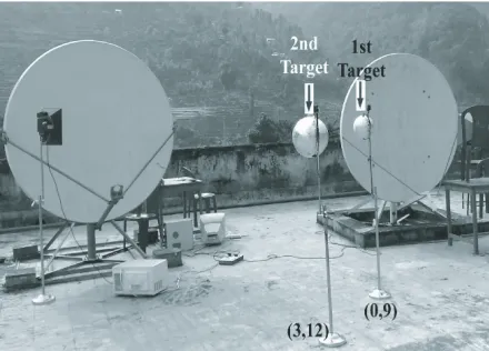
3. FIELD STUDY OF ENVIRONMENTAL EFFECTS
The digital RADAR is working fine in the open field. We extended the experiment to measure it’s performance in a multipath environment. Artificially we created the multipath environment by putting multiple targets on the operational zone of the roof top. We putted different number of target at different position as shown in the Fig. 3. The signal strength varies with the number of scatterers. The variation of signal strength with different number of scatterers are shown in the Table 1. The Signal strength was additive or subtractive depending on the positions of the scatterers.
The additive or subtractive nature of signal strength is due to multipath signals. Multipath signals act as same or other phases (may be opposite) which is reducing the main signal.
Table 1. Different signal strength for multipath effect.
Coordinates of Desired
Target (ft)
Signal strength of single object (ft)
Coordinates of second
object (ft)
Combined signal strength
(dBm)
Remarks
0.9 −63 3.12 −58 Additive
−3.6 −59 3.12 −57 Additive
−3.6 −59 0.9 −64 Subtractive
0.9 −63 −3.6 −54 Additive
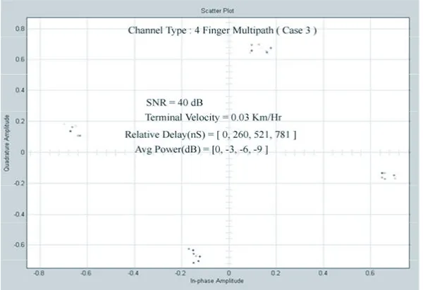
4. MATLAB SIMULATION OF DIGITAL RADAR
The SS technology is well known for its antijamming and security features [13–20] in communication system. The conventional Wi-Fi ‘b’ system based on SS technology is capable of resolving the problem of interference but it has no solution to the undesired multi-path effect caused due to the presence of multiple scatterers in the environment. So, the inspiration behind implementing RAKE receiver is to exploit these multi-paths in a positive manner so as to construct a signal of greater strength which matches the transmitted signal in all aspects. RAKE receiver is well established in WCDMA [21]. The block diagram of the RAKE receiver is shown in the Fig. 4. The different fingers of the arriving signals are treated at different correlators. The correlator first de-spreads the incoming signal with a factor equal to that by
Figure 4. Matlab block of rake receiver.
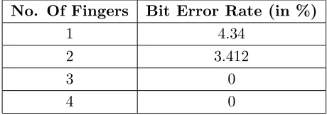
Table 2. BER (%) for different number of fingers. No. Of Fingers Bit Error Rate (in %)
1 4.34
2 3.412
3 0
4 0
which it was spreaded (the PN sequence used for this purpose exactly matches with the PN sequence in the transmitter section). It estimates the channel which gives us the phase and amplitude corrections to be made in the signal. The RAKE receiver has number of correlators (individual correlators take care of the individual multi-paths also called as fingers). The different correlators are time synchronised to extract the valid information out of the different fingers which reach the receiver with some inter-finger delays.
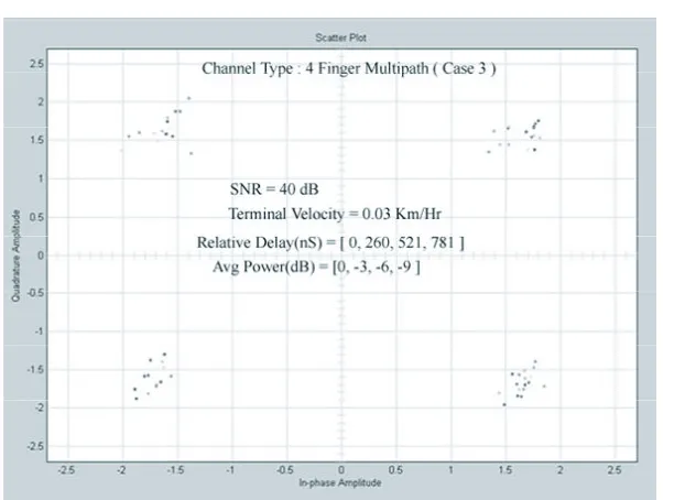
The signals out of each correlator are then combined and the combined signal is normalized with a normalization factor to obtain the desired output signal [12, 22].
Figure 5. Received (Rx signal).
Figure 7. Combined signal.
Table 3. Comparison between different channels. Channel
Type AWGN
Multipath Case 1
Multipath Case 2 Rx area 0.558 0.051 0.9589 Combined area 11.37 10.78 11.05
Fading Depth 3 dB 4.5 dB 7.3 dB Rotation 0 degree 39 degree 35 degree
Number of fingers 1 2 4
Thus limitation of hardware experiment of DSSS RADAR in deferent outdoor condition can be solved with the use of RAKE processing at the receiver of the digital RADAR. Again RAKE processing can be used to combat clutter problem of outdoor RADAR measurement with proper tuning of the RADAR system.
5. CONCLUSION
From our past experience of development of a RADAR system clutter problem in the open field, is more serious and should not be allowed to repeat. The operational DSSS RADAR is able to detect the nearby targets. We have also measured different target parameters. The design & development RADAR at the low frequency band should be aimed for the benefits, like local suppression of Interference due to coded radar waveform and correlation of the received code, high level of multipath rejection and also low power consumption due to coding of the baseband pulses. The hardware experiment was conducted in different environmental as well as different weather condition. In a foggy multipath environment, the RADAR performance was not so good. Software simulation including RAKE processing at the receive end solves the multipath problem and targets have been detected successfully. Thus problem in hardware experiment has been solved in software simulation.
REFERENCES
1. Huang, X., “Smart antennas for intelligent transportation sys-tems,” 6th International Conference on ITS Telecommunications Proceedings, 2006.
2. Belohoubek, E. F., “Radar control for automotive collision mitigation and headway spacing,” IEEE Trans. Veh. Technol., Vol. 31, 89–99, May 1982.
3. Brus, E., “Vehicular radar: The ultimate aid for defensive driving,” Microwaves & RF, 53–58, Sep. 1987.
4. Bera, R., J. Bera, S. Sil, D. Kandar, and D. Dey, “Use of spread spectrum based cellular phone technology to ‘digital radar’,” CODEC 2004, Calcutta University, Kolkata, Jan. 1–3, 2004. 5. Kandar, D. and R. Bera, “Development of an imaging radar
6. Skolnik, M.,Introduction to Radar System, 3rd edition, McGraw-Hill, 2002.
7. Foschini, G. J., “Layered space-time architecture for wireless communication in a fading environment whwn using multielement antennas,”Bell Laboratories Technical Journal, Vol. 1, No. 2, 41– 59, 1996.
8. Hanzo, L., L.-L. Yong, E.-L. Kuan, and K. Yen,Single and Multi-Carrier DS-CDMA Multy-User Detection, Space-Time Spreading Synchronisation and Standards, 1st edition, John Wiley & Sons, 2003.
9. Wolniansky, P. W., G. J. Foschini, G. D. Golden, and R. A. Valenzuela, “V-blast: An architecture for realizing very high data rates over the rich-scattering wireless channel,”Proc. of Issse, 295–300, Pisa, Italy, Sep.–Oct. 1998.
10. Skolnik, M.,Introduction to Radar System, 3rd edition, McGraw-Hill, 2002.
11. Knott, E. F.,Radar Cross Section, 2nd edition, Scitech, Raleigh, NC, 2004.
12. Sinha, N. B., D. Kandar, and R. Bera, “Measurement of target parameters using the dsss radar,” Progress In Electromagnetics Research M, Vol. 1, 185–195, 2008.
13. “Special issue on spread-spectrum communication,”IEEE Trans. Commun., Vol. 30, May 1982.
14. Simon, M. K., et al., “Spread-spectrum communications,” Comp. Sci., Vols. 1–3, 1985.
15. Scholrz, R. A., “Spread-Spectrum Concept,” IEEE Trans. Commun., Vol. 25, Aug. 1977.
16. Torrieri, D. J., Principles of Secure Communication Systems, Artech House, Norwood, MA, 1992.
17. Cooper, G. R. and C. D. McGillem, Modern Communication and Spread-Spectrum, McGraw-Hill, New York, 1986.
18. Glisic, S. G. and P. A. Leppanen (eds.), Code Division Multiple Access Communications, Kluwer Academic, Norwell, MA, 1995. 19. Viterbi, A. J., CDMA Principles of Spread-Spectrum
Communi-cations, Addison-Wesley, MA, 1995.
20. Dixon, R. C.,Spread-Spectrum Systems, John Wiley & Sons, New York, 1984.
21. Heikkil¨a, T., “Rake receiver,” S-72.333 Postgraduate Course in Radio Communications, Dec. 7th, 2004.