Available online:
https://edupediapublications.org/journals/index.php/IJR/
P a g e | 123Fuzzy Controlled Isolated Micro-grid with Battery
Storage and Renewable Energy Sources
Bairi Venkateshwarlu K Nookaraju Koduri Rajender Assistant Professor Assistant Professor M Tech Scholar
Department of EEE Department of EEE Department of EEE
LORDS Inst. of Engg. & Tech, JNTUH L ORDS Inst. of Engg. & Tech, JNTUH LORDS Inst. of Engg. & Tech, JNTUH
Email id: [email protected] Email:[email protected] Email:[email protected] Abstract-The Proposed concep t is imp lement ed t o fuz z y
controlled. The enabling of ac micro grids in dist ribut ion networks allows delivering distributed power and providing grid support services during regular operation of the grid, as well as p owering isolated islands in case of faults and cont ingencies, t hus increasing the performance and reliability of the elect rical system.This project proposes an alternative strategy to cont rol t he generated power wit hin an isolat ed ac microgrid wit h distributed RES. The proposal is to control the terminal volt age of the existing battery banks below or equal it s maximum allowable value. In this particular st udy , t he p ower sy st em consists of a power electronic converter supplied by a bat t ery bank, which is used to form the ac grid (grid former converter), an energy source based on a wind turbine wit h it s resp ect ive p ower electronic converter (grid supplier convert er), and t he p ower consumers (loads). The main objective of this prop osed st rategy is to control the state of charge of t he bat t ery bank limiting the voltage on its terminals by controlling t he p ower generated by the energy sources. This is done wit hout using dump loads or any physical communication among t he p ower electronic converters or the individual energy source controllers. T he electrical frequency of the micro grid is used to inform t he p ower sources and their respective converters about the amount of power that they need to generate in order t o maint ain t he battery-bank charging voltage below or equ al it s maximum allowable limit using mat lab/simulat ion link so ft ware
Index Terms—Battery banks, isolat ed micro grids, p arallel inverters, power control, renewable energy sources (RESs), state of charge (SOC).
I. INTRODUCTION
Micro grids are becoming popular in distribution systems because they can improve the power quality and reliability of power supplies and reduce the environmental impact. Micro grid operation can be classified into two modes: grid-connected and islanded modes. In general, micro grids are comprised of distributed energy resources (DERs) including renewable energy sources, distributed energy storage systems (ESSs), and local loads [1–3]. However, the use of renewable energy sources such as wind and solar power in micro grids causes power flow variations owing to uncertainties in their power outputs.
These variations should be reduced to meet power-quality requirements [4,5]. This study focuses on handling the problems that are introduced by wind power. To compensate for fluctuations in wind power, various ESSs have been implemented in micro grids. Short-term ESSs such as superconducting magnetic energy storage (SMES) systems [6], electrical double-layer capacitors (EDLCs) [7], and flywheel energy storage systems (FESSs) as well as long-term ESSs such as battery energy storage systems (BESSs) [8-9] are applied to micro grid control. ESSs can also be used to control the power flow at point of common coupling in the grid-connected mode as well as to regulate the frequency and voltage of a micro grid in the islanded mode. Among these ESSs, BESSs have been implemented widely owing to their versatility, high energy density, and efficiency. Moreover, their cost has decreased whereas their performance and lifetime has increased.
In practice, BESSs with high performance such as smooth and fast dynamic response during charging and discharging are required for microgrid control. This performance depends on the control performance of the power electronic converter. Proportional-integral (PI) control is a practical and popular control technique for BESS control systems. However, PI control might show unsatisfactory results for nonlinear and discontinuous systems [10].
Available online:
https://edupediapublications.org/journals/index.php/IJR/
P a g e | 124into the larger electrical grid is a new twist on an old
electrical architecture known as the microgrid.
Micro grids are areas of the grid that can operate as part of the larger macro grid or operate autonomously as a standalone system. The micro grid systems help facilitate the integration of DG assets into the larger electrical grid. Further, when properly implemented, micro grids can unlock a wide array of stacked values for grid operators and electrical consumers [12].
II. SYSTEM DESCRIPTION
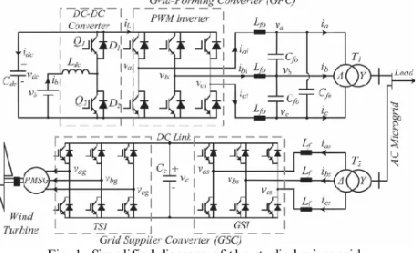
Fig. 1 illustrates the simplified diagram of a stand-alone microgrid used to explain the control strategy proposed in this paper. It consists of a GFC, a GSC, and a battery bank. The renewable energy source, in this particular study, is a variable speed wind turbine coupled to a permanent-magnet synchronous generator (PMSG). Depending on the system size, otherenergy sources and other storage energy systems can be distributed along the microgrid. The simplicity of this system isuseful to show the feasibility of the proposed control strategywithout losing generality.
Fig. 1. Simplified diagram of the studied microgrid.
The GFC is a bidirectional converter formed by a pulse widthmodulation (PWM) three-phase inverter and a dc–dc converterthat works in a buck mode when the battery bank is undercharge or in a boost mode when it is under discharge. The PWMinverter controls the magnitude and frequency of the microgrid
Fig. 2. Block diagram of LC filter implemented in a synchronousreference frame.
Voltage, while the dc–dc buck or boost converter is used tocontrol the voltage at the dc bus capacitor (Cdc) which is thedc bus voltage as well as the charging and discharging of thebattery bank.
The GSC is used to control the power generated by the renewable energy source. In this particular example, the converteris formed by a conventional back-to-back topology [12]. It hasa grid-side PWM inverter (GSI) and a wind turbine-side PWM inverter (TSI). The GSI is used to control the dc-link voltage of the back-to-back topology, and the TSI is used to control the power generated by the wind turbine based on a maximum power point tracker (MPPT) algorithm.
III. GRID FORM ER CONVERTER
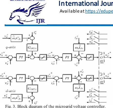
A . Control of the Microgrid Voltage and Frequency The microgrid voltage controller uses the traditional configuration implemented on a synchronous dq reference frame, with an inner current loop and an outer voltage loop [7]. The frequency and voltage reference values are calculated using a droop control strategy as a function of the active and reactive powers, respectively, at the grid former converter terminals. The dq model of the LC filter in the delta side of transformer T1 (see Fig. 1) is used to design the control loops of the GFC. The block diagram of this model is shown in Fig. 3, where Rfo isthe equivalent series resistance of the filter inductor Lfo; ωe is the microgrid frequency in radians per second, the super script’s” denotes variables in the dq synchronous reference frame,ied and ie q are the dq currents in the delta side of transformerT1; Cfy is the per-phase equivalent capacitance of the LC filterand is equal to 3Cfo; and vqe and vde are the dq voltages in thecapacitors of the LC filter. The subscript i denotes the outputvariables of the GFC PWM inverter. All the block diagramsshown in this paper use the operator p = d/dt.Based on the model presented in Fig. 2, an inner current loopand an outer voltage loop were designed, as illustrated in Fig. 3.
Available online:
https://edupediapublications.org/journals/index.php/IJR/
P a g e | 125Fig. 3. Block diagram of the microgrid voltage controller.
Fundamentally, the current on the inductance Lf0 is controlled in order to regulate the voltage on the capacitanceCf0, independently whether the power flux is from the PWMinverter to the microgrid or vice versa.The voltage reference values for the voltage controllers canbe constant, generally equal to the nominal value of the microgrid voltage, or can be calculated based on a droop controlstrategy. In this paper, the voltage reference was fixed in 220 V(rms line voltage in the delta side of T1).
B. Control of the Bidirectional DC– DC Converter The dc–dc converter (in GFC) is used to control the voltage in the capacitor Cdc. The action of the controller of thedc–dc converter can be considered equivalent to connecting acontrolled voltage source, with mean value Vct, between the xyterminals of the converter circuit, as shown in Fig. 4(a) and (b).If the losses in the converter are not considered, the voltage onCdc depends only on the difference between the power at thebattery bank terminals (Pb) and (Pinv) which is the power atthe terminals of the delta side of the isolation transformer T1,which is positive when the power flux is from the inverter to thegrid and negative on the contrary. This is shown in Fig. 4(c).Therefore, the dynamic equation for vdc can be written as in(1), where wdc is an auxiliary variable defined by wdc = v2dc
(1) From (1) and Fig. 4, the dc bus voltage controller of theGFC can be designed with an inner current loop to control thebattery bank current (ib) and an outer voltage loop to controlthe voltage over the capacitor Cdc, as illustrated in Fig. 6.
Fig. 4. DC–DC converter average model: (a) Original circuit, (b) equivalent average circuit of inductor and battery bank, and (c) average
modelof the bus dc.
Fig. 5. Block diagram of the voltage controller of the dc–dc converter.
Fig. 6. Block diagram of the commands for the switches of the dc– dcconverter.
GDID2 is used to decouple the power disturbance from theoutput of the inverter over the dc bus voltage.The output of the voltage controller (Vct) is the referencevalue for the PWM block used to generate the control signal forQ1 or Q2 switches, as shown in Fig. 6 [4].In Fig. 6, when Pinv is positive, the battery bank supplies theload, and the dc–dc converter functions on the boost mode usingthe Q2 switch and D1 diode. On the other hand, when Pinv isnegative, the dc–dc converter functions on the buck mode usingthe Q1 switch and D2 diode.
IV. GRID SUPPLIER CONVERTER
A . Control of the Injected Current in the Microgrid andthe Voltage at the DC Bus
Available online:
https://edupediapublications.org/journals/index.php/IJR/
P a g e | 126Thiscontroller uses an inner current loop to control the
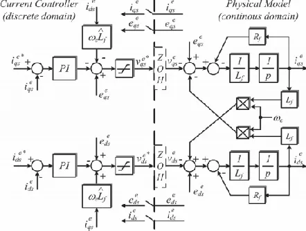
injectedcurrent in the microgrid.The current controller is implemented in a dq synchronousreference frame aligned with the microgrid positive sequencevoltage vector. The converter variable synchronization is doneby using a synchronous phase-locked loop (PLL) that has asecond-order resonant filter tuned for the fundamental frequency of the microgrid.
Fig. 7. Block diagram of the control of the injected current in themicrogrid by the GSC.
Fig. 8. Block diagram of the dc bus voltage controller for the GSC.
This PLL also has a module toextract the instantaneous positive and negative symmetricalcomponents of the voltage of the microgrid [13]. The PLL wastuned based on its small signal analysis model for a bandwidthof 100 Hz. The block diagram of the current controller togetherwith the filter (Lf) model in a synchronous reference frameis illustrated in Fig. 8, where Rf is the equivalent seriesresistance of the inductor Lf, ie qs and ie ds are the currents inthe delta side of transformer T2, and eeqs and eeds are the dqaxis components of the microgrid voltage. The adopted currentdirection references are the same as those shown in Fig. 1.If the losses in the GSI and in the inductor Lf are neglected,the variation of the energy stored in the capacitor Cc is equalto the difference between the active power received from themicrogrid (Ps)
and the active power generated by the windturbine (Pg). Using the convention of Fig. 2, this can beexpressed as in
(2) For a dq synchronous reference frame aligned with themicrogrid voltage vector, it follows that ee ds = 0. Therefore,Psis equal to (3/2) Esie qs, with Es being the magnitude ofthe phase voltage, considered constant in this application. Bydefining Kc equal to (3/2Es), the dynamic equation for thecapacitor Cc is presented in
(3) The block diagram for the dc bus voltage controller is illustrated in Fig. 8. GDID3 is the transfer function used to decoupleat the sample instants the effect of the disturbances due to Pg,and τf is the time constant Lf /Rf. The output of the voltagecontroller is the reference current (ie qs ∗) for the inner currentloop.
V. PROPOSED STRA TEGY TO CONTROL THEGENERA TED POW ER IN THE M ICROGRID
In stand-alone and distributed renewable energy systems, there is no commercial or conventional grid to absorb anysurplus power generated internally in the microgrid. Therefore,the generated power needs to be controlled when the load poweris less than the amount of power that could be generated by theenergy sources. This is necessary to keep the energy balance inthe microgrid under control and to keep the battery bank voltagebelow or equal its maximum allowable value. This is necessarysince voltages higher than the gasification voltage can decreasethe life span of batteries or even damage them irreversibly [17].In the proposed control strategy, the GFC verifies the batterybank voltage to know if it reached the maximum allowedcharging voltage and, if so, change the microgrid frequency toinform the other sources that they must reduce their generatedpower. Based on the microgrid frequency, the control systemsof the power generation sources connected to the microgriddecide whether to restrict the power generated by each of them.
Available online:
https://edupediapublications.org/journals/index.php/IJR/
P a g e | 127ofpower that can be generated, and the existing renewable
energysources can function on their maximum power point. Obviously, this is true only if the battery bank has been designed withsufficient capacity to absorb all the power that the renewablesources can produce at a given instant
On the other hand, if the maximum voltage of the batterybank is reached, the microgrid frequency is imposed to bealways higher than the value fmax, which is the maximum frequency of operation of the conventional droop control strategy.This is illustrated by the hatched area in Fig.9. Now, the valueof the frequency (f) is a variable that changes dynamically
Fig. 9. Frequency versus power in the GFC based on the proposedpower control.
Fig. 10. Block diagram of the frequency control at the GFC.
With the terminal voltage of the battery bank (vb), the powergenerated internally in the microgrid (Pg), and the power of theGFC (Pinv). This can be expressed by (9). As the calculationof the frequency depends on the dynamics of the battery bankvoltage controller, its relationship with the power (Pinv) doesnot follow a well-defined algebraic equation as, for example, astraight line. Therefore, Fig. 3 shows only an illustration thatthe frequency can assume any value between fmax and fmax +Δfmax. In this operating condition, it is necessary to restrict theamount
of power that can be generated by renewable sources;otherwise, the integrity of the battery bank is at risk. Theamount of power that needs to be reduced from the maximumpower that each source is able to produce at every moment hasa direct relation to the frequency difference Δf = f − fmax.The values of fo and ±Δfmax adopted in this work are 60 Hzand ± 0.60 Hz so that the frequency range of the microgrid isbetween 59.4 Hz (fmin) and 61.2 Hz (fmax + Δfmax).
A . Implementation of the Proposed Strategy in the GFC The control of the battery bank voltage, in order to ensureits integrity, was implemented as shown in Fig. 10. While theoutput of the hysteresis loop is zero, the value of the frequencyreference is fe ∗ = f1. On the other hand, while the output of thehysteresis loop is one, a proportional and integral (PI) controlleris used to regulate the terminal voltage of the battery bank equalor below its maximu m allowed value (Vbmax). The output of
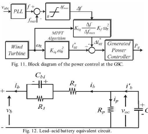
Fig. 11. Block diagram of the power control at the GSC.
Fig. 12. Lead–acid battery equivalent circuit.
This controller is the increment of frequency (Δf) that must beadded to the value fmax to form the new microgrid frequencyreference value (fe ∗ = f2 = fmax + Δf). The value of Δf is proportional to the amount of power that must be decrementedfrom the generated power in order to control the battery bankterminal voltage. The low-pass filter with a 1-Hz bandwidthshown in Fig. 9 is used to avoid sudden variations in frequencydue the hysteresis loop.
Available online:
https://edupediapublications.org/journals/index.php/IJR/
P a g e | 128The grid frequency is measured by the GSC and if its
value ishigher than fmax, it means that the voltage of the battery bank ishigher than its maximum allowed value. For the particular casewhere the renewable energy source is a wind turbine, the GSCpower controller decrements the current reference i∗ q, originallycalculated by (7), which is now calculated by (10), where Kfis a constant which serves to match the rated power of the GFCwith the rated power of the wind turbine. The block diagram ofthis control action is presented in Fig. 11.
As the reference current is now determined by (10), the operating points of the wind turbine-generator set follow the dashedcurve indicated by Tg in Fig. 8. This implies a reduction inthe generator torque, which causes a reduction in power thatis produced by the wind turbine keeping regulated the terminalvoltage of the battery bank.
C. Tuning of the Battery Bank TerminalVoltage Controller
The tuning of the PI controller shown in Fig. 10 takes intoaccount the dynamic of the battery bank. One possible modelfor lead–acid batteries is shown in Fig. 12. In this figure,voc is the battery open circuit voltage, Rs is the equivalentseries internal resistance, R1 and Cb1 are used to model theover- or under voltage that happens when the battery is chargingor discharging, Rp is the resistance due the natural losses, andCbo models the battery capacity to storage energy. Normally,the natural losses occur very slowly, so the effect of Rp can bedisregarded for the purpose of this work.
VI. INTRODUCTION TO FUZZY LOGIC CONTROLLER
L. A. Zadeh presented the first paper on fuzzy set theory in 1965. Since then, a new language was developed to describe the fuzzy properties of reality, which are very difficult and sometime even impossible to be described using conventional methods. Fuzzy set theory has been widely used in the control area with some application to dc-to-dc converter system. A simple fuzzy logic control is built up by a group of rules based on the human knowledge of system behavior. Matlab/Simulink simulation model is built to study the dynamic behavior of dc-to-dc converter and performance of proposed controllers. Furthermore, design of fuzzy logic controller can provide desirable both small signal and large signal dynamic performance at same time, which is not possible with linear control technique. Thus, fuzzy logic controller has been potential ability to improve the robustness of dc-to-dc converters. The basic scheme of a fuzzy logic
controller is shown in Fig 5 and consists of four principal components such as: a fuzzification interface, which converts input data into suitable linguistic values; a knowledge base, which consists of a data base with the necessary linguistic definitions and the control rule set; a decision-making logic which, simulating a human decision process, infer the fuzzy control action from the knowledge of the control rules and linguistic variable definitions; a de-fuzzification interface which yields non fuzzy control action from an inferred fuzzy control action [10].
Fig.13. General Structure of the fuzzy logic controller on closed-loop system
The fuzzy control systems are based on expert knowledge that converts the human linguistic concepts into an automatic control strategy without any complicated mathematical model [10]. Simulation is performed in buck converter to verify the proposed fuzzy logic controllers.
Fig.14. Block diagram of the Fuzzy Logic Controller (FLC) for dc-dc converters
A. Fuzzy Logic Membership Functions:
Available online:
https://edupediapublications.org/journals/index.php/IJR/
P a g e | 129knowledge of the plant. Fuzzy controllers are designed to
adapt to varying operating points. Fuzzy Logic Controller is designed to control the output of boost dc-dc converter using Mamdani style fuzzy inference system. Two input variables, error (e) and change of error (de) are used in this fuzzy logic system. The single output variable (u) is duty cycle of PWM output.
.T he Membership Function plots of error
T he Membership Function plots of change error
T he Membership Function plots of duty ratio B. Fuzzy Logic Rules:
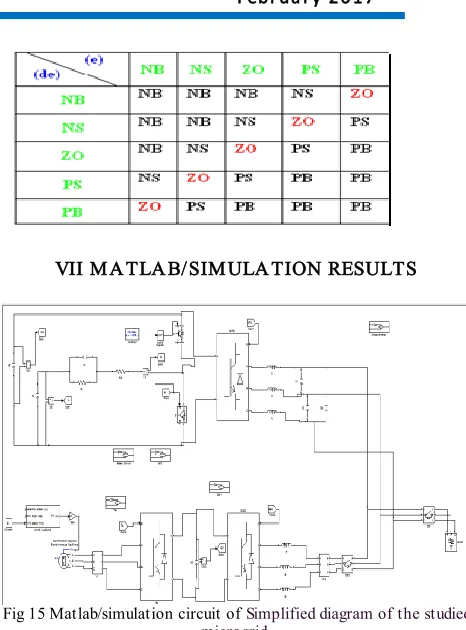
The objective of this dissertation is to control the output voltage of the boost converter. The error and change of error of the output voltage will be the inputs of fuzzy logic controller. These 2 inputs are divided into five groups; NB: Negative Big, NS: Negative Small, ZO: Zero Area, PS: Positive small and PB: Positive Big and its parameter [10]. These fuzzy control rules for error and change of error can be referred in the table that is shown in Table II as per below:
Table II: Rules for error and change of error
VII M A TLA B/SIM ULA TION RESULTS
Fig 15 Matlab/simulation circuit of Simplified diagram of the studied microgrid.
Fig 16 simulation wave form of grid voltage and current
Fig 17 simulation wave form of during the tests with a 30-Ah 12-V lead–acid battery Current and Voltage
Available online:
https://edupediapublications.org/journals/index.php/IJR/
P a g e | 130(b)
(c)
(d)
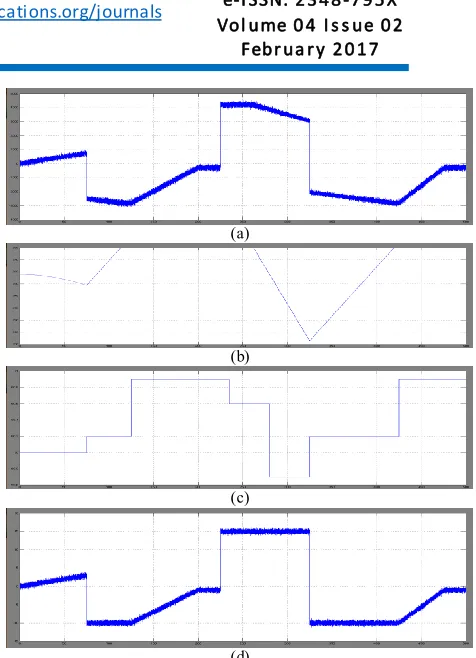
Fig 18simulation wave form of Operation with a constant wind speed of 9.2 m/s: (a) Power at the GFC terminals, (b) battery bank voltage, (c)
microgrid frequency, and (d) battery current
(a)
(b)
(c)
(d)
Fig 19 simulation wave form of peration with variable wind speed: (a) Power at the GFC terminals, (b) battery bank voltage, (c) microgrid
frequency, and (d) battery current.
(a)
(b)
(c)
(d)
Fig 20 simulation wave form of operation with variable wind speed with fuzzy controller : (a) Power at the GFC terminals, (b) battery bank
voltage, (c) microgrid frequency, and (d) battery current
VIII CONCLUSION
This paper proposed controller is a strategy to fuzzy logic control the generated power in order to keep the charging voltage battery banks under control in stand-alone microgrid with distributed renewable energy sources. This strategy does not need wired communication between the distributed renewable sources nor dump loads to dissipate the surplus of generated power in the microgrid. These technical advantages make the proposed strategy a promising tool to increase the viability and reliability of the renewable power generation system installed in isolated and remote communities. Although a wind turbine has been used to demonstrate the validity of the proposed strategy, it is also valid regardless of the power source existing in the isolated microgrid. The proposed
strategy calculates the amount
Available online:
https://edupediapublications.org/journals/index.php/IJR/
P a g e | 131REFERENCES
[1].José G. de Matos, Member, IEEE, Felipe S. F. e Silva, Student Member, IEEE, and Luiz A. de S. Ribeiro, Member, IEEE” Power Control in AC Isolated Micro grids With Renewable Energy Sources and Energy Storage Systems” IEEE T ransactions On Industrial Electronics, Vol. 62, No. 6, June 2015.
[2] L. A. de S. Ribeiro, O. R. Saavedra, S. L. de Lima, and J. G. de Matos, “Isolated micro-grid with renewable hybrid generation: The case of Lençóis island,” IEEE Trans. Sustain. Energy, vol. 2, no. 1, pp. 1–11, Jan. 2011.
[3] L. A. de S. Ribeiro, O. R. Saavedra, S. L. de Lima, and J. G. de Matos, “Making isolated renewable energy systems more reliable,” Renew. Energy, vol. 45, pp. 221–231, Sep. 2012.
[4] J. G. de Matos, L. A. de S. Ribeiro, and E. C. Gomes, “Power control in ac autonomous and isolated micro grids with renewable energy sources and energy storage systems,” in Proc. IEEE IECON, 2013, pp. 1827–1832.
[5] N. Mendis, K. M. Muttaqi, S. Pereira, and M. N. Uddin, “A novel control strategy for stand-alone operation of a wind dominated RAPS system,” in Proc. IEEE IAS Annu. Meeting, 2011, pp. 1 –8. [6] J. Chen, J. Cheng, C. Gong, and X. Deng, “Energy management and power control for a stand-alone wind energy conversion system,” in Proc. IEEE IECON, 2012, pp. 989–994.
[7] M. J. Erickson and R. H. Lasseter, “Integration of battery storage element in a CERTS microgrid,” in Proc. IEEE ECCE, 2010, pp. 2570– 2577.
[8] J. Rocabert, J. A. Luna, F. Blaabjerg, and P. Rodrígues, “Control of power converters in ac microgrids,” IEEE Trans. Power Electron., vol. 27, no. 11, pp. 4734–4749, Nov. 2012.
[9] C. Jin, P. Wang, J. Xiao, Y. T ang, and F. H. Choo, “Implementation of hierarchical control in dc microgrids,” IEEE T rans. Ind. Electron., vol. 61, no. 8, pp. 4032–4042, Feb. 2014.
[10] X. Lu, K. Sun, J. M. Guerrero, J. C. Vasquez, and L. Huang, “State-ofcharge balance using adaptive droop control for distributed energy storage systems in dc microgrid applications,” IEEE T rans. Ind. Electron., vol. 61, no. 6, pp. 2804–2815, Jun. 2014.
[11] M. A. Abusara, J. M. Guerrero, and S. M. Sharkh, “Line-interactive UPS for microgrids,” IEEE T rans. Ind. Electron., vol. 61, no. 3, pp. 1292–1300, Mar. 2014.
[12] J. M. Guerrero, P. X. Loh, T .-L. Lee, and M. Chandorkar, “Advanced control architectures for intelligent micro grids–Part II: Power quality, energy storage, ac/dc microgrids,” IEEE T rans. Ind. Electron., vol. 60, no. 4, pp. 1263–1270, Apr. 2013.