International Journal of Research (IJR)
e-ISSN: 2348-6848, p- ISSN: 2348-795X Volume 2, Issue 12, December 2015Available at http://internationaljournalofresearch.org
Improvement of Power Quality by Hybrid
Fuzzy Based Reduced-Rating Dvr with Battery Energy Storage
System
Vanapalli.Srinivas PG Scholar & Mr.K. PeddaKapu
Nova College Of Engineering And Technology Jangareddy Gudem , Department Of Electrical And Electronics Engineering , JNTUK Andhrapradesh, India.
Abstract:
In this thesis a hybrid fuzzy based reduced-rating dynamic voltage restorer (DVR) is presented for improving the power quality with a battery energy storage system. A modular control technique with addition to fuzzy control, capacitor-supported DVR is presented.
In this paper, different voltage injection schemes for dynamic voltage restorers (DVRs) are analyzed with particular focus on a new method used to minimize the rating of the voltage source converter (VSC) used in DVR.
The control of a DVR is demonstrated with a reduces-rating VCS. The reference load voltage is estimated using the unit vectors. The synchronous reference frame theory is used for the conversion of voltages from rotating vectors to the stationary frame. The compensation of the voltage sag, swell, and harmonics is demonstrated using a reduced-rating DVR. Finally it is verified in MATLAB and the simulation results here are presented.
Index Terms—Dynamic voltage restorer (DVR); Hybrid Fuzzy Controller; power quality; voltage harmonics; voltage sag; and voltage swells
1.INTRODUCTION
POWER QUALITY problems in the present-day distribution systems are addressed in the literature [1]–[6] due to the increased use of sensitive and critical equipment pieces such as communication
network, process industries, and precise
manufacturing processes. Power quality problems such as transients, sags, swells, and other distortions to the sinusoidal waveform of the supply voltage affect the performance of these equipment pieces. Technologies such as custom power devices are emerged to provide
protection against power quality problems [2]. Custom power devices are mainly of three categories such as series-connected compensators known as dynamic voltage restorers (DVRs),
shunt-connected compensators such as
distribution static compensators, and a
combination of series and shunt-connected compensators known as unified power quality conditioner [2]–[6]. The DVR can regulate the load voltage from the problems such as sag, swell, and harmonics in the supply voltages. Hence, it can protect the critical consumer loads from tripping and consequent losses [2]. The custom power devices are developed and installed at consumer point to meet the power quality standards such as IEEE-519 [7].
Voltage sags in an electrical grid are not always possible to avoid because of the finite clearing time of the faults that cause the voltage sags and the propagation of sags from the transmission and distribution systems to the low-voltage loads. Voltage sags are the common reasons for interruption in production plants and for end-user equipment malfunctions ingeneral.
In particular, tripping of
equipment in a production line can cause production interruption and significant costs due to loss of production. One solution to this problem is to make the equipment itself more tolerant to sags, either by intelligent control or by storing ―ride-through‖ energy in the equipment.
International Journal of Research (IJR)
e-ISSN: 2348-6848, p- ISSN: 2348-795X Volume 2, Issue 12, December 2015Available at http://internationaljournalofresearch.org
longer power interruptions or a DVR on the incoming supply to mitigate voltage sags for shorter periods [8]–[23]. DVRs can eliminate most of the sags and minimize the risk of load tripping for very deep sags, but their main drawbacks are their standby losses, the equipment cost, and also the protection scheme required for downstream short circuits. Many solutions and their problems using DVRs are reported, such as the voltages in a three-phase system are balanced [8] and an energy-optimized control of DVR is discussed in [10].
Industrial examples of DVRs are given in [11], and different control methods are analyzed for different types of voltage sags in [12]–[18]. A comparison of different topologies and control methods is presented for a DVR in [19]. The design of a capacitor-supported DVR that protects sag, swell, distortion, or unbalance in the supply voltages is discussed in [17]. The performance of a DVR with the high-frequency-link transformer is discussed in [24]. In this paper, the control and performance of a DVR are demonstrated with a reduced-rating voltage source converter (VSC). The synchronous reference frame (SRF) theory is used for the control of the DVR.
2.CASE STUDY OF PROPOSED THEORY OPERATION OF DVR
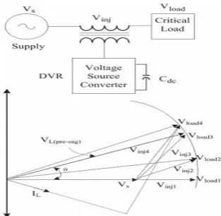
The schematic of a DVR-connected system is shown inFig. 1(a). The voltageVinj is inserted such that the load voltage Vload is constant in magnitude and is undistorted, although the supply voltage Vs is not constant in magnitude or is distorted. Fig. 1(b) shows the phasor diagram of different voltage
Fig. 1. (a) Basic circuit of DVR. (b) Phasor diagram of the DVR voltage injection schemes.
injection schemes of the DVR. VL(pre−sag) is a voltage across the critical load prior to the voltage sag condition. During the voltage sag, the voltage is reduced to Vs with a phase lag angl ofθ. Now, the DVR injects a voltage such that the load voltage magnitude is maintained at the pre-sag condition. According t the phase angle of the load voltage, the injection of voltages can be realized in four ways [19].Vinj1 represents the voltage injected in-phase with the supply voltage. With the injection ofVinj2, the load voltage magnitude remains same but it lead Vs by a small angle.
International Journal of Research (IJR)
e-ISSN: 2348-6848, p- ISSN: 2348-795X Volume 2, Issue 12, December 2015Available at http://internationaljournalofresearch.org
A three-phase DVR is connected to the line to inject a voltage in series using three single-phase transformers Tr. Lr andCr represent the filter components used to filter the ripples in the injected voltage. A three-leg VSC with insulated-gate bipolar transistors (IGBTs) is used as a DVR,
and a BESS is connected to its dc bus.
Fig. 2. Schematic of the DVR-connected system.
2.1 CONTROL OF DVR
he compensation for voltage sags using a DVR can be performed by injecting or absorbing the reactive power or the real power [17]. When the injected voltage is in quadrature with the current at the fundamental frequency, the compensation is made by injecting reactive power and the DVR is with a self-supported dc bus. However, if the injected voltage is inphase with the current, DVR injects real power, and hence, a battery is required at the dc bus of the VSC. The control technique adopted should consider the limitations such as the voltage injection capability
(converter and transformer rating) and
optimization of the size of energy storage.
2.1.1 Control Of Dvr With Bess For Voltage Sag,
Swell And Harmonics And Harmonic
Compensation
Fig. 3 shows a control block of the DVR in which the SRF theory is used for reference signal estimation. The voltages at the PCC vS and at the load terminal vLare sensed for deriving the IGBTs’ gate signals. The reference load voltage
V∗L is extracted using the derived unit vector
[23]. Load voltages (VLa,VLb,VLc) are
converted to the rotating reference frame using abc−dqo conversion using Park’s transformation with unit vectors(sin,θ,cos,θ)derived using a phase-locked loop as
(1)
Similarly, reference load
voltages(V∗La,V∗Lb,V∗ Lc )and voltages at the
PCCvSare also converted to the rotating reference frame. Then, the DVR voltages are obtained in the rotatingreference frame as
(2)
(3)
Fig. 3. Control block of the DVR that uses the SRF method of control.
Fig. 4. (a) Schematic of the self-supported DVR. (b) Control block of the DVR that uses the SRF method of control.
International Journal of Research (IJR)
e-ISSN: 2348-6848, p- ISSN: 2348-795X Volume 2, Issue 12, December 2015Available at http://internationaljournalofresearch.org
(4)
(5)
The error between the reference and actual DVR voltages in the rotating reference frame is regulated using two proportional–integral (PI)
controllers. Reference DVR voltages in
theabcframe are obtained from a reverse Park’s
transformation taking ∗ Ddfrom (4),V ∗ Dq from
(5),V ∗
D0 as zero as
(6)
Reference DVR voltages (v∗ dvra ,v ∗ dvrb ,v ∗
dvrc ) and actual DVR
voltages(vdvra,vdvrb,vdvrc) are used in a pulse width modulated (PWM) controller to generate gating pulses to a VSC of the DVR. The PWM controller is operated with a switching frequency of 10 kHz.
B. Control of Self-Supported DVR for Voltage Sag, Swell, and
Harmonics Compensation Fig. 4(a) shows a schematic of a capacitor-supported DVR connected to three-phase critical loads, and Fig. 4(b) shows a control block of the DVR in which the SRF theory is used for the control of self-supported DVR. Voltages at the PCC vS are converted to the rotating reference frame using abc−dqo conversion using Park’s transformation. The harmonics and the oscillatory components of the voltage are eliminated using low pass filters (LPFs). The components of voltages in thed- and q-axes are
(7)
(8)
The compensating strategy for
compensation of voltage quality problems considers that the load terminal voltage should be of rated magnitude and undistorted. In order to maintain the dc bus voltage of the self-supported capacitor, a PI controller is used at the dc bus voltage of the
Fig. 5. MATLAB-based model of the BESS-supported DVR-connected system.
DVR and the output is considered as a voltagevcapfor meeting its losses
(9)
wherevde(n) =v dc−vdc(n) is the error between
the reference v∗dcand sensed dc voltagesvdcat
thenth sampling instant.Kp1andKi1are the
proportional and the integral gains of the dc busvoltage PI controller.The referenced-axis load voltage is therefore expressed asfollows:
(10)
The amplitude of load terminal voltageVLis
controlled to itsreference voltage V ∗ L using
another PI controller. The output of the PI controller is considered as the reactive component of voltagevqrfor voltage regulation of the load
terminal voltage. The amplitude of load
International Journal of Research (IJR)
e-ISSN: 2348-6848, p- ISSN: 2348-795X Volume 2, Issue 12, December 2015Available at http://internationaljournalofresearch.org
(11)
Then, a PI controller is used to regulate this to a reference value as
(12)
wherevte(n) =V ∗ L−VL(n) denotes the error
between the reference ∗ L and actualVL(n) load
terminal voltage amplitudes at thenth sampling instant.Kp2andKi2are the proportional and the integral gains of the dc bus voltage PI controller. The reference load quadrature axis voltage is expressed as follows:
(13)
Reference load voltages(v ∗ La ,v ∗ Lb ,v ∗ Lc ) in
the abc frame are obtained from a reverse Park’s transformation as in (6). The error between sensed load voltages(vLa,vLb,vLc)and reference load voltages is used over a controller to generate gating pulse to the VSC of the DVR.
MODELING AND SIMULATION
The DVR-connected system consisting of a three-phase supply, three-three-phase critical loads, and the series injection transformers shown in Fig. 2 is modeled in MATLAB/Simulink environment along with a sim power system toolbox and is shown in Fig. 5. An equivalent load considered is a 10-kVA 0.8-pf lag linear load. The parameters of the considered system for the simulation study are given in the Appendix
Fig. 6. Dynamic performance of DVR with in-phase injection during voltage sag and swell applied to critical load.
The control algorithm for the DVR shown in Fig. 3 is also modeled in MATLAB. The reference DVR voltages are derived from sensed PCC voltages (vsa,vsb,vsc) and load voltages (vLa,vLb,vLc). A PWM controller is used over the reference and sensed DVR voltages to generate the gating signals for the IGBTs of the VSC of the DVR. The capacitor-supported DVR shown in Fig. 4 is also modeled and simulated in MATLAB, and the performances of the systems are compared in three conditions of the DVR.
PERFORMANCE OF THE DVR SYSTEM
The performance of the DVR is
demonstrated for different supply voltage
International Journal of Research (IJR)
e-ISSN: 2348-6848, p- ISSN: 2348-795X Volume 2, Issue 12, December 2015Available at http://internationaljournalofresearch.org
harmonics in the supply voltages is demonstrated in Fig. 8. At 0.2 s, the supply voltage is distorted and continued for five cycles. The load voltage is maintained sinusoidal by injecting proper compensation voltage by the DVR. The total harmonics distortions (THDs) of the voltage at the PCC, supply current,
Fig. 7. Voltages at the PCC and load terminals.
and load voltage are shown in Figs. 9–11, respectively. It is observed that the load voltage THD is reduced to a level of 0.66% from the PCC voltage of 6.34%. The magnitudes of the voltage injected by the DVR for mitigating the same kinds of sag in the supply with different angles of injection are observed. The injected voltage, series current, and kilo volt ampere ratings of the DVR for the four injection schemes are given in Table I. In Scheme-1 in Table I, the in-phase injected voltage is Vinj1 in the phasor diagram in Fig. 1. In Scheme-2, a DVR voltage is injection at a small angle of 30 ◦ , and in Scheme-3, the DVR voltage is injected at an angle of 45◦ . The injection of voltage in quadrature with the line
Fig. 8. Dynamic performance of DVR during harmonics in supply voltage applied to critical
load.
Fig. 9. PCC voltage and harmonic spectrum during the disturbance.
Fig. 10. Supply current and harmonic spectrum during the disturbance
Fig. 11. Load voltage and harmonic spectrum during the disturbance.
TABLE I
International Journal of Research (IJR)
e-ISSN: 2348-6848, p- ISSN: 2348-795X Volume 2, Issue 12, December 2015Available at http://internationaljournalofresearch.org
FORSAGMITIGATION
current is in Scheme-4. The required rating of compensation of the same using Scheme-1 is much less than that of Scheme-4.The performance of the self-supported DVR (Scheme-4) for compensation of voltage sag is shown in Fig. 12(a) and that of a voltage swell is shown in Fig. 12(b). It is observed that the injected voltage is in quadrature with the supply current, and hence, a capacitor can support the dc bus of the DVR. However, the injected voltage is higher compared with an inphase injected voltage (Scheme-1).
Fig. 12. Dynamic performance of the capacitor-supported DVR during (a) voltage sag and (b) voltage swell applied to critical load.
FUZZY LOGIC CONTROLLED
RESULTS:
Fig 7.5: Fuzzy Controlled PCC voltage and harmonic spectrum during the disturbance.
Fig 13 Fuzzy controlled load voltage and
harmonic spectrum during the disturbance.
CONCLUSION
The operation of a DVR has been demonstrated with a new control technique using various voltage injection schemes. A comparison of the performance of the DVR with different schemes has been performed with a reduced-rating VSC, including a capacitor-supported DVR. The reference load voltage has been estimated using the method of unit vectors, and the control of DVR has been achieved, which minimizes the error of voltage injection. The SRF theory has been used for estimating the reference DVR voltages. It is concluded that the voltage injection in-phase with the PCC voltage results in minimum rating of DVR but at the cost of an energy source at its dc bus.
APPENDIX
AC line voltage: 415 V, 50 Hz
Line impedance: Ls=3.0mH,Rs=0.01 Ω Linear loads: 10-kVA 0.80-pf lag Ripple filter: Cf =10μF,Rf =4.8Ω DVR with BESS
DC voltage of DVR: 300 V AC inductor: 2.0 mH
Gainsofthed-axis PI controller: Kp1=0.5,
International Journal of Research (IJR)
e-ISSN: 2348-6848, p- ISSN: 2348-795X Volume 2, Issue 12, December 2015Available at http://internationaljournalofresearch.org
Gainsoftheq-axis PI controller: Kp2=0.5,
Ki2=0.35
PWM switching frequency: 10 kHz DVR with dc bus capacitor supported DC voltage of DVR: 300 V
AC inductor: 2.0 mH
DC bus voltage PI controller: Kp1=0.5, Ki1=0.35 AC load voltage PI controller: Kp2=0.1, Ki2=0.5 PWM switching frequency: 10 kHz
Series transformer: three-phase transformer of rating 10 kVA, 200 V/300 V.
REFERENCES
[1] M. H. J. Bollen,Understanding Power Quality Problems—Voltage Sags and Interruptions. New York, NY, USA: IEEE Press, 2000.
[2] A. Ghosh and G. Ledwich, Power Quality Enhancement Using Custom Power Devices. London, U.K.: Kluwer, 2002. [3] M. H. J. Bollen and I. Gu, Signal Processing of Power Quality Disturbances. Hoboken, NJ, USA: Wiley-IEEE Press, 2006.
[4] R. C. Dugan, M. F. McGranaghan, and H. W. Beaty, Electric Power Systems Quality, 2nd ed. New York, NY, USA: McGraw-Hill, 2006.
[5] A. Moreno-Munoz, Power Quality: Mitigation Technologies in a Distributed Environment. London, U.K.: Springer-Verlag, 2007.
[6] K. R. Padiyar, FACTS Controllers in Transmission and Distribution. New Delhi, India: New Age Int., 2007.
[7] IEEE Recommended Practices and
Recommendations for Harmonics Control in Electric Power Systems, IEEE Std. 519, 1992.
[8] V. B. Bhavraju and P. N. Enjeti, ―An active line conditioner to balance voltages in a three phase system,‖IEEE Trans. Ind. Appl., vol. 32, no. 2, pp. 287–292, Mar./Apr. 1996.
[9] S. Middlekauff and E. Collins, ―System and customer impact,‖ IEEE Trans. Power Del., vol. 13, no. 1, pp. 278–282, Jan. 1998.
[10] M. Vilathgamuwa, R. Perera, S. Choi, and K. Tseng, ―Control of energy optimized dynamic voltage restorer,‖ inProc. IEEE IECON, 1999, vol. 2, pp. 873–878.
[11] J. G. Nielsen, F. Blaabjerg, and N. Mohan, ―Control strategies for dynamic voltage restorer compensating voltage sags with phase jump,‖ inProc.IEEE APEC, 2001, vol. 2, pp. 1267–1273.
[12] A. Ghosh and G. Ledwich, ―Compensation of distribution system voltage using DVR,‖IEEE Trans. Power Del., vol. 17, no. 4, pp. 1030– 1036,Oct. 2002.
[13] A. Ghosh and A. Joshi, ―A new algorithm for the generation of reference voltages of a DVR using the method of instantaneous symmetrical components,‖ IEEE Power Eng. Rev., vol. 22, no. 1, pp. 63–65,Jan. 2002.
[14] I.-Y. Chung, D.-J. Won, S.-Y. Park, S.-I. Moon, and J.-K. Park, ―TheDC link energy control method in dynamic voltage restorer system,‖ Int. J. Elect. Power Energy Syst., vol. 25, no. 7, pp. 525–531,Sep. 2003.
[15] E. C. Aeloíza, P. N. Enjeti, L. A. Morán, O. C. Montero-Hernandez, andS. Kim, ―Analysis and design of a new voltage sag compensator for critical loads in electrical power distribution systems,‖ IEEE Trans. Ind. Appl., vol. 39, no. 4, pp. 1143–1150, Jul./Aug. 2003.
[16] J. W. Liu, S. S. Choi, and S. Chen, ―Design of step dynamic voltage regulator for power quality enhancement,‖IEEE Trans. Power Del., vol. 18,no. 4, pp. 1403–1409, Oct. 2003.
[17] A. Ghosh, A. K. Jindal, and A. Joshi, ―Design of a capacitor supporteddynamic voltage restorer for unbalanced and distorted loads,‖IEEE Trans.Power Del., vol. 19, no. 1, pp. 405–413, Jan. 2004.
International Journal of Research (IJR)
e-ISSN: 2348-6848, p- ISSN: 2348-795X Volume 2, Issue 12, December 2015Available at http://internationaljournalofresearch.org
[19] J. G. Nielsen and F. Blaabjerg, ―A detailed comparison of system topologies for dynamic voltage restorers,‖IEEE Trans. Ind. Appl., vol. 41, no. 5,pp. 1272–1280, Sep./Oct. 2005.
[20] M. R. Banaei, S. H. Hosseini, S.
Khanmohamadi, and G. B. Gharehpetian,
―Verification of a new energy control strategy for dynamic voltage restorer by simulation,‖Simul. Model. Pract. Theory, vol. 14, no. 2, pp. 112–125, Feb. 2006.
[21] A. K. Jindal, A. Ghosh, and A. Joshi, ―Critical load bus voltage control using DVR under system frequency variation,‖Elect. Power Syst. Res., vol. 78, no. 2, pp. 255–263, Feb. 2008.
[22] D. M. Vilathgamuwa, H. M. Wijekoon, and S. S. Choi, ―A novel technique to compensate voltage sags in multiline distribution system—The interline dynamic voltage restorer,‖IEEE Trans. Ind. Electron., vol. 53, no. 5, pp. 1603–1611, Oct. 2006.
[23] A. Chandra, B. Singh, B. N. Singh, and K. Al-Haddad, ―An improved control algorithm of shunt active filter for voltage regulation, harmonic
elimination, power-factor correction, and
balancing of nonlinear loads,‖ IEEE Trans. Power Electron., vol. 15, no. 3, pp. 495–507, May 2000.