6UJMJUZ$VSSFOU$PNQFOTBUJPO0G/POMJOFBS-PBE#Z1W"DUJWF
1PXFS'JMUFS$PNCJOBUJPO6TJOH'V[[Z
1Mr.KALANGI RAJIV 2Mr. N.MANGILAL JADAV
Laqshya Institute of Technology and Sciences, Khammam, Telangana State ,India.
Abstract- In this paper, a phase three-wire system, as well as a detailed PV generator, dc/dc boost convertor to extract maximum radiation power using maximum power point tracking, associate degreed dc/ac voltage source convertor to act as an APF, is presented. A source is said to be renewable if there's no obvious limit on its availability. It may be used over and over again because it continues to replace itself. Sunshine, wind and water from rain are so renewable. sustainable resource use is that meets our present needs without compromising the power of future generations to satisfy their needs. The photovoltaic (PV) generation is more and more popular these days, while typical loads need additional high-power quality. Basically, one PV generator supply to nonlinear loads is desired to be integrated with a function as an active power filter (APF). The instantaneous power theory is applied to design the PV-APF controller, that shows reliable performances. Here fuzzy logic is used for controlling compared to other controllers The MATLAB/SimpowerSystems tool has proved that the combined system will at the same time inject maximum power from a PV unit and compensate the harmonic current drawn by nonlinear loads.
INDEX TERMS Active power filter (APF), instantaneous power theory, photovoltaic (PV), power quality, renewable energy.
I.INTRODUCTION
Now a days renewable energy resources demand is going on increasing due to power demand and decreasing of the fossil fuels. And also the requirement of power quality is very essential concern along with power supply realiability. The grid-connected photovoltaic (PV) generator has today become more popular because of its reliable performance and its ability to come up with power from clean energy resources. The dc output voltage of PV arrays is connected to a dc/dc boost converter using a most power point tracking (MPPT) controller to maximize their produced energy. Then, that converter is coupled to a dc/ac voltage source device (VSC) to let the PV system push electric power to the ac utility. The local load of the PV system can specifically be a nonlinear load, such as computers, compact fluorescent lamps, and plenty of different
home appliances, that needs distorted currents. Development of a method to compensate the distribution system harmonics is equally urgent. during this case, PV generators should provide the utility with distorted compensation capability, that makes currents injected/absorbed by the utility to be sinusoidal. Therefore, the harmonic compensation function is realized through flexible control of dc/ac VSC. instantaneous power theory has successfully completed active power filter (APF) designing with good performance. However, the PV-APF combination has simply been gradually developed for several years. this combination is capable of simultaneously compensating power factor, current imbalance, and current harmonics, and also of injecting the energy generated by PV with low total harmonic distortion (THD).
Even once there is no energy available from PV, the combination will still operate to enhance the power quality of the utility. After that, the control techniques are improved in some later efforts to develop PV inverters with real power injection and APF features. However, their research did not show consistent results obtained by their projected theories, and they are applicable for a single-phase PV only. The PV-APF system helps the utility supply a unity power issue and pure curved currents to the local nonlinear loads by generating the oscillating and imaginary components. once there's an excess power, that PV unit can only inject average power to the utility. As a result, this system is considered as a distributed APF, which is a better solution than adopting passive filters or centralized APFs. the most contributions of this paper ar threefold.
1) For the first time, a fully complete PV-APF combination system is presented.
2) The controller based on instantaneous power theory and instantaneous power balance is proposed to replace the conventional dq-current controller for a PV unit.
3) Flexible operation modes of the PV-APF combination system are possible in the proposed model.
/ŶƚĞƌŶĂƚŝŽŶĂů:ŽƵƌŶĂůŽĨZĞƐĞĂƌĐŚ
ǀĂŝůĂďůĞĂƚ ŚƚƚƉƐ͗ͬͬĞĚƵƉĞĚŝĂƉƵďůŝĐĂƚŝŽŶƐ͘ŽƌŐͬũŽƵƌŶĂůƐ ƉͲ/^^E͗ϮϯϰϴͲϲϴϰϴ ĞͲ/^^E͗ϮϯϰϴͲϳϵϱy sŽů ƵŵĞϬϰ/Ɛ Ɛ ƵĞϬϯDĂ ƌĐŚϮϬϭϳ
II. PV-APF COMBINATION SYSTEM
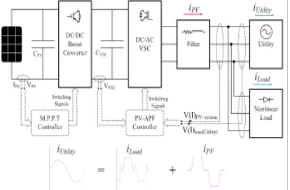
The PV-APF configuration is shown in Fig. 1, which consists of the following.
1) The PV 5series-66parallel array, which is SunPower SPR-305-type, delivers a maximum of 100-[kW] power at 1000-W/m2 solar irradiance, assuming that there is no battery energy storage system connected to the dc bus.
Figure 1. Proposed design of PV-APF combination.
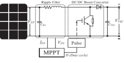
2) A 5-kHz boost dc/dc converter implements MPPT by an incremental conductance–integral regulator technique, that automatically varies the duty cycle so as to generate the desired voltage to extract maximum power.
3) The dc bus is connected to a two-level three-phase dc/ac VSC with a CVSC capacitor. The dc/ac VSC converts the 500 [V] dc to 260 [V]/60 [Hz] ac supplying to local nonlinear loads and connects to a stiff utility. The dq-current and PV-APF and APF controllers square measure applied for this dc/ac VSC afterward.
4) A 10-kVAr capacitor bank filters out switching harmonics produced by the dc/ac VSC.
5) the loads include a three-phase diode rectifier supplying a current of 450 or 50 [A] at dc side and one phase diode rectifier with 50-[A] dc current connecting between phase A and phase B to create an overall unbalanced load.
6) This PV-APF combination system is connected on to the utility for shunt active filter implementation.
A. DYNAMIC MODEL OF PV ARRAY
The dynamic model of PV cell is shown in Fig. 2. PV array consists of N string connected in parallel and every string consists of M number of modules connected in series.
Figure 2. Equivalent electrical circuit of the PVcell.
The output-terminal current I is equal to the light generated current IL, less the diode-current Id and also the shunt leakage current (or ground-shunt current) ISh. The series resistance RS represents the internal resistance to the current flow. The shunt resistance RSh is inversely related to leakage current to the ground. In an ideal PV cell, RS = zero (no series loss) and RSh = infinite (no outpouring to ground). in a typical high-quality 1-in2 silicon cell, RS = 0.05–0.10 and RSh = 200–300.
The PV conversion efficiency is sensitive to small variations in RS, however is insensitive to variations in RSh. A little increase in RS will decrease the PV output considerably. the 2 most significant parameters mostly used for describing the cell electrical performance are the open-circuit voltage Voc = Vout + RSI obtained once the load current is zero (I = 0) and also the short-circuit current Isc. Ignoring the little diode and the ground-leakage currents below zero terminal voltage, the short-circuit current below this condition is that the photocurrent IL. the basic equation describing the I– V characteristic of a practical PV cell is
I = I−I −I!"−I#$%&)*+,'(−1- −&./031234
56 (1)
where ID is the saturation current of the diode, Q is the electron charge (1.6 × 10⁻¹⁹ C), A is the curve
fitting constant (or diode emission factor), K is the Boltzmann constant (1.38×10⁻²³ J/◦K), andT (◦K) is
the temperature on absolute scale. The ISh, that, in practical cells, is smaller than IL andId, can be ignored.
B. MPPT IN DC/DC CONVERTER
Figure 3. I–V curve and remarkable points.
In this proposed method DC/DC converter is placed to maintain the optimal voltage and gaining the maximum voltage by using the MPPT control. In this paper, switching duty cycle is optimized by the MPPT controller that uses the incremental conductance and integral regulator technique. This MPPT method is based on the fact that the power slope of the PV is null at MPP point (where dp/dv = 0), positive in the left, and negative in the right. The cell produces the maximum power at voltage corresponding to the knee point of the I–V curve, as shown in Fig. 3. Vmax and Imax are voltage and current at maximum power point, respectively. In the following equations, dv and di are obtained by one-sample delayed values:
=
( )
= i + v
= 0 (2)
The regulator output of MPPT is the duty cycle correction for semiconductor switches. In summary, the controller of the dc/dc boost converter is shown in Fig. 4.
Figure 4. Controller mechanism of the boost converter.
III. INSTANTANEOUS POWER BALANCE
Instantaneous power flow among the components of the PV-APF system simplified in Fig. 5 may be a compromise between technical constraints and designed targets.
Figure 5. Instantaneous power flows among the PV-APF system.
The dc/dc boost convertor regulates its semiconductor switches to extract the utmost power generated by PV array (pPV). The MPPT methods might be chosen appropriately in any specific circumstance. beyond that convertor with the power output pDC, the dc/ac VSC keeps a major role in implementing a given control duty. At the dc side, the power idea is consistent. However, at the ac side, the instantaneous power includes both the active half (pVSC) and the imaginary part (qVSC). The losses at the dc/dc boost convertor and the dc/ac VSC are neglected.
P!"≈P$%≈P"&%. (3)
The load demand includes real power and imaginary power. In general, the real and imaginary power include two parts: 1) an average (superscript ¯) one, and 2) an oscillating (superscript ˜) one, which are realized through a low-pass filter (LPF) (or rarely a high-pass filter)
'P"&%P)= P= P("&%()+ P+ P()("&% q)= q*)+ q*)
(4)
The APF function results in pure sinusoidal currents from the utility.. In general, there are two cases of utility power flow:
1) PV supplies enough power for local nonlinear loads and injects its excess power to the utility; 2) PV supplies one part of nonlinear loads consuming and the other part of load power is received from the utility.
Real power p is calculated using v, i at ac side which is the same as in dc side VPV × IPV of the PV if no loss while the imaginary power is calculated at ac side only. The average real power p¯ represents the energy flow per time in one direction only that is effectively converted into work and, therefore, has to be supplied from the utility if the PV does not provide enough of this power to the load
demand, while oscillating real power p˜ represents oscillating energy flow per time. q¯ power corresponds to conventional three phase reactive power and does not contribute to transferred power while q˜ power is exchanged among three phases..
There is an instantaneous power balance among the three parts at the point of common coupling (PCC). If the PV-APF combination can supply undesirable powers to the load, the utility will supply only average part of the real power. Under that circumstance, sinusoidal currents are obtained. The controlling mechanism is to define those undesirable powers from the load and then to make the PV-APF combination generate it. Obviously, the rest of the required power is supplied from the utility. Fig. 5 illustrates case 2, where the utility has to inject one part of active power (pUti) for the load. In this case, the pure fed currents from the utility will be easily realized using an APF function, which means that it provides only the average components. The balanced relation among instantaneous powers in Fig. 5 is clarified in the following equations:
⎩ ⎪⎨ ⎪
⎧ PUti = pqVSC = qL#Uti pVSC + pUti = PL p
#VSC + p#Uti = p#L p#VSC = p#L
(5)
The dc/ac VSC modulates real and imaginary power balance among those parts of system.
IV. CONTROLLERS FOR DC/AC CONVERTER
In this section, the controllers for dc/ac VSC based on instantaneous power theory and instantaneous power balance are presented. In a conventional way, the dq-current controller is used to inject maximum real power from PV and zero reactive power to keep unity power factor of the utility. While a nonlinear load is connected close to PV position, the proposed unique PV-APF controller should be used to compensate the harmonics and help transfer the PV power. At night (no irradiance and no battery) or when there is no PV array, the APF controller is switched into the system in order to operate the CVSC capacitor just for an APF purpose.
A. PV-APF CONTROLLER
The dc/ac VSC integrated by an APF function should provide the harmonic elimination and reactive power compensation and simultaneously inject the maximum power generated by PV units. The controller is established based on the instantaneous power theory, where all the parameters
are processed instantaneously. The input signals of that controller include utility voltages (vabc), nonlinear load currents (iabcL), output currents of dc/ac VSC (iabc VSC), utility injected currents (iabcUti), and dc-link voltage VVSC (to prevent overcharge dc-link capacitor).
$%&-&==%'()-'()++%*+,-*+, (6)
Since the target is laid on the load, its consuming power is continuously measured and analyzed. Using the Clarke transformation, the instantaneous real power (pL) and imaginary power (qL) of the load can be calculated, as shown in the following equations:
.//0(,0)
12,134=5 6 78
1 −:6 −:6
0 √76 −√76< 8
/=(,=>)
/?2(,?>)3
/@2(,@>)3
< (7)
A%->>B=C /−/0 D
1 /0E C, 0
,1E (8)
In general, the real and imaginary power include two parts: 1) an average (superscript¯ ) one, and 2) an oscillating (superscript ˜ ) one, which are realized through an LPF (or rarely a high-pass filter). The LPF cutoff frequency must be selected carefully as to the inherent dynamics of loads that lead to compensation errors during transients. Unfortunately, the unavoidable time delay of the LPF may degrade the controller performance. In practice, a fifth-order Butterworth LPF with a cutoff frequency between 20 and 100 [Hz] has been used successfully depending on the spectral components in oscillating part that is to be compensated
$%&-&==%̅&%̅&++%̅&-#& (9)
The average part derives from the fundamental component of nonlinear load current, while the oscillating part results from the harmonics and negative-sequence components. After successful compensation, the imaginary power and the oscillating part of the real power will come from the dc/ac VSC. The utility, in that case, supplies only one fraction of the average power required from the load. The rest is supposed to be from the PV array. In addition, the dc-link voltage regulator determines an extra amount of real power (p¯ loss) that causes additional flow of energy to (from) the dc-link capacitor CVSC in order to keep its voltage around a fixed reference value (VVSCref ). Eventually,
reference powers are passed to a current references calculation block. These ideas make the following equations:
pL + pqL + qL = pL = qVSC + qVSC + pVSC + pVSC + qUti + pUtiloss
⇒"
qVSC = pL−pUti + ploss qVSC = qL−qUti
pVSC = pL qVSC = qL
(10)
⇔ %p&'()*+ = pL−q,⃗Uti−ploss
q&'()*+ = qL−qUti (11)
If the p¯ loss is supplieVSCd by the PV unit and the PV-APF combination compensates all imaginary power of load demand, (12) is changed to
%p&'()*+ = pL−q,⃗Uti−ploss
q&'()*+ = qL (12)
B. PV UNIT PERFORMANCE
V. FUZZY LOGIC CONTROLLER
In FLC, basic control action is determined by a set of linguistic rules. These rules are determined by the system. Since the numerical variables are converted into linguistic variables, mathematical modeling of the system is not required in FC.
Fig.9.Fuzzy logic controller
The FLC comprises of three parts: fuzzification, interference engine and defuzzification. The FC is characterized as i. seven fuzzy sets for each input and output. ii. Triangular membership functions for simplicity. iii. Fuzzification using continuous universe of discourse. iv. Implication using Mamdani’s, ‘min’ operator. v. Defuzzification using the height method.
TABLE I: Fuzzy Rules
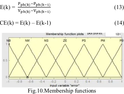
Fuzzification: Membership function values are assigned to the linguistic variables, using seven fuzzy subsets: NB (Negative Big), NM (Negative Medium), NS (Negative Small), ZE (Zero), PS (Positive Small), PM (Positive Medium), and PB (Positive Big). The Partition of fuzzy subsets and the shape of membership CE(k) E(k) function adapt the shape up to appropriate system. The value of input error and change in error are normalized by an input scaling factor.
In this system the input scaling factor has been designed such that input values are between -1 and +1. The triangular shape of the membership function of this arrangement presumes that for any particular E(k) input there is only one dominant fuzzy subset. The input error for the FLC is given as
E(k) = &./0(1)2./0(134)
/0(1)2&/0(134) (13)
CE(k) = E(k) – E(k-1) (14)
Fig.10.Membership functions
Inference Method: Several composition methods such as Max–Min and Max-Dot have been proposed in the literature. In this paper Min method is used. The output membership function of each rule is given by the minimum operator and maximum operator. Table 1 shows rule base of the FLC.
Defuzzification: As a plant usually requires a non-fuzzy value of control, a defuzzification stage is needed. To compute the output of the FLC, „height‟
method is used and the FLC output modifies the control output. Further, the output of FLC controls the switch in the inverter. In UPQC, the active power, reactive power, terminal voltage of the line and capacitor voltage are required to be maintained. In order to control these parameters, they are sensed and compared with the reference values. To achieve this, the membership functions of FC are: error, change in error and output
The set of FC rules are derived from
u=-[α E + (1-α)*C] (15)
Where α is self-adjustable factor which can regulate the whole operation. E is the error of the system, C is the change in error and u is the control variable. A large value of error E indicates that given system is not in the balanced state. If the system is unbalanced, the controller should enlarge its control variables to balance the system as early as possible. One the other hand, small value of the error E indicates that the system is near to balanced state.
VI. SIMULATION VALIDATION
The main parameters of the system used in the simulation study are indicated in Table 1. The simulation is run in a period of 0.75 s. The important time instances are: 1) at 0.05 s, turn ON MPPT and VSC dq-current controller; 2) at 0.35 s, activate MPPT; 3) at 0.5 s, switch VCS dq-current controller to PV-APF controller; 4) at 0.6 s, switch to APF controller without PV; 5) at 0.7 s, switch PV-VSC out of system; and 6) at 0.75 s, stop simulation.
Figure 6. simulation model of proposed system
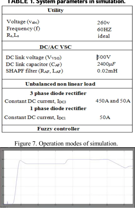
TABLE 1. System parameters in simulation.
Figure 7. Operation modes of simulation.
Figure 8. Output power of PV during running time.
(a)
(b)
Figure 9. Duty cycle and VPV changed by MPPT. (a) Output voltage of PV unit. (b) Duty cycle of
MPPT.
Active power filter performance
INTERNATIONAL JOURNAL
OF PROFESSIONAL ENGINEERING STUDIES Volume VII /Issue 1 / SEP 2016
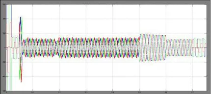
FIGURE 10. Utility supplied current waveform.
Figure 11. Utility supplied current and PCC voltage waveform.
(a)
(b)
(c)
(d)
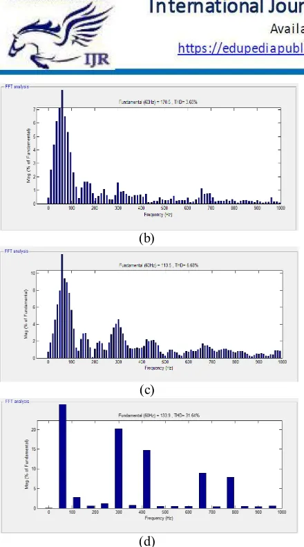
Figure 12. THD in four modes of PV system operation while utility supplies power. (a) dq-current
mode. (b) PV-APF mode. (c) APF mode. (d) Only utility supplies load.
FIGURE 13. PV supplied current waveform
.
Figure 14. Real power from the (a) utility, (b) PV unit, and (c) load, while the utility supplies power.
Figure 15. Imaginary power from the (a) utility, (b) PV unit, and (c) load, while the utility supplies power.
Figure 16. Utility received current waveform.
(a)
(b)
(c)
(d)
Figure 17. THD in four modes of PV system operation while utility receives power. (a) dq-current
mode. (b) PV-APF mode. (c) APF mode. (d) Only utility supplies load.
Figure 18. Real power from the (a) utility, (b) PV unit, and (c) load, while the utility receives power.
Figure 19. Imaginary power from the (a) utility, (b) PV unit, and (c) load, while the utility receives
power.
VI. CONCLUSION
In this paper, a PV-APF combination system with a local controller is proposed. To compensate the utility current without any harmonics The controller implements 2 purposes, that are activity power from the PV unit and filtering the harmonics of the local nonlinear load The new controller based on instantaneous power balance has Been explained consequently. The MATLAB/Simpower Systems simulation shows sensible performances of this controller. Here fuzzy controller is used compared to alternative controllers because of its accurate performance. The positive influence of MPPT on increasing PV power output is additionally valid. The shift among 3 controllers to dc/ac VSC brings different current waveforms. As a result, the conventional dq-current controller should not be applied once PV is connected to a local nonlinear load regarding power-quality viewpoint. whereas a PV unit is deactivated, the APF function will still operate. It is, therefore, technically possible for these power electronics-interfaced dg units to actively regulate the power quality of the distribution system as an auxiliary service, which will certainly make those dg units extra competitive.
REFERENCES
[1] L. Hassaine, E. Olias, J. Quintero, and M. Haddadi, ‘‘Digital power factor control and reactive power regulation for grid-connected photovoltaic inverter,’’ Renewable Energy, vol. 34, no. 1, pp. 315–321, 2009.
[2] N. Hamrouni, M. Jraidi, and A. Cherif, ‘‘New control strategy for 2-stage grid-connected photovoltaic power system,’’ Renewable Energy, vol. 33, no. 10, pp. 2212–2221, 2008.
[3] M. G. Villalva, J. R. Gazoli, and E. R. Filho, ‘‘Comprehensive approach to modeling and simulation of photovoltaic arrays,’’ IEEE Trans. Power Electron., vol. 24, no. 5, pp. 1198–1208, May 2009.
[4] N. R. Watson, T. L. Scott, and S. Hirsch, ‘‘Implications for distribution networks of high penetration of compact fluorescent lamps,’’ IEEE Trans. Power Del., vol. 24, no. 3, pp. 1521–1528, Jul. 2009.
[5] I. Houssamo, F. Locment, and M. Sechilariu, ‘‘Experimental analysis of impact of MPPT methods on energy efficiency for photovoltaic power systems,’’ Int. J. Elect. Power Energy Syst., vol. 46, pp. 98–107, Mar. 2013.
[6] M. A. G. de Brito, L. P. Sampaio, G. Luigi, G. A. e Melo, and C. A. Canesin, ‘‘Comparative analysis of MPPT techniques for PV applications,’’ in Proc. Int. Conf. Clean Elect. Power (ICCEP), Jun. 2011, pp. 99–104.
[7] M. El-Habrouk, M. K. Darwish, and P. Mehta, ‘‘Active power filters: A review,’’ Proc. IEE – Elect. Power Appl., vol. 147, no. 5, pp. 403–413, Sep. 2000. [8] H. Akagi, Y. Kanagawa, and A. Nabae, ‘‘Generalized theory of the instantaneous reactive power in three-phase circuits,’’ in Proc. Int. Conf. Power Electron., Tokyo, Japan, 1983, pp. 1375–1386. [9] Y. W. Li and J. He, ‘‘Distribution system harmonic compensation methods: An overview of DG-interfacing inverters,’’ IEEE Ind. Electron. Mag., vol. 8, no. 4, pp. 18–31, Dec. 2014.
[10] S. Kim, G. Yoo, and J. Song, ‘‘A bifunctional utility connected photovoltaic system with power factor correction and UPS facility,’’ in Proc. Conf. Rec. 25thIEEE Photovolt. Specialists Conf., May 1996,pp. 1363–1368.
Mr. KALANGI RAJIV
M.TECH (POWER ELECTRONICS )
PURSUING In Laqshya Institute of Technology Sciences ,TANIKELLA(V),KHAMMAM(D), TELANGANA, INDIA.
Email id: [email protected].
Mr. N.Mangilal Jadhav was born in India in the year of 1981. He received B.Tech degree in Electronics and
Instrumentation Engineering in the year of 2003 & M.Tech PG in Control systems in the year of 2010 from JNTUACE, JNTU Ananthapuram. He
is expert in Control Systems, Electrical Measurements, STLD, DSP, Signals& Systems, Instrumentation, Electronic Circuits Subjects. He has 10 years of Teaching experience. He is currently working as An Associate Professor in EEE Department in Laqshya Institute of Technology and Sciences, Khammam,Telangana State ,India.Email id: mangilaljadav@ gmail.com