R E S E A R C H
Open Access
Multiple access spatial modulation
Nikola Serafimovski
1*, Sinan Sinanovi´c
1, Marco Di Renzo
2and Harald Haas
1Abstract
In this study, we seek to characterise the behaviour of Spatial modulation (SM) in the multiple access scenario. By only activating a single transmit antenna for any transmission, SM entirely avoids inter-channel interference, requires no synchronisation between the transmit antennas and a single radio frequency chain at the transmitter. Most
contributions thus far have only addressed aspects of SM for a point-to-point communication system. We propose a maximum-likelihood (ML) detector which can successfully decode incoming data from multiple simultaneous transmissions and does not suffer from the near-far problem. We analyse the performance of the interference-unaware and interference-aware detectors. We look at the behaviour of SM as the signal-to-interference-plus-noise ratio goes to infinity and compare it to the complexity and cost equivalent single-input-multiple-output (SIMO) system. Two systems are considered to be equivalent in terms of complexity if their respective detection algorithms are of the same order inO(·)notation. Simulation results show that the interference-aware SM detector performs better than the complexity equivalent multi-user ML-SIMO detector by at least 3 dB at an average bit-error-ratio of 10−3.
Introduction
Multiple-antenna systems are fast becoming a key tech-nology for modern wireless systems. They offer improved error performance and higher data rates, at the expense of increased complexity and power consumption [1]. Spa-tial modulation (SM) is a recently proposed approach to multiple-input-multiple-output (MIMO) systems which entirely avoids inter-channel interference, requires no synchronisation between the transmit antennas and achieves a spatial multiplexing gain [2]. This is performed by mapping a block of information bits into a constella-tion point in the signal and spatial domains [3]. In SM, the number of information bits,, that are encoded in the spatial domain can be related to the number of transmit antennasNtasNt=2. This means that the number of transmit antennas must be a power of two unless frac-tional bit encoding [4] or generalised SM [5] are used. SM offers an intrinsic flexibility to trade off the number of transmit antennas with the modulation order in the sig-nal domain to meet the desired data rate. It should be noted that SM is shown to outperform other point-to-point MIMO schemes in terms of average bit-error-ratio (ABER) [3].
*Correspondence: n.serafi[email protected]
1Institute for Digital Communications, Joint Research Institute for Signal and Image Processing, School of Engineering, The University of Edinburgh, Edinburgh EH9 3JL, UK
Full list of author information is available at the end of the article
In the single user scenario, only a single transmit antenna is active at any instance, this avoids the need for complicated interference cancellation algorithms at the SM receiver. In addition, unlike other MIMO schemes, the number of receive antennas is independent of the num-ber of transmit antennas. Several articles are available in literature which are aimed at understanding and improv-ing the performance of SM in various scenarios, e.g., [6-8]. The study in [6] seeks to improve the ABER performance of SM by introducing trellis coding on the transmitting antennas. The study in [9] shows that the detector com-plexity of SM is independent of the number of transmit antennas. The optimal detector is known with and with-out channel state information at the receiver in [10-12]. The optimal power allocation problem for a two-transmit with one receive antenna system is solved in closed form in [13] and the performance of SM in correlated fading channels is considered in [14,15]. Recent work has also shown that SM can be combined with space–time block codes to attain spectral efficiency gains [16] by exploit-ing transmit-side diversity. At this point, it is worth notexploit-ing that if we choose to use only the spatial constellation of SM to transmit information, then SM is reduced to space-shift-keying (SSK) as proposed in [17]. To this extent, we note that all presented work can be extended to SSK without loss of generality.
MIMO techniques can also be used in relaying networks to improve the diversity, provide multiplexing gains and
aid in interference cancellation. To this extent, the orthog-onal decode and forward (DF) algorithm decodes the received signal at the relay, then re-encodes and retrans-mits this information, establishing a regenerative system. Outage probabilities, mutual information calculations and transmit diversity bounds for orthogonal amplify and for-ward (AF) and DF relaying are derived in [18] with the end-to-end performance being considered in [19] where DF is shown to perform better in terms of the ABER when compared to AF. However, the ABER of regenerative sys-tems depends on the ABER on the individual links. In particular, since SM is shown to outperform other spatial multiplexing techniques on a single link, the application of SM to relaying systems is also shown to provide sig-nificant signal-to-noise ratio (SNR) gains when compared to orthogonal DF [20]. Nonetheless, these results are only applicable in a noise-limited relaying system. The deploy-ment of relaying systems around the cell edges, how-ever, may result in interference-limited systems. There-fore, to enable the deployment of SM in a relaying scenario, the ABER performance of SM on a single link must also be assessed in the interference-limited environment.
Most contributions thus far, however, have only addressed SM aspects for point-to-point communication systems, i.e. the single user scenario. Notable exceptions are given in [21,22], where the authors focus their anal-ysis on scenarios employing SSK. The aim of this study is to characterise the behaviour of SM in the multi-user, interference-limited scenario and compare it to the com-plexity and cost equivalent multi-user MIMO system. We emphasise that SM requires only a single radio fre-quency (RF) chain at the transmit side since only one is active at any particular instance. Requiring only a single RF chain at the transmitter means that multi-user SM is not comparable in terms of cost to the more compli-cated spatial-multiplexing multi-user systems analysed in [23-26].
Furthermore, the study in [27] shows that the most energy consuming part of a wireless base station is the power amplifiers and consequently RF chains associated with each transmitter. The study in [28] demonstrates that the power requirements of a base station increase lin-early with the number of RF chains added. In addition to higher power consumption, multiple RF chains imply higher manufacturing costs and inter-antenna synchroni-sation problems. To this extent, SM is an optimal system for utilising the advantages of multiple transmit anten-nas while still maintaining a single RF chain for Green communications. The aggregate power usage in a sys-tem employing SM is significantly lower than a syssys-tem employing classical MIMO techniques. Furthermore, the lower detection complexity for SM reduces mobile sta-tion power usage, enabling a longer battery life for the
mobile terminal [9]. Understanding the performance of SM in a multi-user system is necessary to assess its suit-ability for practical deployment scenarios. In this context, it is of interest if the particular structure of the SM encod-ing scheme can be exploited to devise novel multi-user detection techniques.
In this study, we first characterise the performance of a single user detector as applied in an interference-limited scenario, i.e. we analyse a ML interference-unaware opti-mal receiver. We then propose an ML detector which can successfully decode incoming data in the multi-user sce-nario and is not interference limited, i.e. an interference-aware detector which can successfully decode data from several nodes. For each detector, we develop an analytical framework to support simulation results and closed form solutions are provided to compute the ABER over iden-tical and independently distributed (i.i.d.) Rayleigh fading channels.
The remainder of this article is organised as follows. In the “System model” section, the system and channel models are introduced. In the “Analytical modelling and receiver design” section, the performance of SM in the multiple access scenario is characterised and the analyt-ical modelling for the multi-user detector is proposed. The “Simulation results and discussion” section provides simulation results to substantiate the accuracy of the developed analytical framework. In the “Summary and conclusions” section, we summarise and conclude this study.
System model
The basic idea of SM is to map blocks of information bits onto two information carrying units [3]: (i) a symbol, cho-sen from a complex signal-constellation diagram, and (ii) a unique antenna, chosen from the set of transmit-antennas in an antenna-array, i.e. the spatial-constellation. Jointly, the spatial and signal constellation symbols form a single SM constellation symbol. If, for example, we wish to transmit a total of 4 bits/s/Hz using SM with four available transmit antennas; then the first 2 bits would define the spatial-constellation point identifying the active antenna, while the remaining 2 bits would determine the signal-constellation point that will be transmitted.
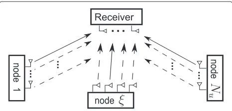
In the following work, we assume multiple nodes/users,
as shown in Figure 1. A total of Nu transmit nodes,
denoted as{1,. . .,ξ,. . .Nu}, broadcast simultaneously on the same time-frequency slot to a single receiver. Each node broadcasts a signal constellation symbol,x(u), from one of its available antennas.
The received signal at antennaris given by
yr = Nu
u=1
Emα(2u)hn(tu),rx (u)
Figure 1Multi-user SM system setup.Nodes 1,. . .,ξ,. . .Nu
broadcast simultaneously to the receiver on the same time-frequency resource block. Each solid line represents the active transmit antenna on each node to every receiving antenna. Each dashed line represents the inactive channel from every transmit antenna at a particular node to every receiving antenna.
whereEmis the average transmit energy per symbol,n(tu) is the index of the active transmit antenna from a total ofNt(u) available on nodeu,ris the index of the receive antenna from a total ofNravailable on the receiving node,
α(2u) is the power of the channel attenuation coefficients between all receive antennas and all transmit antennas on the link between node u and the receiver, hn(u)
t ,r is the fast fading channel coefficient between the active transmit antennanton nodeuand the receiving antennar,x(u)is the signal constellation symbol transmitted from the set of all possible signal constellation points,X(u), for nodeu andηr, is additive white Gaussian noise (AWGN), defined as a complex normally random variable with zero mean and varianceNo,CN(0,No).
Throughout the study EX[|x|2]=1, meaning the aver-age power in the signal constellationX(u)is normalised to one for allu. To avoid repetitive definitions of symbols, we note that symbols denoted withˆ·are simply an element of the same set as the symbol withoutˆ·, i.e.xˆcomes from the same set asx. Furthermore, all bold letters are vec-tors. If we set the signal constellation to be only a single constellation point, whereNtis chosen such that log2(Nt) equals the spectral efficiency, then all presented work can directly be applied to any system employing SSK by simply replacingx(u)=1.
Analytical modelling and receiver design
We analyse the ML detector for use in the multiple access scenario. The detector computes the Euclidean distance between the received vector signal, y, and the set of all possible received signals, selecting the closest one.
Interference-unaware detection
Starting from the system model presented in the “System model” section, the decoded pair (xest,nt)(ξ ),
formed from the estimated symbol xest emitted from
antennanton nodeξis given by
whereNt(ξ ) is the number of available transmit antennas on nodeξ,||·||Fis the Frobenius norm andX(ξ )has a total
ofM(ξ )constellation points. We note thaturepresents the index of a general node in the system, andξis the index of the desired node whose data stream is being decoded.
We can use union bound techniques to describe the behaviour of the interference-unaware SM detector in the high SNR regions. From here, we proceed to characterise the behaviour of the interference-unaware detector by defining
define the symbols at the receive antennar. With this, we can posey=A+B+η.
The pairwise error probability (PEP) can now be derived as
where(·)∗represents the complex conjugate,ηnewr is the distribution of the PEP defined byN(μ,σ2)which repre-sents the normal distribution with meanμand variance
PEP in (4) using theQ-function. Consideringηnewr and (4), we can see that the PEP can be defined as
Pr{A= ˆA|B} =Q
function. It should be noted that this PEP is valid for all channel fading statistics. We can further simplify it if we assume that the fast fading channel statistics of each ele-ment ofBare Rayleigh distributed, i.e.hn(u)
t ,r∼CN (0, 1)
and hn(u)
t has Nr number of elements. To this end, we
define
where we can see that
I∼N from the expression by taking the expectation of (5) across the fading channelhB, such that
Pr{A= ˆA} = EhB Pr{A= ˆA|hB} of the system with respect to the fast fading channelh. From here, we can apply ([29], eq. 3.66) which results in
Pr{A= ˆA} =Q
After some analytical manipulations we obtain (10)
Pr{A= ˆA} =Q
represents half of the signal-to-interference-plus-noise ratio (SINR) between nodeξand the receiver. Throughout the study, we average only across the fast fading chan-nel statistics. As (11) shows,γI is still dependent on the
magnitude of the modulated signal symbols of the inter-fering nodes,|x(u)|. This means that all expressions using
γI maintain their conditioning on the modulated signal symbols of the interfering nodes.
Given this formulation, we can now define the ABER of the single-user detector using the union bounding tech-niques in the presence of interference as
ABER(inter)ξ ≤
is defined as a fourfold summation, two for
all x(ξ ),xˆ(ξ )∈X(ξ ) and two for the indicesn(ξ )t , nˆ(ξ )t ∈
1,. . .,Nt(ξ ). In addition,dξ(b,bˆ)=dξ(nt,nˆt)+dξ(x,xˆ), wheredξ(·,ˆ·)denotes the Hamming distance between the binary representations any two symbols coming from the same set for nodeξ.
As with the interfering nodes, we assume that the desired node’s fast fading follows a Rayleigh distribution. To obtain the average PEP, we define
zr =hn(ξ )
whereσz2is the variance of SM using a variable amplitude modulation scheme. In particular, it is the variance per receive antenna of the argument inside theQ-function in (10). We define the random variable
κ= ||z||
which has a central Chi-squared distribution with 2Nr degrees of freedom given as
˜ ρK(κ)=
1 2Nr(Nr−1)!κ
where(·)! represents the factorial function. We can now
By direct inspection, we can now apply the solution to ([30], eq. 62) and obtain
EhA Pr{A= ˆA}
We note that (12) presents an analytical bound for a system employing quadrature-amplitude-modulation (QAM). If we choose to use constant-amplitude modu-lation such as phase-shift-keying (PSK), then for a fixed channel realisation, we define a=hn(ξ )
t ,r,b=x(ξ ), and pose
zPSKr = |a|ejarg(a)|b|ejarg(b)−aˆejarg(aˆ)|ˆb|ejarg(bˆ), (20)
where arg(·) represents the phase of a complex symbol. We realise that the amplitude of all constellation points is unity and thus
From the definition ofzPSKr , it is clear that its variance is defined as
In this case, (12) reduces to
ABER(ξPSK-inter)≤
The average power carried by any signal-symbol con-stellation in (12) is 1. Nonetheless, a variable amplitude modulation scheme means that the instantaneous SINR changes. The instantaneous SINR must strictly be defined to study the asymptotic behaviour of the system. This is necessary because the instantaneous SINR is an argu-ment of the PEP which is defined using theQ-function. To obtain the ABER, the PEP must be averaged across all channel realisations and all signal-symbol constellations. A closed-form expression for the asymptotic behaviour of (12) and (13) is therefore difficult to obtain. However, we note that (22) and (23) are special cases of (12) and (13) which enable a simpler theoretical analysis of the asymptotic behaviour of the system as the SINR grows to infinity. Simulation results in the “Simulation results and discussion” section show that the asymptotic bounds derived for SM using a constant amplitude modulation scheme are also valid for SM using 4-QAM. In addition, it is shown that for the point-to-point single user sce-nario, SM using PSK may have a better ABER performance than SM using QAM depending on the number of avail-able transmit antennas [31]. We now proceed with the asymptotic analysis of this system.
Asymptotic analysis of an interference-unaware detector
In this section, we investigate some asymptotic cases to highlight trends in SM at high SNR. Simulations in the “Simulation results and discussion” section show that the presented results are asymptotically tight in the high SNR region. We first define SNRξ =Emα2(ξ )/(2No) and
SIRξ =
α2(ξ ) Nu
u=ξ=1α(2u)|x(u)|2
. With these definitions, we look
at three systems, the asymptotic performance of SM and SIMO in the noise-limited scenario and the asymptotic performance of SM in the interference-limited scenario.
SNRξ 1and SINR≈SNR (noise-limited scenario)
where in the limitγI≈γ =Emα(ξ )2 /(2No). Since interfer-ence can be neglected,
lim
To simplify (26), the limit in (17) and (24) can be tackled by considering a Taylor expansion with two terms of (18) and obtain
⇒Taylor expansion (27)
f(β) ≈ 1
We realise that the average symbol-error-ratio (ASER) for SM is defined similar to the ABER and can be posed as
ASER(inter)ξ ≤ particular, this is a close approximation for ABER of SM, since the fast fading channel coefficients effectively make the SM constellation completely random at the receiver. This negates any benefits from advanced bit-to-symbol mappings such as Gray coding. In effect, the detector will create a long binary sequence which has at most 50% bit-errors within the erroneous symbol sequence, i.e. the ABER is bounded to be at most 1/2 of the ASER. The tight-ness of this bound can be seen in the “Simulation results and discussion” section. This step eliminates the depen-dence on the Hamming distance between the various SM symbols, which permits us to pose
lim
is the expectation of
σ2
z
2
−Nr
across the various possi-bilities of σz2 for x,nt,xˆ and nˆt. We are not aware of a closed form solution to the more generic expression for (30) given a variable-amplitude modulation. However, we can upper bound (30) by settingσz2=minσz2, 2. In par-ticular, the general form ofσz2is defined by the underlying SM signal-symbol constellation size,M(ξ ). To this extent, expressions for σz2 are defined using the upper bound for square QAM constellation sizes. A summary of the derivation of (32) is provided in Appendix.
WhenM(ξ )=4, then
With this in mind, the closed form of the limit is defined as
At this point, the work can be simplified by consid-ering a constant-amplitude modulation scheme such as PSK where σz2PSK is either 2 or 0 as shown in (22), then the expression in (30) is unity which simplifies further analysis. In such a scenario, however, the study in [31] shows that SM using PSK cannot always guarantee a better performance than SM using QAM. In particular, the authors of [31] demonstrate that there is a crossing point where the ABER of SM using PSK improves over SM using QAM. Nonetheless, there are two conclusions that we can drawn from this limit: (i) the system error increases with the product of the spatial constellation size,
number of receive antennas as of (35) tends to zero and is always less than 1. Since the inverse of (35) is always less than 1, the addition of an extra receive antenna implies a smaller ratio, which means a lower ABER and hence coding gains for the system.
SIMO system utilising QAM (noise-limited scenario)
To quantify the SNR difference between SM and SIMO using QAM, we need to look at the ABER performance of a SIMO system using QAM in the asymptote. We use ([32], eq. 9.23) which provides a closed form solution for the ASER of a SIMO system using QAM with i.i.d. inputs, i.e. no correlation between the receive antennas. To begin the asymptotic analysis, ([32], eq. 9.23) is tightly upper bounded by to look at the work in [32] for more details in obtaining (36). We can now pose ASERQAM/log2(M2)≈ABERQAM
provided Gray mapping is used ([32], eq. 8.7), where 2
M=M(ξ )Nt(ξ ).
Using (27) and evaluating (36) in the limit asγ tends to infinity, it reduces to
lim some analytical manipulations shown in the “Reaching (38) from (34) with (31) and (37)” section in the Appendix, we can pose then the expression cannot be solved in closed form. How-ever, sinceNrandNt(ξ )are natural numbers we can readily evaluate (38). When evaluating (38), if the result is greater than 1, then SIMO transmission using only QAM is better than using SM. If the result is less than 1, then transmis-sion using SM performs better than transmistransmis-sion using only QAM. The results forNt(ξ )=2qwhereq∈ {1,. . ., 6} andNr ∈ {1, 2, 3}are presented in Table 1, which shows that SM is always better ifNr ≥ 2. In addition, the ratio of the two, as given in Table 1, exactly quantifies the min-imum coding gain of SM relative to QAM for the same spectral efficiency of log2
M(ξ )Nt(ξ )
in a noise-limited
scenario, givenM(ξ )=4.
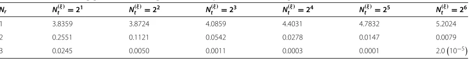
Proceeding in a similar manner as for (38), we pose the general ratio of the relative coding gains achieved by SM, using a variable-amplitude modulation, over a SIMO system using QAM as
lim
wheremust be defined for the desired SM signal
con-stellation size,M(ξ ). The exact ratios as given in Table 1 will vary depending onM(ξ ), but the trend (SM outper-forming SIMO) will remain, as can be seen in Table 2 for
M(ξ )=16, i.e. the values in the last two rows of the tables are smaller than one.
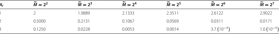
Similarly, using a constant-amplitude modulation scheme such as PSK, we realise that the only difference is that will be unity in (39). Implementing this change means removing the dependence on the signal constella-tion size for SM and resulting in a single table of values for (39), as given in Table 3.
From Tables 1, 2, and 3, we can conclude that a single-input-single-output system using QAM performs better than SM using QAM or PSK, i.e. the values in the first row of each table are greater than 1. These results are applica-ble only to SM which means that at least 1 bit must be sent via the signal-symbol.
SIRξ 1and SINR≈SIRξ(interference-limited scenario) In this case, we neglect the AWGN in the channel and realise that the SIRξ is the dominant term dictating the ABER performance of the system. Looking at the expres-sion for the SIR, we realise that γI is a function of the signal-symbol amplitude for all users and their respective channel attenuations. Thus, we cannot simply extractγI from (34). In particular, in the expression forγI in (11),
Table 1 Relative coding gains of SM using 4-QAM compared to SIMO usingM-QAM
2 0.67 0.38 0.22 0.12 0.068 0.038
3 0.28 0.075 0.021 0.0057 0.0016 4.4(10−4)
interference-limited scenario for SM will be constrained to using a constant-amplitude modulation scheme such as PSK. SM using PSK is shown to perform better than SM using QAM in certain cases [31]. For SM using PSK,
γIPSK≈ α
in the interference-limited scenario. We see that the limit of the ABER tends to (34) with a slight, but very impor-tant distinction: the system reaches an error floor. This is to be expected when the receiver is interference-unaware. IfγIorγIPSKare not large enough, i.e. the channel atten-uations of the various nodes are similar, then this study presents an upper bound for the ABER of the system since (34) still defines the behaviour of the system in the limit. There are three consequences that should be consid-ered similar to the noise-limited scenario analysed above: (i) the system error performance improves when more receive antennas are added at the receiver, (ii) the sys-tem error performance worsens as more SM constellation points are added, as eitherNt(ξ )orM(ξ )is increased and (iii) the detector will fail to decode any data emitted from a node whose desired signal is weaker than the interfer-ing signal. Although analytical work for SM usinterfer-ing QAM becomes intractable, numerical results demonstrate that SM using a variable-amplitude modulation performs in a similar fashion to SM using PSK and leads to the same conclusions. In the remainder of this study, we show that the near–far problem is completely mitigated by applying a jointly optimal ML detector for SM in an interference-limited scenario. In other words, all incoming streams will be decoded and, in particular, the error performance of the system will tend to zero as AWGN approaches zero, despite any interference.
Interference-aware detection
Starting from the system model presented in the “System model” section, the decoded pair (xest,nt)(ξ ),
formed from the estimated symbol xest emitted from
antennanton nodeξ is given by
Similar to the work in the “Interference-unaware detection” section, the union bound technique is used to describe the behaviour of the interference-aware SM detector in the high SNR regions. The main difference between the two detectors comes from the computa-tion of the PEP between the possible received symbols. The union bound for the interference-aware SM detector, which estimates the ABER for nodeξ, can be expressed as
ABERξ ≤ set of all possible symbol-antenna pairings for all nodes, i.e. they independently take values from the set of all pos-sible spatial and signal constellation points, . We define PEPx( ),n( )
t , xˆ( ), nˆ
( )
t
to be the PEP between the
symbolx( )emitted from antennan( )
t being detected as
symbolxˆ( )emitted by antennanˆ( )t .
Table 2 Relative coding gains of SM using 16-QAM compared to SIMO usingM-QAM Nr N(ξ )t =21 N
1 3.8359 3.8724 4.0859 4.4031 4.7832 5.2024
2 0.2551 0.1121 0.0542 0.0278 0.0147 0.0079
Table 3 Relative coding gains of SM using PSK compared to SIMO usingM-QAM
Nr M=22 M=23 M=24 M=25 M=26 M=27
1 2 1.9889 2.1333 2.3511 2.6122 2.9022
2 0.5000 0.2131 0.1067 0.0569 0.0311 0.0171
3 0.1250 0.0228 0.0053 0.0014 3.710−4 1.010−4
Similar to the analytical derivation of (4) in the “Inter ference-unaware detection” section, the ABER for nodeξis shown in (42), where the PEP is given as
A more detailed derivation of (43) is given in the “Derivation of (43)” section in the Appendix. We note that thus far no assumptions have been made as to the chan-nel distribution. Considering Rayleigh fading chanchan-nels for all links in the system, we can derive the closed form solu-tion for EH[PEP(·)] in (42) in the same manner as shown in the “Interference-unaware detection” section with (16) and (17) such that
β = Em
Note that (42) presents an analytical treatment of the most general case of SM using variable amplitude modu-lation for the signal symbol. Given this, the system using the interference-aware detector behaves in a similar fash-ion to the noise-limited system, in that for an arbitrarily high SNR, each user can achieve an arbitrarily low ABER. It should be pointed out that due to the simultaneous detection process, the users with the best SNR will not be able to achieve their single-user-lower-bound (SULB).
The exact effect of the additional nodes/users is fur-ther discussed in the “Simulation results and discussion” section.
Simulation results and discussion
In this section, we aim to show the performance of the interference-unaware and interference-aware detec-tors proposed in (2) and (41). In particular, we aim to show that (41) can successfully decode the incom-ing streams for all nodes. Numerical results demonstrate that (12) and (42) provide tight upper bounds for the ABER of the detectors at high SNR in the interference-limited scenario. Furthermore, we demonstrate that the interference-aware detector for SM performs bet-ter than the ML detector for a multi-user SIMO system using QAM.
The proposed interference-aware detector is jointly optimal for all nodes and does not suffer from the near– far problem, but it needs full channel state information (CSI) from all possible transmitting antennas to each receiving antenna. In addition, finding the optimal solu-tion is an exponentially complex problem. Assuming each
node has the same number of transmit antennas, Nt,
and uses the same signal constellation with M points,
then the interference-aware ML detector proposed has O(MNt)Nu
computational complexity which is proven to be NP-complete [33].
the cost, in terms of RF chains and power consumption would not be. The aim of this study is to characterise the behaviour of SM in the multi-user, interference-limited scenario and compare it to thecomplexity and cost equiv-alent multi-user MIMO system. As discussed in the “Introduction” section and given the complexity expres-sions for the single user MIMO system and the single user SM system, it is apparent that the only validcomplexity and cost equivalentcomparison is to compare multi-user SM with multi-user SIMO. The optimal ML detector for the interference-aware SIMO system hasOM2Nu
computational complexity, where M2 =MNt from the
“SIMO system utilising QAM (noise-limited scenario) ’’ section, making it comparable to the interference-aware SM detector. Recent work on sphere detection algorithms may be used to alleviate this computational cost [9]. Despite the generality of our results, we restrict our simu-lation results to two and three node scenarios for the sake of conciseness.
Simulation setup
A frequency-flat Rayleigh fading channel with no corre-lation between the transmitting antennas and AWGN is
assumed. Perfect CSI is assumed at the receiving node, with no CSI at the transmitter. Only one of the available transmit antennas for each node is active at any transmit-ting instance. In theory, each node independently decides the number of transmit antennas, and, by extension, the signal-symbol modulation it uses. In the simulation each node has the same number of transmit antennas as well as the same spectral efficiency target. In each of the figures, there are three sets of results presented: (i) the simula-tion results for the multi-user detector for each node, denoted by Sim(N(ξ )), (ii) the theoretical results from (12) or (42) for the node of interest and (iii) the SULB,
denoted by SULB(N(ξ )). We define the asymptotically
tight SULB as the system performance in a noise-limited scenario given in (26) which is governed purely by its SNR, defined asEm/No. It should be noted that in Figures 2, 3 and 4 in addition to (26), ASER/2, i.e. (28) divided by 2, is presented and overlaps (26); both are denoted as SULB(N(ξ ))in Figures 2, 3 and 4. This serves to justify the use of (28) in our asymptotic analysis in the “Asymptotic analysis of an interference-unaware detector” section. In addition, (26) is based on the union bound technique and, in some results, SULB(N(ξ )) is above 1, which is
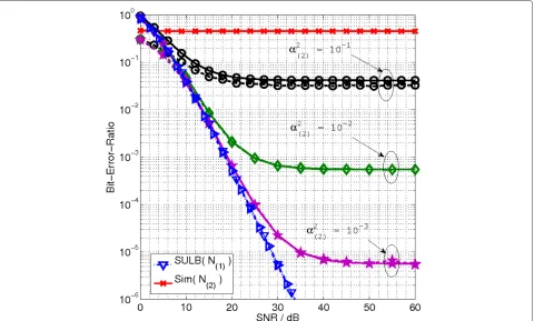
Figure 2Nt(u)=4,Nr=1and a spectral efficiency of 4 bits/s/Hz.ABER for node 1 using the interference-unaware detector withα2(1)=1 and node 2 with a varyingα2
(2). Dashed lines denote simulation results for node 1 while solid lines denote the analytical upper bound. Since the analytical bound is asymptotically tight, at low ABER the dashed and solid lines overlap. Each constant value dashed-dot line with ‘+’ markers corresponds to the asymptote derived in (34) using (40) for the different values ofα2
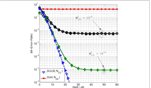
Figure 3Nt(u)=4,Nr=2and a spectral efficiency of 4 bits/s/Hz.ABER for node 1 using the interference-unaware detector withα(21)=1 and node 2 with a varyingα(22). Dashed lines denote simulation results for node 1 while solid lines denote the analytical upper bound. Since the analytical bound is asymptotically tight, at low ABER the dashed and solid lines overlap.
impossible for a real system. In this regard, the SULB is a lower bound on the analytical performance of each sys-tem only at low ABER. To help illustrate the difference in the behaviour of the two detectors, the channel attenua-tions,α(2u), are set in 10-dB intervals. In general,α(2u)may be any real number. Throughout the results, QAM mod-ulation is used for the signal-symbol modmod-ulation in SM with the notable exception of Figure 2, where PSK modu-lation is used to illustrate the accuracy of work done in the “Asymptotic analysis of an interference-unawaredetector” section.
Results for interference-unaware detection
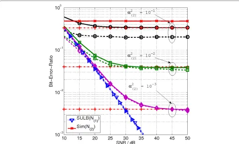
Asymptotic results in the “Asymptotic analysis of an interference-unaware detector” section, in particular (34) using QPSK for the signal-symbol modulation are veri-fied in Figure 2. In this case, is strictly defined by (22). The horizontal lines in Figure 2 represent (34) for varying values ofα(2u)using QPSK modulation. From Figures 3, 4 and 5, where QAM is used for the signal-symbol modu-lation, the developed analytical framework is accurate in all the presented instances. By moving from Figure 3 to Figure 3, where an additional receive antenna is added, the analytical model presented in (12) is a tight upper
bound on the system in the high SINR region. As the chan-nel attenuations for the interfering nodes increase, the detector approaches SULB. Similar to the effects observed in Figures 2 and 3, Figure 4 shows how the tightness of the bound improves as the number of receive antennas increases. In all instances where the interference-unaware detector is used, the node with the strongest SNR dom-inates the detection. The bit streams of all other nodes are not decoded. Since the SINR does not change, all other nodes remain below the effective noise floor at the receiver. This is apparent by looking at the simu-lation results for N(2) and N(3) in Figures 2, 3 and 4. By looking at the presented results, we conclude that (34) tightens as the system approaches its ideal transmis-sion and the mass of the complex Gaussian distributions around each SM constellation point concentrates around the mean. This is achieved by decreasing the interfer-ence in the system or by increasing the number of receive antennas.
Figure 4Nt(u)=4,Nr=3and a spectral efficiency of 4 bits/s/Hz.ABER for node 1 using the interference-unaware detector withα2(1)=1 and node 2 with a varyingα(22). Dashed lines denote simulation results for node 1 while solid lines denote the analytical upper bound. Since the analytical bound is asymptotically tight, at low ABER the dashed and solid lines overlap.
which results in a lower ABER. Comparing Figure 2 with Figure 3 and similarly Figure 3 with Figure 4 where the number of receive antennas is increased in each figure, showing how the addition of a single receive antenna is equivalent to lowering the interference α(2u)
by more than 10 dB. In fact, the effect of each receive antenna is more pronounced as the imbalance between the desired and interfering links increases. By looking at the results forα(22) = 10−2in Figure 2, the results forα2
(2) =10−2in Figure 3, and the results forα(22) =10−2 in Figure 4 at an SNR of 40 dB, we see the error rate of the simulation and analytical prediction moving from 2×10⁻¹in Figure 2, to
4×10⁻³in Figure 3, to 9×10⁻⁵in Figure 4. This ABER decrease shows how the number of receive antennas dominates the performance of SM in general, and par-ticularly in an interference limited scenario. Figure 5 demonstrates that the findings can be extended even in the presence of two interfering nodes.
From the presented results it is clear that when the interference-unaware detector is used, the system ABER plateaus at the derived limits, irrespective of the trans-mit power being used. As discussed in the “Interference-unaware detection” section, and as work in [20] has shown, the ABER improves when the number of transmit
or receive antennas is increased, i.e. the system achieves coding gains.
Results for interference-aware detection
In Figure 6 we see the performance of the jointly optimal interference-aware ML detector for a two user scenario. Figure 6 clearly demonstrates that the analytical model presented in (42) represents an asymptotically tight upper bound for the system in the high SNR region. The node with the worse channel attenuation performs close to its SULB. This is not the case for the node with the better channel.
Figure 5Nt(u)=4, a varyingNrand a spectral efficiency of 4 bits/s/Hz.ABER for node 1 using the interference-unaware detector withα(21)=1, node 2 withα(22)=0.1 and node 3 withα2(3)=0.01. All presented curves are for node 1 unless otherwise stated in the legend. Dashed lines denote simulation results for node 1 while solid lines denote the analytical upper bound. We note that the addition of more receive antennas reduces the ABER and hence closes the gap between the analytical and simulation results.
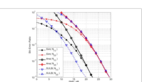
Figure 7Nt(u)=2,Nr=3and a spectral efficiency of 4 bits/s/Hz.ABER using the interference-aware detector for node 1 withα2(1)=1 and node 2 withα2(2)=0.1.Ana( N(u) )denotes the analytical upper bound for nodeu. Since the analytical bound is asymptotically tight, at low ABER the dashed and solid lines overlap.
the interfering signal rather than the background AWGN, which is why the nodes with better channel conditions never perform near their SULB.
The addition of more transmit antennas at each of the nodes results in coding gains for each node as can be seen when Figures 6 and 7 are compared. The reduction in ABER as the number of transmit antennas increases is explained by realising that as the number of transmit antennas increases, the average varianceσz2increases. As
σz2 increases, it leads to a larger Euclidean distance in (10) and (43). The Euclidean distance is increased because there are more cases where the variance is the summation of the individual symbol constellation points, rather than the difference, i.e.n(ξ )t = ˆn(ξ )t occurs less frequently. Effec-tively, more transmit antennas mean that the transmit vectors are spread in a larger Euclidean space. This effect can only be observed when the same spectral efficiency is maintained. In particular, a 2-dB coding gain is appar-ent when comparing Figures 6 and 7 at an ABER of 10−4. However, increasing the number of transmit antennas does not change the relative behaviour of the system, i.e. the SNR difference between the ABER curves of the two nodes remains constant. This behaviour is expected when we consider that (17) is independent ofNtand influenced only byNr.
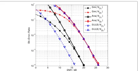
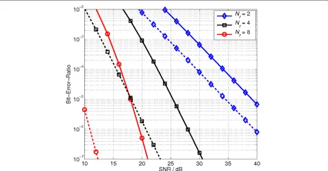
Figure 8 shows the performance of the system when the number of receive antennas is increased. On the one hand, moving from Figures 7 to 8, for a fixed spectral
efficiency and a fixed number of transmit antennas, the addition of more receive antennas results in an increas-ing gap between the analytical ABER curves of the two nodes. In particular, a gap of 4 dB between the
perfor-mance of nodes 1 and 2 with Nr = 2 is increased to
around 7 dB whenNr = 4 and further increased to 9 dB forNr = 8. On the other hand, given that the two nodes experience a channel gain difference of 10 dB, we know that the interference-aware detector cannot reach the per-formance of independent detection and the SULB for the node with the better channel attenuation. Nonethe-less, the gap between their respective ABER curves tends toward the difference between their respective channel attenuation asNrgrows.
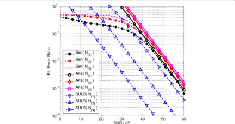
These trends can also be observed if we look at the progression of the ABER curves in Figures 9 and 10. Figures 9 and 10 show the system performance of three users and varying Nr. Similar to the two user scenario, as Nr increases, for the three user case, each user per-forms better and slowly closes the gap to its SULB. As expected, the addition of more nodes increases the inter-ference and pushes the performance of each node further from its SULB, noticeable when comparing Figures 7 and 10 for node 2.
Figure 8Nt(u)=4, a varyingNrand a spectral efficiency of 4 bits/s/Hz.ABER using the interference-aware detector for node 1 withα2(1)=1 and node 2 withα(22)=0.1. Dashed lines denote the performance of node 1 with a varying number of receive antennas while solid lines denote the performance of node 2 with a varying number of receive antennas.
the multi-user SIMO system. Specifically, SM exhibits an approximately 3 dB better performance in terms of
SNR at an ABER of 10−4 for each user. The
rela-tively constant coding gain is the result of the similar detection used for both systems. While multi-user SM and multi-user SIMO may be comparable in terms of detector complexity and the number of transmit and receive RF chains required, each SM node requires mul-tiple transmit antenna elements. The mulmul-tiple transmit antennas mean that the SM constellation points are spread in a larger Euclidean space and thus have lower error probability.
Summary and conclusions
In this study, the performance of SM in the multi-ple access, interference-limited scenario was investigated. Two ML detectors for use with SM were discussed.
The interference-unaware detector was defined and studied in the limit as the SNR approached infinity. Its per-formance over uncorrelated Rayleigh fading channels was studied and a closed form solution for the upper bound of the system was provided. It was shown that this detector inevitably reaches an error floor which is dependent on the system SINR. The exact level was defined as a func-tion and concrete examples were provided. It was shown that the increase in the number of receive antennas has a greater impact on the asymptotic performance of the
system compared to reducing the interference in the sys-tem. The addition of a single receive antenna resulted in greater SNR gains than reducing the interference, α(2u), by more than 10 dB at high SNR. This implies that the number of receive antennas dominates the performance of SM in general, and particularly in an interference-limited scenario.
interference. The impact on the diversity and coding gains further shows the importance of the number of receive antennas in any SM system. A limiting factor, as with all ML detectors, is the complexity. In addi-tion, the receiver must have channel knowledge from all transmitting nodes. These two limitations constrain the application of this detector to the uplink scenario. The interference-aware detector enabled SM to perform better in terms of ABER than the complexity and cost equiva-lent multi-user SIMO system in an interference-limited environment.
This study demonstrated that in order to effectively apply SM in an interference-limited scenario, the number of receive antennas should be maximised. Although more computationally complex than the interference-unaware detector, the interference-aware detector can guarantee that the system does not reach an error floor.
Appendix
Derivation of (32)
We begin by consideringψ:1which corresponds toσz2 =
|x(ξ )|2+ |ˆx(ξ )|2. For this event, we seek to boundσ2
z to two which implies that we should consider
d2+d2ˆgQAM≤2 (46)
where ∈ {(1, 1),(2, 1),(3, 1)} andd are the distances defined in Figure 12 andgQAM= 2(M(ξ )3−1). We introduce
the normalising factor gQAM, given in [32], to maintain
unity power in our constellation. We see that there are only four possible combinations that satisfy (46). In par-ticular
• d2(1,1)+d(21,1)gQAM=0.4, occurs
M(ξ )2/8=32 times,
• d2(1,1)+d(22,1)
gQAM=1.2, occurs
M(ξ )2/4=64 times,
• d2(1,1)+d(23,1)gQAM=2, occurs
M(ξ )2/8=32 times and
• d2(2,1)+d(22,1)
gQAM=2, occurs
M(ξ )2/2=128 times.
We know that these combinations occur for every instance whennt = ˆnt. For a system withNt(ξ ) transmit
antennas, we have
Nt(ξ )
2
unique pairings. This leads to
:
ψ1=
(0.4/2)−Nr32+(1.2/2)−Nr64+32+128 N (ξ ) t
2
.
(47)
Having established the derivation ofψ:1, we turn our
atten-tion to:ψ2which corresponds toσz2= |x(ξ )− ˆx(ξ )|2. If we
look at Figure 12, we see there are additional combina-tions aside from the ones denoted. To this extent, our
Figure 10Nt(u)=4,Nr=3and a spectral efficiency of 4 bits/s/Hz.ABER for node 1 withα(21)=1, node 2 withα2(2)=0.1 and node 3 with α(23)=0.01.Ana( N(u) )denotes the analytical upper bound for nodeu. The analytical bound is again shown to be asymptotically tight at low ABER.
Figure 11Nt(u)=4,Nr=3and a spectral efficiency of 4 bits/s/Hz.ABER of multi-user SM and multi-user SIMO using interference-aware detectors with node 1 experiencing channel attenuation ofα2
bound,σz2 = min{σz2, 2}, serves to simplify the counting and set many of them to 2. In particular, we see that when
σz2 = d2(5,2), thenσz2 > 2. In this case, we boundσz2to 2 and realise thatd(4,2)is the largest distance that we must account for in our expectation analysis. We note that our approach is applicable to larger constellation sizes and, after some careful counting, we see that in general for a given constellation size ofM(ξ )we have that
• d(1,2)occurs a total ofD(1)=4 √
M(ξ )√M(ξ )−1 times,
• d(2,2)occurs a total ofD(2)=4 √
M(ξ )√M(ξ )−2 times,
• d(3,2)occurs a total of
D(3)=4√M(ξ )−1 √M(ξ )−1times and, • d(4,2)occurs a total of
D(4)=8
√
M(ξ )−1 √M(ξ )−2times.
By looking at Figure 12, we can easily see that forM(ξ ) = 16:
• d2(1,2)gQAM=0.4, occurs exactly 48 times, • d2(2,2)gQAM=1.6, occurs exactly 32 times, • d2(3,2)gQAM=0.8, occurs exactly 36 times and • d2(4,2)gQAM=2, occurs exactly 48 times.
We realise that the combinations counted above are appli-cable for every transmit antenna. This implies that we must multiply each count byNt(ξ )which leads to
Figure 12The red squares denote 16-QAM constellation points.
In this image, the constellation is not normalised. The figure shows possible distance combinations between each of the constellation points and their distances to the origin.
:
ψ2=
(0.4/2)−Nr48+(1.6/2)−Nr32 +(1.6/2)−Nr36+48N(ξ )
t .
(48)
To arrive at a final solution, we set all other combination values togQAMas we enforce our bound onσz2giving
Dones =
M(ξ )Nt(ξ )2−M(ξ )2
Nt(ξ )
2
−D(1)+D(2)+D(3)+D(4)2Nt(ξ )
which is the number of elements for which σz2 was set to 2, i.e. σz2/2−Nr =1. We now average and arrive at
. To achieve this, we merely normalise our sum by
M(ξ )Nt(ξ )
2
to account for the number of possible events, resulting in
= ψ:1+:ψ2+Dones M(ξ )N(ξ )
t
2
which when simplified becomes (32).
In Figure 13 we compare the asymptote of SM, given by (34), in the noise-limited scenario forM(ξ ) =16 with and without using (32). Figure 13 exemplifies the accuracy and tightness of our approach.
15 20 25 30
10−7 10−6 10−5 10−4 10−3 10−2
SNR / dB
Bit−Error−Ratio
Simulation Upper Bound
Nr = 2
Nr = 6
Figure 13The dashed lines with circle markers denote the asymptote for the system if the expectation forσz2/2−Nris obtained via simulations.The solid lines with square markers denote the asymptote when (32) is used. Moving from the rightmost to the leftmost pairs of curves, each pair corresponds to an incremental increase inNrfrom 2 to 6. The system is using two
Reaching (38) from (34) with (31) and (37)
Combining (34) with (31) results in
limγI→∞
Restating (37) for convenience, we have
lim Taking the ratio of (49) over (37) gives (38) as
lim
If we consider a Rayleigh fading channel, then we can derive the closed form solution for EH[PEP(·)] in (42) by using ([30], eq. 62). We note that by assuming a Rayleigh fading channel, the argument within (43) can be repre-sented as the summation of 2Nrsquared Gaussian random variables, with zero mean and variance equal to 1, which means that they can be described by a central Chi-squared distribution with 2Nrdegrees of freedom and a probability density function of
The authors declare that they have no competing interests.
Acknowledgements
We gratefully acknowledge the support from the Engineering and Physical Sciences Research Council (EP/G011788/1) in the United Kingdom for this study.
Author details
1Institute for Digital Communications, Joint Research Institute for Signal and Image Processing, School of Engineering, The University of Edinburgh, Edinburgh EH9 3JL, UK.2Laboratory of Signals and Systems (L2S), French National Center for Scientific Research (CNRS), L’Ecole Sup´erieure d’´Electricit´e (SUP´ELEC), University of Paris–Sud XI (UPS), 3 rue Joliot-Curie, 91192 Gif-sur-Yvette (Paris), France.
Received: 26 March 2012 Accepted: 4 September 2012 Published: 19 September 2012
References
1. J Mietzner, R Schober, L Lampe, WH Gerstacker, PA Hoeher, Multiple-antenna techniques for wireless communications—a comprehensive literature survey. IEEE Commun. Surv. Tutor.11(2), pp. 87–105 (2009) 2. R Mesleh, H Haas, Y Lee, S Yun, Interchannel interference avoidance in
MIMO transmission by exploiting spatial information, inProc. of the 16th IEEE International Symposium on Personal, Indoor and Mobile Radio Communications (PIMRC),vol. 1 ((Berlin Germany, 11–14 September 2005), pp. 141–145
3. R Mesleh, H Haas, S Sinanovi´c, CW Ahn, S Yun, Spatial modulation. IEEE Trans. Veh. Technol.57(4), pp. 2228–2241 (2008)
4. N Serafimovski, Di Renzo M, S Sinanovi´c, RY Mesleh, H Haas, Fractional bit encoded spatial modulation (FBE–SM). IEEE Commun. Lett.14(5), pp. 429–431 (2010)
5. A Younis, N Serafimovski, R Mesleh, H Haas, Generalized spatial modulation, inAsilomar Conference on Signals, Systems, and Computers
(Pacific Grove,CA, USA, November 2010)
6. R Mesleh, M Di Renzo, H Haas, PM Grant, Trellis coded spatial modulation. IEEE Trans. Wirel. Commun.9(7), pp. 2349–2361 (2010)
7. A Younis, R Mesleh, H Haas, PM Grant, Reduced complexity sphere decoder for spatial modulation detection receivers, in2010 IEEE Global
Telecommunications Conference (GLOBECOM 2010)(Miami, Florida, USA,
December 2010), pp. 1–5
8. MD Renzo, H Haas, Performance analysis of spatial modulation, in
International ICST Conference on Communications and Networking in China (CHINACOM)(Beijing, China, August 2010, pp. 1–7)
9. A Younis, Renzo M, R Mesleh, H Haas, Sphere decoding for spatial modulation, inProc. of IEEE International Conference on Communications (IEEE ICC 2011)(Kyoto, Japan, 5–9 June 2011), pp. 1–6
10. J Jeganathan, A Ghrayeb, L Szczecinski, Spatial modulation: optimal detection and performance analysis. IEEE Commun. Lett.12(8), pp. 545–547 (2008)
11. SU Hwang, S Jeon, S Lee, J Seo, Soft-output ML detector for spatial modulation OFDM systems. IEICE Electron Exp.6(19), pp. 1426–1431 (2009)
IEEE conference on Sarnoff(IEEE Press, Piscataway, NJ, USA, 2010), pp. 58–63. http://portal.acm.org/citation.cfm?id=1843486.1843498 13. M Di Renzo, H Haas, Improving the performance of Ssace shift keying
(SSK) modulation via opportunistic power allocation IEEE Commun. Lett.
14(6), pp. 500–502 (2010)
14. T Handte, A Muller, J Speidel, BER analysis and optimization of generalized spatial modulation in correlated fading channels, inVehicular Technology Conference Fall (VTC Fall-2009)Anchorage Alaska, USA, IEEE, (September 2009), pp. 1–5
15. MD Renzo, H Haas, Bit error probability of SM-MIMO over generalized fading channels. IEEE Trans. Veh. Technol.61(3), pp. 1124–1144 (2012) 16. E Basar, U Aygolu, E Panayirci, VH Poor, Space-time block coded spatial
modulation. IEEE Trans. Commun.59(3), pp. 823–832 (2011) 17. J Jeganathan, A Ghrayeb, L Szczecinski, A Ceron, Space shift keying
modulation for MIMO channels. IEEE Trans. Wirel. Commun.8(7), pp. 3692–3703 (2009)
18. JN Laneman, DNC Tse, GW Wornell, Cooperative diversity in wireless networks: efficient protocols and outage behavior. IEEE Trans. Inf. Theory.
50(12), pp. 3062–3080 (2004)
19. MO Hasna, M-S Alouini, End-to-end performance of transmission systems with relays over Rayleigh-fading channels. IEEE Trans. Wirel. Commun.
2(6), pp. 1126–1131 (2003)
20. N Serafimovski, S Sinanovic, M Di Renzo, H Haas, Dual-hop spatial modulation (Dh-SM), inProc. of the Vehicular Technology Conference (VTC Spring), Budapest, Hungary, IEEE, 15–18, May 2011), pp. 1–5
21. M Di Renzo, H Haas, On the performance of SSK modulation over multiple-access Rayleigh fading channels, inIEEE Global Telecommunications
Conference (GLOBECOM)(Miami, Florida, USA, December 2010), pp. 1–6
22. M Di Renzo, H Haas, Bit error probability of space-shift keying MIMO over multiple-access independent fading channels. IEEE Trans. Veh. Technol.
60(8), pp. 3694–3711 (2011)
23. J Duplicy, B Badic, R Balraj, R Ghaffar, P Horvth, FKR Knopp, IZ Kovacs, HT Nguyen, D Tandur, G Vivier, MU-MIMO in LTE systems. EURASIP J. Wirel. Commun. Netw.2011, p. 13 (2011)
24. JG Andrews, W Choi, RW Heath Jr, Overcoming interference in spatial multiplexing MIMO cellular networks. IEEE Wirel. Commun. Mag.14(6), pp. 95–104 (2007)
25. D Gesbert, M Kountouris, RW Heath, C byoung Chae, T Salzer, From single user to multiuser communications: shifting the MIMO paradigm. IEEE Signal Process. Mag.24, pp. 36–46 (2007)
26. CW Tan, AR Calderbank, Multiuser detection of alamouti signals. IEEE Trans. Commun.57, pp. 2080–2089 (2009). http://dl.acm.org/citation. cfm?id=1651065.1651094
27. G Auer, V Gianni, I Godor, P Skillermark, M Olsson, M Imran, M Gonzalez, C Desset, O Blume, A Fehske, How much energy is needed to run a wireless network? IEEE Wirel. Commun.11, pp. 40–49 (2011)
28. C Desset, B Debaillie, V Giannini, A Fehske, G Auer, H Holtkamp, W Wajda, D Sabella, F Richter, MJ Gonzalez, H Klessig, I Godor, M Olsson, MA Imran, A Ambrosy, O Blume, Flexible power modeling of LTE base stations, in
IEEE Wireless Communications and Networking Conference (WCNC), (Paris, France, April 2012), pp. 2858–2862
29. S Verdu,Multiuser Detection. (Cambridge University Press, Cambridge, MA), 1998)
30. M-S Alouini, A Goldsmith, A unified approach for calculating error rates of linearly modulated signals over generalized fading channels. IEEE Trans. Commun.47(9), pp. 1324–1334 (1999)
31. M Di Renzo, H Haas, Bit error probability of spatial modulation (SM) MIMO over generalized fading channels. IEEE Trans Veh. Technol.61,
pp. 1124–1144 (2012)
32. MK Simon, M Alouini,Digital Communication over Fading Channels, 2nd edn (John Wiley & Sons, Inc, NEw York, 2005). ISBN: 978-0-471-64953-3 33. S Verdu, Computational complexity of optimum multiuser detection.
Algorithmica.4, pp. 303–312 (1989). doi:10.1007/BF01553893
doi:10.1186/1687-1499-2012-299
Cite this article as:Serafimovskiet al.:Multiple access spatial modulation.
EURASIP Journal on Wireless Communications and Networking20122012:299.
Submit your manuscript to a
journal and benefi t from:
7Convenient online submission
7Rigorous peer review
7Immediate publication on acceptance
7Open access: articles freely available online
7High visibility within the fi eld
7Retaining the copyright to your article