R E S E A R C H
Open Access
A novel scheduling framework for QoS-aware
OFDMA resource allocation in a network with
small relay cells and macro users
Venkatkumar Venkatasubramanian
*and Thomas Haustein
Abstract
Relaying is a convenient way to provide full coverage in cellular networks. In particular, small relay cells can be used as a cost-effective solution for indoor coverage in MIMO–OFDM systems. The small relay cells would need to cater for indoor users’ quality of service (QoS) expectations. One key QoS objective is delivering stable data rates for multimedia applications, which we refer to as guaranteed data rates. In this article, we consider optimization for delivering guaranteed data rates in a network with multiple relays and a macro base station, in a scenario when there are both macro users and relay users to be served. A novel scheme called cell-guaranteed bit rate by relay scheduling is proposed, with both optimal and heuristic scheduling methods. To perform the optimization we exploit resource block allocation, and parameters such as relaying duration and relay bandwidth allocation. Interference between relays and macro is avoided through time domain orthogonalization. Another key aspect of the scheme is inter-frame scheduling, wherein relay feeder links can be flexibly scheduled in any time slot along with macro users. Performance evaluation is presented using real-time indoor measurement channels and a sample test scenario. Results show the heuristic method can improve performance by 89.47% as compared to round-robin scheduling at relays and is within a 5% gap to optimal scheduling.
Introduction
The idea of relaying has attracted high interest over the last decade as a solution for improving coverage in cel-lular networks. One way to realize relay-based solutions is through installation of dedicated ‘helper’ nodes, which are also known as fixed relays or infrastructure relays. For example, in the literature, the studies [1,2] discuss some practical deployment scenarios and methods such as time division multiple access, frequency division multiple access (FDMA), in-band relaying and out-of-band relaying for fixed relays.
Fixed relays have traditionally been deployed in cellular networks as repeaters; a device which re-transmits after boosting the signal. The repeaters are installed by a service provider and their transmission parameters are set to ful-fill the network needs and standardization requirements. Such devices have been a part of the coverage solution for both global systems for mobile communications (GSM)
*Correspondence: [email protected]
Wireless Networks, Fraunhofer HHI, Einstenufer 37, 10587 Berlin, Germany
and wideband-code division multiple access systems, for example, as evaluated in [3].
The new generation of cellular technologies such as Worldwide Interoperability for Microwave Access (WiMAX), or long-term evolution (LTE) use orthogo-nal frequency division multiplexing access (OFDMA) as the air interface. At Fraunhofer Heinrich Hertz Institute (HHI) we have developed an LTE test-bed to demonstrate the features of LTE, showing capabilities such as peak downlink data rate of 160 Mbps using 2×2 multiple input multiple output (MIMO) over 20 MHz bandwidth [4].
Recent indoor LTE measurements have shown the prob-lem of so-called coverage holes in macro cells at 2.6 GHz [5]. These are areas in the cell which receive markedly low signal power. It has been observed that attenua-tion from obstacles in urban environment can add to pathloss attenuation at 2.6 GHz, and thereby limit outdoor to indoor coverage. For example, building penetration loss and modern window coatings originally designed for ther-mal insulation add to the mean pathloss at 2.6 GHz. Field trials with indoor relays showed that very good coverage can be obtained from MIMO–OFDM air interface.
Indoor relays become important to future cellular net-work for the following reasons. First, some recent statis-tics have shown that indoor users originate 60–90% of the cellular traffic [6,7]. Thus, indoor coverage solutions are important. Second, high targets for indoor cover-age have been set by International Telecommunications Union (ITU) by requiring an average cell spectral effi-ciency of 3 bits/s/Hz/cell and user spectral effieffi-ciency of 0.1 bits/s/Hz/cell indoors for fourth generation systems (4G) [8]. LTE-advanced [9] has been working on indoor coverage solutions to meet the target. Third, relays are a convenient way to realize indoor small cell solutions because installation of expensive cables are not necessary. Deployment of advanced relaying by data regeneration, also known as decode and forward (DF), is under discus-sion by 3GPP, classified as types 1 and 2 relays. System-level investigations with DF relays for OFDM cells in [10] showed a 3-dB power gain for indoor users. Improve-ment in minimum data rate based on Shannon capacity formula has been shown based on the channel sounding measurements in 5 GHz from an indoor relay in [11].
In this article, we propose an approach for improv-ing the performance of DF in-band multi-antenna relays through resource optimization. Our main resource opti-mization tool is diversity in channels across frequency subcarriers and multiple users. The process of utilizing this diversity at relays is called scheduling at relays. In the spirit of this approach, we conducted indoor field tri-als at 2.6 GHz and full 20 MHz bandwidth using multiple antenna relays (MIMO relays) to characterize the indoor channel frequency response. We also performed data rate evaluation based on channel quality feedback in frequency division duplexing (FDD) operation and interference-free scenario.
Prior works and contributions
Among related works in scheduling-based relaying, the literary works [12,13] propose fairness approaches to OFDMA relaying assuming multiple parallely activated relays in a time slot. A similar architectural assumption is used in this article, thereby enabling spatial frequency reuse among many relays within a macro-cell. For relay-ing without spatial reuse, we refer to works such as [14], which performs optimization by enforcing that only one relay link is active on a subcarrier in the entire macro-cell. The authors of [12] propose resource partitioning of feeder links based on time slots by considering that the relays transmit concurrently in one time slot. They further optimize the time slot splits between relay feeder links to improve relaying efficiency, without dealing with user scheduling issues at relay access links. The study in [13] proposes a relay scheduler called multiple relay parallel activation, in a framework similar to [12] but wherein they make use of user-subcarrier scheduling at each relay. The
scheduler however does not optimize relaying time dura-tions. More importantly, their scheduler tries to minimize the outage ofallthe active users and thus also does not exploit admission control procedures.
Our objective in relaying is to maximize the number of users who are given guaranteed bit rates (GBR). This approach is applicable to a real-time mode called GBR in LTE which allows for an admission control method to be employed.
In [15], we proposed a novel scheme called GBRS for the case of relay GBR users. GBRS protocol maximizes the guaranteed bit rates offered in an LTE cell based on joint user scheduling, relay access time optimization, relay spatial reuse, and admission control. Admission control is performed hierarchically also taking the feeder link efficiencies into account.
In this study, we go a step further and deal with a situ-ation which will be often encountered at the system level; there are both macro and relay GBR users to be served in a cell. We provide a novel approach to improve per-formance in this challenging situation by building on the GBRS protocol and term this cell-guaranteed bit rate by relay scheduling (cell-GBRS).
The novel ideas behind our cell-GBRS algorithm which we present in this article are (a) decoupling resource allocation problems for relays and base station and (b) inter-frame scheduling. Inter-frame scheduling denotes the approach of flexible resource partitioning, wherein the scheduling of macro-base station users can be inter-spersed in dedicated relay time slots. Similarly, the base station opportunistically activates feeder link to the relays in few subcarriers within the macro-users frames. This possibility of interspersing relay and macro users is already made use of in [13]. However, fairness between the macro users and sets of relay users is an issue which needs further attention. In our cell-GBRS scheduler, we address this issue and provide a fairness-based framework for sup-porting the relay and macro users. In our framework, we use independent sub-schedulers in dedicated frames; one for the macro-users and one for each relay set and use inter-frame scheduling to connect the sub-schedulers. Through detailed description of the algorithm, we show how to best utilize the network resources through our scheduling framework.
node placement settings and thus predict the system per-formance in terms of number of supported users.
As a suitable illustration, “Example numerical results” section presents simulation-based results for a single-cell scenario considering 1 Mbps bit rate per user. For pre-senting these results, we use quantized 26 modulation and coding levels per frequency resource block, which has been adopted for WINNER studies [16].
One attractive feature of our relaying solution is how-ever that any MCS feedback scheme can be applied. This means that the relaying and macro-cell algorithms need not be re-worked for a change in MCS feedback lev-els. For instance, as a response to uplink congestion, the MCS feedback level can be reduced to either coarse, fine, or extended feedback scheme, as we presented in [5]. Results show that our relaying scheme is robust to reduc-tion of uplink feedback. A 91.7% reducreduc-tion using extended feedback scheme results in only 5% performance loss.
We compare our results with a baseline synchronous round-robin relaying scheme based on [12]. Results show improvement of 89.47% as compared to the baseline scheduler.
The article is organized as follows. In “Relay deploy-ment” section, the scenario for relaying is discussed. In “Scheduling framework in a cell” section, the framework of relaying and optimization is described. In “Problem definition” section, the problem statement is given. In “Scheduling steps” section, the detailed steps of the pro-posed cell-GBRS scheduler is provided. “Channel mea-surement study” section presents the indoor channel measurements which are used for our results. In “Example numerical results” section, we illustrate the performance benefit of our scheduler through simulations in an exam-ple test scenario.
Relay deployment
We consider the downlink of a large macro-cell com-prising a macro base station and few relay transmitters. There are indoor users located in the cell in many residen-tial/office buildings, and only few buildings are equipped with the relays. Thus, the cell has to cater a mixed sce-nario of direct and relayed transmissions. The users who are catered directly by the base station are called macro-users, and the users who depend on a relay are called relay users. The large macro-cell has dimensions in the order of hundreds of meters.
The relays are DF relays, in which case a relay fully decodes the data from the base station before forwarding to the users. The relay applies uniform transmit power on all subcarriers, schedules the users on selected resource blocks, applies modulation and coding scheme (MCS) and re-transmits on the access link. A user is assumed to be given handover to the relay only if the received sig-nal power (RSRP) from the relay is satisfactory. The data
transfer from the macro base station to the relay is done on the same air interface, which is called in-band relay-ing. The coverage area of a relay is relatively smaller than a macrocell and is called a relay cell. We do not differ-entiate between type 1 and type 2 relays [17], or other signaling requirements but rather focus on the data rate improvement that is achievable through deployment of relays.
The relay can be placed at a convenient location indoors, a deployment which is similar to a Wifi access point. The relay unit consists of two parts: a feeder unit which con-nects to the macro base station and an access unit which connects to the user equipment. All transmitters and receivers are equipped with multiple antennas, thus pro-viding 2×2 MIMO–OFDM air interface on three separate links: (a) the direct link from base station to macro-users, (b) the feeder link from base station to relay feeder unit, and (c) the access links from relays access unit to relay users. The access and feeder links of a particular user can be on different set of frequency sub-carriers.
Scheduling framework in a cell
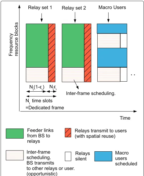
The purpose of scheduling in OFDM cells is to ensure that the radio resources are utilized both efficiently and with some fairness. Our proposed scheduling framework in a macro cell consists of two aspects: relay scheduling and user scheduling. Relay scheduling concerns which set of relay nodes would transmit in a time slot. User schedul-ing deals with schedulschedul-ing macro users and relay users on resource blocks in a time slot. To incorporate the above two aspects of scheduling, we consider a dedicated frame structure as in Figure 1.
In this frame demarcation Nt time slots make a
so-called dedicated frame. A certain set of relays and users of those relays are served in each dedicated frame. Figure 1 shows an example of three dedicated frames, one for users of relay set 1, one for relay set 2 users, and one for macro-users. The introduction of dedicated frames pro-vides fairness by pre-allocating equal number of resources to each relay set and macro-users. This notion of fair-ness thus avoids only few relay cells from consuming the system bandwidth. There are two types of time divisions.
• Frame splits: frame splits are parameterized to be the time durations for which each of the dedicated frames transmit out of the total time. A dedicated framet is thus assumed to transmit forNttime slots (0.5 ms
each time slot). The configuration of the frame split ratios will depend on the system level fairness targeted for different sets of users. For example, factors such as whether the macro-users are prioritized over the relay users may influence the frame splits.
Figure 1Time frame structure for relay scheduling.The figure shows frame demarcation and other framework assumptions. For example, three dedicated time frames which are assigned for the users of two relay sets and a macro base station are shown. Feeder link data are sent from the macro base station to the relays for in-band relaying. Inter-frame scheduling refers to the opportunistic assignment of any free bandwidth in a frame to another link.
link are active out of theNttime slots. The relay time
splits are denoted using an optimization variabler,
refer Figure 1, such that the relay receives for N(1−r)time slots and transmits forN(r)time slots out ofN time slots.
The other physical layer aspects in the proposed frame-work are as follows.
• Full frequency reuse: The main idea of our relaying solution is to let each relay utilize the full
transmission bandwidth, which we term full frequency reuse. In our viewpoint, the major benefit of this approach is the spectral efficiency gain that is achievable from multi-user diversity and frequency diversity on the relay access link. This gain can provide better network performance via appropriate user scheduling algorithms, and can be exploited at all the relays and the macro base station. Therefore, the relay feeder link and access link are split into time phases (as shown in Figure 1) instead of frequency division. One important feature is that the access and feeder links of a particular user can be on different set
of frequency sub-carriers which provides a high degree of freedom for scheduling.
• Interference coordination: A cellular network may consist of a number of relays deployed for specific cov-erage needs. One example is installation of relays in an office building consisting of many floors, wherein a relay is deployed on each floor. All the relays may then utilize the same licensed frequency band for access links. Thus, interference situations may arise if the relays are closely placed or if users of one relay move to another relay cell. Interference coordination is then necessary. This coordination is handled according to the frame structure in Figure 1 by scheduling different sets of relays in each time slot. To do this, a set of non-interfering relays is defined as a relay set. Thus, a relay is first included in a relay set and then the relay set is scheduled on a time slot. This means that potentially interfering relays are orthogonalized by being scheduled on different time slots. At the same time, care should be taken to avoid possible relay to macro-user interference. Therefore, we enforce that the relay transmitters are silent during the dedicated frames (time slots) assigned to macro-users.
• Spatial reuse: In reality not all the relays would actually interfere with each other. The transmission power of relays is low (typically 23 dBm) which means that the relay cell sizes are also relatively smaller. Thus, multiple relays may be able to transmit within a large macro-cell without causing interference to each other if they are sufficiently separated. Therefore, non-interfering relays can be scheduled simultaneously which we term spatial reuse. • Inter-frame scheduling: Users in a large cell
are associated with either a nearby relay or directly to the macro-base station. For overall fairness, time slot splits are fixed among dedicated frames, i.e., between each relay set (and its set of users) and macro base station. The fixed demarcation of time slots may however result in under-utilization of resources in case there are not enough active users in one or more time frames. To overcome this problem, we propose inter-frame scheduling, wherein free bandwidth from one dedicated frame is temporarily re-assigned to another frame and to the link which can best utilize it. Inter-frame scheduling process is explained in detail in “Inter-frame scheduling” section.
Problem definition
Summary of variables and constants
The following are the list of constants and variables. Constants:
• M: The maximum number of resource blocks in the downlink for a macro-cell assumed to be available in a time slot.
• Q: The total number of dedicated frames. • ukm: The modulation and coding value formth
resource block and thek th user to achieve a target bit error rate. These are obtained from the channel estimation in the downlink. It is represented in loaded bits per subcarrier on an OFDM symbol (data symbol) and applied throughout that resource block. • L,T:L is the number of data subcarriers per OFDM
symbol in the downlink for a macro-cell.T is the number of OFDM symbols per time slot. The productL×Tis for example 144 data symbols. The productL×T×ukmwill give the bits loaded per
resource block.
• Nt: The total number of time slots in a dedicated
frame. We drop the suffixtfor convenience and just call thisN. Each dedicated frame consists of time slot splits for feeder and relay transmissions.
• R,Rt: The total number of relays in the macro-cell
and the total number of relays in framet, respectively. • RtU: The set of relays in the macro-cell in a framet. • γr: The spectral efficiency (averaged over all the
subcarriers) of the feeder link from base station to the rth relay. It is assumed that this spectral efficiency can be realized by coding the feeder link data symbols across few randomly distributed subcarriers in the frequency domain.
• K,Kr,KM:K is the total number of active users,Kris
the number of users affiliated to therth relay.KMis
the number of macro-users affiliated directly to the macro base station.
• Fr: Feasible set of users at therth relay.
• Ur,UM,Ut:Uris the set of users affiliated to therth
relay.UMis the set of macro-users indices affiliated
directly to the macro base station.Utis the set of all
users affiliated to thetth dedicated frame at the start of scheduling.
Variables:
• ak: Binary variable to model data rate satisfaction of
userk.akequals 1 if data ratekhas been assigned
and equals zero if data rate is less thank. • xkm: Allocation variables showing the amount of
allocation ofmth resource block to the k th user in the relay to user access link.0≤xkm≤1.
• br: Bandwidth allocation variables allocated to therth
relay’s feeder link borrowed from the frames other than the current onet.br ≥0.
• ˆr: Bandwidth allocation variables in terms of
resource blocks allocated to therth relay’s feeder link during the current framet.0≤ ˆr ≤M.
• k: Duplex time sharing variables showing the time allocation to thekth users access link. This is normalized toN, are thus fractions0≤k ≤1. It
takes the value 1 for macro-users.
• r: Duplex time sharing variables showing the time
allocation to therrelay to transmit. This is
normalized toN, and are thus fractions0≤r≤1. • MS: Surplus bandwidth resources available for
inter-frame scheduling.
The overall cell objective is to satisfy the maximum number of users for each dedicated framet
max
k
ak (1)
∀k∈Ut
For achieving (1) there are however various radio resource constraints as we would observe in the following sections. The detailed steps of the macro-user and relay scheduling phases are presented in the following sections.
Scheduling steps User connection
In the first step, each user indicates the preferred trans-mitter for connection (which relay or macro) and is affili-ated to that node. This step of user association can simply be performed based on the well-known key performance indicators, e.g., signal-to-interference-noise ratio (SNR) or RSRP. We assume that a user connects either to the closest relay or macro-base station within its coverage zone.
Relay grouping
In the second step, the relay transmitter nodes are grouped into different sets. Each relay set transmits on its corresponding dedicated frame. This grouping of trans-mitters is based on the condition of realizing very low interference mutually and in practice can be done in two ways. The first way is static, wherein the global position-ing system coordinates of the transmitters can be used to work out the inter-transmitter distance and thereby find the relays which are sufficiently out of range. The sec-ond and more robust way is dynamic, wherein a central controller or the base station obtains interference reports from the users of each respective relay. Thereafter any two relays(r1,r2)are decided to be mutually non-interfering only if all the users ofr1report very low interference from r2and vice versa. We provide a simple algorithm called SUFFICIENTGROUPING which can be applied for the case of interference reports.
• For each relayr inSET, obtain interference reports from its users which contains the ids of interfering relays. By using all interference reports at all relays, minimum number of sets of mutually non-interfering relays are to be obtained. This is done as follows. • Start with relayr=1and incrementally add mutually
non-interfering relays to the set. Call this as interference setI1. Thus no two relays inI1are interfering each other. Proceed to the next relay not inI1, obtain mutually non-interfering relays and name the setI2. Continue the process until there are no more relays left. Thus inQiterations, we haveQ sets of mutually non-interfering relays, each being a subset ofSET.
• Now obtain the minimum number of sets out ofQ such that all the relays are covered. This is a standard set cover problem that can be solved through a greedy heuristic [18]. As a result we would haveQ−1sets. • Perform the following sequentially for relaysr=1to
R. If a relayr is in more than one subset, keep it only in the set with the minimum number of relays. This step ensures that relayr is not feeder link throughput constrained and also that we prevent a relay from transmitting twice inQ−1frames. Remove it from all the other subsets. Ties are broken randomly.
At the end of the grouping algorithm, we would thus have Q − 1 relay sets and one macro-base station, which are scheduled inQdedicated frames. Now receiver scheduling is done in two phases: (a) phase 1 for dedicated frames, consisting of macro and relay users and (b) phase 2 for inter-frame scheduling.
Macro dedicated frames
The macro dedicated frames are frames in which macro-users are scheduled for reception. In this section, we describe the scheduler for macro user selection and resource block allocation. In this step, resource block scheduling is done for the direct link from the macro base station to the macro-users without allocating any resource blocks to the relay feeder link.
The objective function for macro scheduling is framed as
This above multi-objective has been formulated intu-itively keeping in mind the possibility of resource shortage in other frames for feeder links. The first objective max-imizes as many user guarantees as possible which is the
key performance indicator. The second objective mini-mizes the bandwidth consumed for the direct link users while providing those data rates. For example, satisfying four users instead of just three is a better resource alloca-tion as per the first objective, whereas satisfying those four users with minimal bandwidth is the target of the second objective. For convenience, we call the first objective as MAXUSER and second objective as MINBANDWIDTH.
We note that we have intentionally not formulated sum-rate maximization or proportional fairness as the second objective. The effect of (2) is that the macro scheduler is expected to free as many additional resources as possible for the relay feeder links in other frames.
Optimally solving the dual-objectives in (2) can be done sequentially via two linear programs (after relaxing the variables to be continuous) using solvers such as LIPSOL [19]. The MAXUSER problem can be solved first as a lin-ear program to obtain the feasible set of users, and then solve the MINBANDWIDTH problem as another linear program for the feasible set of users. It may however be too complex to be beneficial in real time as it involves solving two linear programs.
Sort and greed scheduler
We now present a simple heuristic algorithm called ‘Sort and greed’ for scheduling macro users towards the objec-tives in (2). We solve the problem iteratively as follows.
• Start with a user setUMwhich is the full set of macro
users and a set of resource blocksVM = {1,. . .,M}.
Perform the following iterations to solve for
(k∗,xk∗m∗)and updateUMandVM.
Equations (4)–(6) can be solved as a simple greedy selection of resource blocks for userk∗. Hence, the name ‘sort and greed’.
• The userk∗and its corresponding set of allocated resource blocks are removed fromUMandVM,
respectively, after each iteration. Proceed to iteration n+1. The method continues until eitherUMorVM
is empty.
Scheduling algorithm at relays
In-band relay problem
We begin by describing the problem for a relay in dedi-cated framet. It can be recollected that many relays can be expected to be co-scheduled in the same frame. The objective of maximizing the number of satisfied users for the relaying case is written as
max
In (8),k denotes the fraction of time slots for which the relay access link to user k is active out of the total N time slots. This time splitting on a user-subcarrier basis denotes aper user half-duplex operation. This half-duplex functioning however might require tight filtering and isolation requirements at relay feeder unit to avoid inter-carrier interference.
A more practical approach is a per relay half-duplex operation. In this case, we require that when the access link of a relay r is activated, the feeder link altogether stops to that relayr. Because of thisper relay half-duplex operation, the variablesk are now replaced byper relay half-duplexvariablesr. A spectral efficiency ofγr aver-aged over all the subcarriers is assumed for the feeder link to relayr. The assumption of average spectral efficiency means that the subcarriers comprising a resource block allocated to that relay are randomly distributed in fre-quency domain. We point out that a practical mechanism for distributed subcarrier resource allocation to a relay is available through resource allocation type 2 in LTE [20].
The relay may borrow bandwidth br from all other
dedicated frames which have a surplus. Thus, we have
Nˆrγr(1−r)+Nγrbr =Nr
where (11) says that amount of feeder link data is equal to the amount of access link data forrth relay. This gives the half-duplex time sharing values
The set of equations (7)–(10) can be relaxed using con-tinuous variablesak. Following the relaxation, it can be
transformed using weights −k1 as we showed in [21]. Upon plugging the value ofrfrom (12) into this relaxed
objective, we get the following set of equations for a given set of relaysRUt in framet:
where the mapping functionH(k) uniquely maps a user indexkto a relayr.
The solution to the problem requires solving: resource allocation variables at relays xkm, bandwidth allocation
variables in current dedicated slots ˆr, and bandwidth
allocation variables of surplusbr.
Straightaway we note that the variablesbrmultiply with xkm, which means that they cannot be re-written in a
lin-ear form. We thus use a slight work around and assume that the feeder link active duration to a particular relay does not vary w.r.t the frame number of the dedicated frame.
The above assumption changes (11) into
Nˆrγr(1−r)+Nγrbr(1−r)=Nr
From hereon, one could simply substitute the summa-tion of variablesˆr+bras a new variablerwhich has a
new upper boundM+MS.
Now we just need to solve resource allocation variables xkmand bandwidth allocation variablesr. Can (13)–(19)
be solved iteratively? The answer is no. The reasoning is as follows. In iterationn, let variablesxkm are solved by
treatingras constants. Assume that for a userkin relay
cellr, the data rate inequality in (14) is met with equality. In iterationn+1 because of the constraint in (14) for user k,r cannot be increased further. Thus, for all the other
To solve the problem with low complexity, our basic idea is to decouple the two problems. Importantly, we note that if the data rates are feasible in therth relay’s access link (to its users), there exists a corresponding solutionr>0
for which it is also feasible in the end-to-end link. The converse part is also true: if the data rates are not feasi-ble in the relay’s access link, there does not exist a solution
r >0. Based on this fact, we use the notion of a feasible
list to decouple the problem. A feasible listFris defined as
the subset of users in a relay cellrfor which a scheduling solution for data ratesk,∀k∈Frexists in the access link.
Thus,LTmxkmukm ≥ k,∀k ∈ Fr. Now the
schedul-ing problem at relays is to minimize the feeder bandwidth that would be needed for a feasible user list. This schedul-ing problem is solved in relay resource allocation (RRA) subroutine. We thus have the following stages.
• Solvexkm,∀k∈Fr,∀r,∀mwith an objective to
minimize the feeder bandwidthrfor relayr while
guaranteeing data rate demandk ∀k∈Fr. This is
called the RRA sub-routine.
• Select the best set of feasible lists across all the relay cells{1, 2, 3,. . .,R}such that the sum of feeder bandwidths does not exceedM+MSin (18). This is
called the group selection (GS) sub-routine. • The value ofMSis not known initially to the
scheduler. In view of this, the group-selection subroutine is first done for each individual dedicated frame considering a feeder bandwidth limit ofM. Upon implementing this phase on all theQ frames, the surplus resource valueMSis obtained.
• Finally, the inter-frame phase is realized, wherein the group selection is repeated again on the surplus resourcesMSfor all the links with resource shortage.
RRA subroutine
In the RRA subroutine, the objective is to minimize the required feeder bandwidth for a feasible listFr. Implicitly,
we thus enforce xkm = 0, ∀k ∈/ Fr,∀m. The
prob-lem is now essentially to minimize the maximum of the feeder bandwidths computed for each user in Fr. Thus,
we deduce for each userk∈Fr, the feeder bandwidthkr
required to realize an end-to-end rate ofk. This
band-widthkris the critical bandwidth, which is the bandwidth required to include userkin the feasible setFr. Equating LTrmukmxkm=k∀k∈Fr, and usingrfrom (21),
To minimize the feeder bandwidth needed by the setFr,
we are required to minimize the maximum taken over the set of users in listFrfor each relayras
From the above, we may now represent the problem for the relay cellrand given a listFrsimply as
max
This type of problem as in (24)–(26) is a frac-tional linear program [22] in variables xkm. The
opti-mal solution is obtained by using substitutions z = [mk∈Frxkmukm]−1andykm = xkmz, which basically
transforms the fractional problem into a standard linear program as follows by usingtas a dummy variable:
maxt (27)
Equations (29) and (30) are written from (25) and (26), respectively. Equation (31) appears because of the substi-tutions. The solution for (28)–(31) can be obtained using linear programming solvers such as LIPSOL [19]. How-ever, it can computationally be expensive for real-time implementation.
Sub-optimal method
We now present a simplified algorithm for relay resource allocation subroutine that can be implemented with less complexity. This sub-optimal scheme is called Heuristic– GBRS.
• Step 1: First, we ascertain if an admission listAr ⊂Kris
a feasible list. The requirement is to obtain a feasibility certificate via scheduling but with low complexity. For this we perform an external point descent as follows. • Step 1.1: Sum rate maximization: Greedy resource
allocation is performed to allocate the resource blocks to users with highest spectral efficiency. On a per resource block basis, this is done as
k∗=arg max
k ukm, ∀m (32)
From (32) we basically obtain initial binary solu-tions ofxkm asxk∗m = 1 ∀mandxkm = 0 ∀k = k∗,∀m.
xkmin Step 1.1 satisfy the targeted data rates andG2, the set of users for who the solutions does not pro-vide the data rate. Thus, some resource blocks are de-allocated from users inG1and allocated toG2. • Step 1.3: Resource block reallocation: A set of
resource blocksVare pooled and is considered trans-ferable fromG1toG2. The poolVis formed such that none of the bit rate targets of the user setG1would be sacrificed if any one resource block in the pool was removed.
• Step 1.4: User selection: A user is prioritized based on
˜
The metric in (33) exploits user diversity by doing user selection on the basis of average channel qual-ity and the rate demand. To benefit from frequency diversity, we assign a resource block tok˜on the basis of spectral efficiency as
m∗=arg max
m∈Vukm˜ . (34)
Updatexkm˜ ∗ = 1, andxkm∗ = 0 ∀k = ˜k. The
resource blockm∗is removed from the setV. Steps 2 to 5 are repeated until (a) all users are given their bit rates, or (b) the resource block set V is empty. Compute the total allocated data rates to the listAr
asmukm, ∀k∈Kr.
• Step 2: If the listAr was found to be infeasible, this
list is ignored, we go back to Step 1 and consider another admission list. If the admission list is feasible, we proceed further. In this case, we compute the feeder bandwidth required for each user inAr based on (22).
The computed feeder bandwidths is stored in a list ‘BW’. • Step 3: We now employ scheduling once more to min-imize the maximum bandwidth in BW. To do this, resource blocks are reassigned from a userkmin, who requires the least bandwidth in the listBW to a user kmax who requires the highest bandwidth. The pool of resource blocks allocated withkminis denotedVmin. To exploit frequency diversity, we select the best resource block usingm∗ = arg maxm∈Vminukmaxm. Further, for
a more precise computation, the resource block m∗ may be subdivided intoggranular blocks and optimum number of granular blocks are reassigned from m∗. Steps 2, 3 are repeated until maxBW −minBW < δ, whereδis sufficiently low.
Group selection subroutine
This subroutine is used at the base station to allocation the feeder bandwidths to relays. The problem is to decide the best group of feasible user subsets from all the relays in that dedicated frame. Let us denote byFri, theith feasible
list in a relay cellr. Now the best group of user lists in all theRrelay cells, out of all feasible listsFri,∀i,∀rhas to be found. Let the minimum feeder bandwidth solution of the RRA subroutine to a listFi
r bemin(i,r). By using binary
variablessirto indicate the choice ofFri, we now write the
following objective
Equations (35)–(38) are the integer program for which optimal solutions can be found by standard techniques. We however propose to use a sub-optimal gradient scheme. In each step of the ascent, we merely select the ‘user list-relay’ pair (i∗,r∗) with the minimum gradient
min(i,r)
|Fri| , ∀i,∀r and set si
∗r∗ = 1. The algorithm
termi-nates whenirsirmin(i,r)=Mor if all the lists have
been exhausted. Upon resolvingsir,∀i,∀r, the feeder link
bandwidth to a relayris obtained as
r = these lists, the RRA subroutine has to be implemented and the feeder bandwidth has to be informed to the base sta-tion. Conveying this information to the base station can be bandwidth expensive.
To reduce complexity and the signaling overhead, we again propose to sort the users using an admission control metric
mukm
k at each relay. This metric thus takes into
account the MCS values of the access link in terms of bits per subcarrier and the data rate demand from the user. The firstiusers of the ordered list in relay cellrmake the ith admission list. If it is a feasible list, the same is denoted asFri. Note that there areKrusers and thusi=1,. . .,Kr.
This effectively means that each relay cell now only needs to feedbackKr values of feeder bandwidth request,
i.e., informmin(i,r), for i = {1, 2, 3,. . .,Kr}. The base
station applies the group selection subroutine and decides the best valuei = i∗for each relay. This is in fact a hier-archical implementation of admission control: each relay makesKr admission lists and informs the corresponding Kr feeder bandwidth requests to the base station while
andFri∗, we simply back substitute in (12) and obtain the optimal durationrfor relayr.
Inter-frame scheduling
Following the scheduling phase of dedicated frames, the next phase of scheduling is called inter-frame schedul-ing. Inter-frame scheduling works in the following ways: an available resource from one frame is opportunistically assigned to either (a) a relay feeder link, or (b) macro-users. The important point is that after the dedicated scheduling phase, we are now aware of the dedicated frames on which all the users are satisfied and the amount of bandwidth resources that are available. These frames are called frames with surplus. There may be thusMS
‘sur-plus resources’ available from all the frames (there may be some leftover resources even in frames without surplus).
The task of scheduling is now to best allocate theMS
bandwidth units to relay feeder links and macro user links. To do this we can again implement the group-selection subroutine, usingMS as the bandwidth limit. The group
selection subroutine would simply refer to the already computed RRA subroutine results to deduce the band-width needed to support extra users. However, this proce-dure might incur higher complexity in case there are large number of relay sets. To cut down complexity, an incre-mental mechanism is used as follows. In this mechanism, in each iteration at most one extra user is added from each relay cell. The bandwidth request to support that one extra user from each relay cell is known from the RRA subroutine computation. In a current iteration, the users are selected by sorting the bandwidth requests and then choosing the minimum bandwidth request. The iterations continue until there are no more users or bandwidth left.
In practice, it might be needed that the feeder data to a relay arrives ahead of its access link getting activated. To handle this, we propose a simple feeder accumula-tion schedule wherein all the frames with surplus are scheduled ahead of the frames with deficit.
Interference situations
We adopt time domain orthogonalization technique to handle the following interference situations.
Relay to relay
In the notion of inter-frame scheduling, feeder data may be sent to one or more relays in a frame which is meant for another set of relays. Thus, the access link of a nearby relay may be active while the feeder data are being sent. This will cause interference on the feeder link. To han-dle this case, we apply time domain orthogonalization and thus limit the time duration of inter-frame feeder link toNt−maxr∈RtrNt. This essentially means that we
switch off the feeder link when any relay of that frame starts its transmission. The feeder link data rate will thus
scale down by this factor. Fortunately, we note that this problem does not arise between any feeder link schedules on the macro frames because in problem formulation we have already enforced all the relays to be silent on those frames.
Relay to macro user
Through inter-frame scheduling, pending macro-users are opportunistically served in relay frames. In this case, the extra bandwidth needed for the pending macro-users is deduced using the same ‘sort and greed’ heuristic in “Macro dedicated frames” section. Based on this band-width estimate, the pending macro users can thus be included in the inter-frame allocation stage.
When the macro-users are opportunistically scheduled in relay frames, they may receive interference from few relays because of the fact that the relays occupy the full bandwidth on their access links. For this purpose, the macro-user scheduling is limited to time durationNt −
maxr∈RtrNton relaying framet. The data rates for
oppor-tunistic macro-user allocations will thus scale down by this factor.
Serving macro to relay user
In addition to the above two interference situations, inter-ference could also be caused to a relay user by the serving macro base station. The serving macro may be transmit-ting to other relays for feeder link or directly to macro users in the cell. The first interference situation because of feeder links can arise in all the relaying frames, because the scheduler has allowed for independent half-duplex time splitting at each relay. Thus, the feeder link to one relay can in fact interfere with the access link of another relay for few overlapping time slots. But, as we presented in Figure 2, [15] this interference can effectively be han-dled by power control on the feeder link. Our measure-ments show that up to 19.5 dB of transmit power control can be applied for satisfactory results. Moreover, given the high signal noise ratio received by most indoor relay users on the relay access link, it is observed that even with-out power control the macro interference may affect only a few percentage of users. The second case of interfer-ence from serving macro to relay users arises when some macro users in the cell are opportunistically scheduled on relaying frames through inter-frame scheduling. We refer to the previous “Relay to macro user” section and note that this interference case is mutually avoided when the macro-user scheduling is limited to time duration Nt−maxr∈RtrNton relaying framet.
Channel measurement study
0 200 400 600 800 1000 −90
−80 −70 −60 −50 −40 −30 −20 −10
Spatial position
Received power [dBm]
Relay Macro
Average macro power
Noise floor Path A
Average relay power
C
B D
G
F E
Figure 2Signal measurement.The figure shows the RSRP in indoor locations. The signal power from a outdoor macro base station and an indoor relay access unit are shown.
publication of these measurement results were done in [5]. We describe some of the key points here.
A three-terminal relay network, consisting of an out-door macro base station, an inout-door relay, and an inout-door user equipment (UE), was setup at an indoor office. The link between any two nodes is 2 × 2 OFDM–MIMO with dedicated uplink feedback from the UE to either the outdoor base station or to the relay. All the terminals used cross-polarized antennas to make use of polariza-tion multiplexing, wherein the two MIMO data streams are fed into a separate polarization mode. A bandwidth of 20 MHz was employed at 2.6 GHz carrier frequency. No other base station was active during the experiments. The aim of the experiment was to characterize the data rate benefit of relaying and to also collect the channel measure-ments. The transmission parameters are shown in Table 1, with the macro base station applying a uniform power spectral profile. The base station antennas were sectorized with 11 dBi directivity gain towards the measurement site. The measurements were conducted in an office at the sixth floor (at height approximately 20 m) in the Heinrich Hertz Institute, Berlin which is shown in Figure 3. The office layout consisted of paths A to G, approximately of lengths 20, 5, 10, 5, 5, 10, and 10 m, respectively, as shown in the figure. Paths A, C, F, and G are corridors. Paths B, D, and E are small sections opening from the corridors. The measurements were conducted by moving the user equipment along the defined paths in a trolley. The office
Table 1 Downlink system parameters for indoor measurements
BS, RN transmit powers = 43 dBm, 23 dBm
BS downtilt = 10◦
RN isolation = 20 dB
is equipped with standard office furniture and has doors at sides of the floor while one of the doors consists of a glass front. Note that in case of heavy window coating, the relay feeder unit’s antennas will be placed outside the window but the access unit’s antennas can still be placed indoors to avoid the penetration loss.
The relay feeder unit which connects to the base station was positioned in path G (at a distance of approximately 485 m from the base station). The feeder unit was placed close to the window to enjoy good channel conditions to the base station. The relay access unit which connects to the user equipment, was positioned just 1 m away from the feeder unit and used two isotropic antennas at a height of 3 m. An ethernet cable connects the relay feeder and access units. The isolation between the relay feeder and access for 1 m separation at the measurement site and with additional shielding was only about 20 dB. Because of this low isolation, orthogonalization between the two relay units is needed. A simple relay time split strategy was employed for this purpose. The base station to relay link was active for a fixed half of the time slots, and the relay to user equipment was active for remaining time slots within a radio frame of 10 ms.
The following downlink measurements were per-formed. The direct outdoor to indoor measurement was conducted with the relay node manually switched off. The second measurement was made in the same office with the DF relay operating at 23 dBm transmit power.
The signal measurements comparing the RSRP from the relay to that from the outdoor base station is shown in Figure 2. The relay provides an SNR between 15 and 70 dB for indoor users depending on their location, whereas the SNR range is 5 to 40 dB from the macro base station.
Example numerical results
To show the effectiveness of our scheme, we present example numerical results based on the channels from the above coverage measurement. The description of the scenario used for showing the numerical results is as follows.
Description of network setting
We consider a simple cellular network scenario based on a scenario as depicted in Figure 4. The layout consists of a macro base station, and a set of indoor relay stations as shown. Each indoor relay station provides coverage to its respective small indoor cell. We assume that each of the indoor cells is exactly similar to that of sample test scenario we showed in “Channel measurement study” section.
Figure 3Indoor plan for measurements.The figure shows the indoor floor plan on which the measurements were conducted. The measurements were collected on the defined paths A to G.
and are distributed in random spatial positions indoors. The channel frequency responses at those different posi-tions are known from the measurements and are thus used for numerical simulations. An important step is to decorrelate the channel realization of one indoor cell from another so that the channels are independent at a given time. This channel independence is realized by random-izing the user spatial positions in each of the relay cells independently.
In the layout, each indoor relay cell is located at a dis-tance of 485 m from the macro base station. Thus, the feeder link spectral efficiency to all relay feeder units are assumed to be exactly similar and set to 10 bits per data symbol in a data subcarrier (for two MIMO streams). We expect high feeder spectral efficiency in practice, because our measurements from base station showed an SNR above 40 dB per spatial stream to be achievable around the location of the feeder unit in an interference-free scenario. Neighboring indoor relays are assumed to be close to each other as shown in Figure 4, in which case they would interfere. As a consequence, the signal from one relay may affect the users of the neighboring relay as unwanted interference. This situation is depicted using a inter-relay distance ofd < dmin between the relays, wheredminis the distance for mutually interference free operation, e.g., 100 m.
We thus consider that the indoor cells are separated as two groups based on a static grouping discussed in “Relay
grouping” section. In Figure 4, the two groups are shown in two different colors—red and green, with a relay cell of dimension 20 m as in our test scenario. The figure shows a total of eight relays serving eight indoor cells. This static partitioning essentially means that any two neighboring relays will not be scheduled in the same dedicated frame.
Figure 4 also shows users in four other indoor cells, who are served directly by the base station. These users do not have any installed relay in the vicinity and thus depend only on the macro base station for coverage.
Baseline comparison schemes
For baseline comparison to DF relaying in LTE, we refer to the scheme in [12] which uses a synchronized relay duplex time-sharing protocol. In this protocol, the feeder link to each relay is activated for a time duration fractions
ρr sequentially. The feeder links use the full
transmis-sion bandwidth and finally all the relays synchronously transmit for a time durationα. Thus,Rρr+α=1.
In this baseline scheme, we assume that the relays just employ round-robin scheduling but optimized time dura-tions instead of an optimized resource scheduler. The optimal duration for which all the relays are ‘on’ within a frametis given as (using the same approach as in [12])
(R)=
1+
r=Rt
r=1
k∈Kr
mukm krMγr
−1
Figure 4Scenario layout.The figure depicts the scenario which is used to illustrate the results. Two sets of relay-user locations (eight locations) and one set of macro-user locations (four locations) are shown. The ‘red’ and ‘green’ relays may potentially interfere with each other. The relay feeder units are placed at a distance of 485 m from the nearest macro-base station and receives feeder data from that base station.
Thus, a comparison to the baseline scheme is fair because the same downlink bandwidth as well as relay spatial reuse factor is employed in the baseline scheme and our scheme. To show the benefit of our novel admis-sion control scheme, we follow the design principle of [12] (which they use for greedy rate maximization) and apply the selection of the number of relays in baseline scheme.
Thus, the following relay-based admission control scheme is used for the baseline scheme: The relays are enumerated in a random order by the base station and only as many relays that will maximize the number of guaranteed bit rates in (8) are admitted. We refer to this baseline scheme as simply ‘Sync round-robin’.
The differences between the comparison scheme based on [12] and our work presented in this article are thus
• we do not limit the relays to be synchronous. Their duplexing durations are independent
• we optimize multi-user resource scheduling at relays • we employ a hierarchical user-relay admission
control instead of only relay admissions
We note that in both our proposed cell-GBRS scheme and the baseline ‘Sync round-robin’ scheme, inter-frame allocations can be utilized. For inter-frame allocations in ‘Sync round-robin’ scheme, the available extra bandwidth for the scheduler is used for both the feeder and access links. In doing so, the same relay feeder and access time
splits are applied to the extra bandwidth. The relays are further split into non-interfering relay sets as was done before. We also compare the performance of our proposed scheme in case cross-slot allocations are not made. We refer to this scheme just as ‘Plain GBRS’ because now the system resources are not being fully utilized.
Performance assessment
We present results for the cell scenario previously dis-cussed as in Figure 4. The indoor ‘macro users’ are in four indoor cells as shown in the figure and have no relay in vicinity. We assume 6 indoor macro users per indoor cell, thereby totaling to 24 macro users. The relay users con-nect to a relay in one of the two relay sets; relay set 1 or relay set 2.
Relay set 2 consists of 4 relays, with each relay serving 6 users. Thus, there are a fixed total of 24 users in relay set 2. For testing our scheme, we vary the other cell parame-ters as follows: (1) increase the number of relay set 1 users, (2) increase the number of macro users and observe the effect of it on relay set 1, (3) vary the data rate of just one of the users in relay set 1, and (4) increase the number of relay sets.
The access link employs frequency-dependent adaptive MCS. For this purpose, the user equipment estimates the downlink channel, decides the appropriate MCS for each resource block to achieve 10−2 packet error rate, and sends feedback in the uplink (using FDD). A resource block is taken to be 25 adjacent sub-carriers. This would correspond to 144 data symbols in a 0.5-ms time inter-val. The MCS set comprising of 26 MCS levels [16] (for K = 1152) which are designed for a target packet error rate of 10−2. The same MCS level is applied to all data symbols in subcarriers within a resource block.
As part of feedback, the uplink also reports the precod-ing matrix index chosen from a set of three codebooks, and the number of streams to be sent per data symbol of a resource block.
Our primary objective in scheduling is to fulfill as many user bit rate guarantees as possible to all relay and macro users.
Increasing number of relay users
5 10 15 20 25 30 35 40 45 50 5
10 15 20 25 30 35 40
Relay supported users for 1 Mbps data rate.
Number of relay users in relay set 1
Expected number of relay users to be succesfully served
Sync round−robin Plain GBRS cell−GBRS (optimal) cell−GBRS (heuristic)
cell−GBRS (heuristic)−low feedback
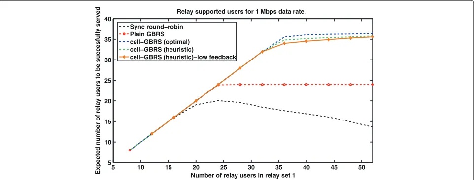
Figure 5Performance for increasing number of relay users.The figure compares the performance of the cell-GBRS scheme to baseline relaying scheme for increasing number of relay users. The number of users in relay set 1 are assumed to increase. Relay set 2 has 24 users and there are 24 macro-users in the cell.
relay users in relay set 1 (ref Figure 4) is increased from 2 to 13 per relay. They-axis shows the expected number of relay set 1 users who are successfully supported upon averaging over 1,000 realizations.
Thus, the total number of users in the cell (macro+2 relay sets) vary from 54 to 100. A 30% overhead would be incurred for downlink signaling. In addition, the frame durations are split evenly between the three user types: relay set 1, relay set 2, and macro. Taking the overhead and frame splits into account, we thus target a bit loading cor-responding to 2304 bits in a 0.5-ms time slot for providing 1 Mbps data rate.
We compare our proposed cell-GBRS scheme to base-line ‘Sync round-robin’ scheme. As can be observed in Figure 5, the performance of ‘Sync round-robin’ scheme drops down steadily as the number of users per relay increase beyond a certain limit of users, which is 24 requesting users in this case. The steady degradation can be understood by the shortcoming of admission control in baseline scheme. The main issue is that based on relay-level admissions,allusers in those relays are served with-out user level admission control. This effectively means that the round-robin access link from relays to some of those users quickly become a limiting factor. The peak
Table 2 Increasing relay user scenario parameters for the results
User type Number of users Data rate per user
Macro 24 500 kbps
Relay set 2 24 500 kbps
Relay set 1 8 to 52 1 Mbps
performance of baseline is 19 users when there are 24 requesting users.
In the ‘plain GBRS’ scheme, even though the access link is well optimized using the RRA subroutine, the lack of feeder link resources becomes a limiting factor. It can be noted that this limitation occurs rather quickly, for just around 24 users. However, the scheme is comparatively more robust (shows a performance saturation) as com-pared to the baseline because any additional user requests are simply dropped based on a hierarchical user-relay admission control.
Our proposed ‘cell-GBRS’ scheme overcomes the above-mentioned drawbacks by using optimized relay scheduling, hierarchical admissions, and inter-frame allocations for feeder link. RRA subroutine performs resource allocation for a much improved access link effi-ciency. Hierarchical admissions are done for user and relay selection. Free resources available after the ‘sort and greed’ macro-link scheduler are now allocated to the feeder link, which are called as inter-frame allocations. Thus, we observe a maximum of 36 users as compared to 24 users of the ‘plain GBRS’ scheme, which is a 50% performance improvement because of inter-frame alloca-tions. The improvement is 89.47% over the baseline ‘Sync round-robin’ scheduling scheme.
Importantly, we observe that this performance benefit is obtained even while avoiding interference in the inter-frame allocations. This interference avoidance is done via silencing the base station feeder link to relay set 1 when any relay in relay set 2 starts its transmission.
Table 3 Increasing macro user scenario parameters for the results
User type Number of users Data rate per user
Macro 8–24 500 kbps
Relay set 2 24 500 kbps
Relay set 1 52 1 Mbps
which is lower than the 1 Mbps requested by relay set 1 users.
Feedback rate
In this section, we discuss the issue of channel quality feedback overhead. Channel feedback conveys the follow-ing: 1 of 26 adaptive modulation and coding levels, the number of MIMO streams, and the best precoding matrix. Overall 12 feedback bits would be needed per resource block to convey the above information to the base station or relay transmitter. This corresponds to 576 bits to be sent by each user equipment within an arbitrary channel coherence interval. Even assuming a relaxed 10 ms chan-nel update interval and just ten users in the macro-cell, this would incur at least 576 kbps of uplink data rate per user (even without robust error protection coding). Thus, we see a situation of users in a cell requiring more than a 500-kbps uplink to enjoy a 500-kbps downlink.
We now consider an alternative reduced feedback scheme, similar to the extended feedback scheme which we presented in [5]. In this scheme, we now use only 4 MCS levels out of the 26 levels in [16]. The MCS lev-els indicate one of the following four options per spatial stream: 64QAM rate 2426, 16QAM rate 2430, QPSK rate 2430, and zero loading. No other coding options are considered, but three precoding options are still used. Furthermore,
only one MCS feedback is given for every six adjacent resource blocks (called a feedback block or a resource group block). The MCS of a feedback block is the min-imum of the MCS levels of the six constituent resource blocks. Thus, the number of feedback bits are now only 48 bits per channel coherence interval, which is a reduction of 91.7%.
Strikingly, our results in Figure 5 show that the perfor-mance sacrifice of cell-GBRS relaying is within 5% for this 91.7% reduction of feedback. This result can be under-stood from the signal measurement results in Figure 2, where a high SNR above 30 dB is observed in many indoor locations. It can thus be expected that high SNR users do not require a high level of uplink feedback to achieve high spectral efficiency. Importantly, this means they can also be served on any resource block with a high spec-tral efficiency. The net effect is a high scheduling degree of freedom that can be exploited for other medium to low SNR users based on frequency diversity (refer Step 3 in section RRA-suboptimal method). Thus, the resource blocks are more often well utilized for the few medium to low SNR indoor users.
Trade-off with macro users
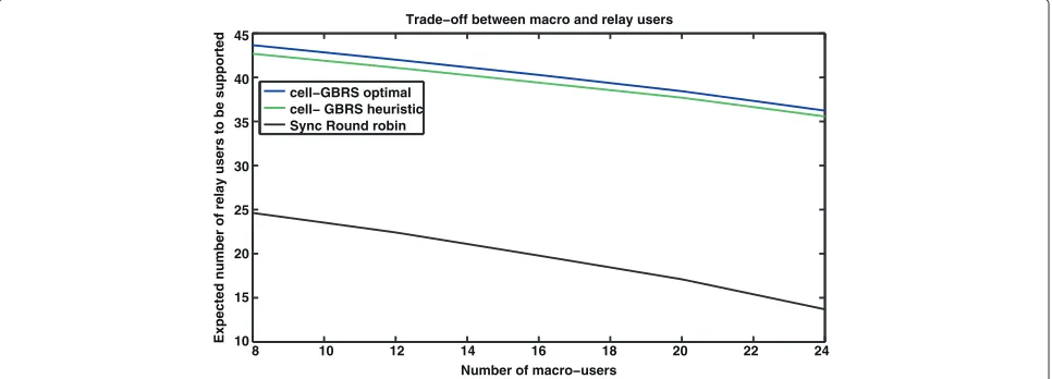
We now show results when the number of macro users increase as summarized in Table 3.
It can be deduced that as the number of macro-users increase the feeder bandwidth available for the relays would decrease. Thus, more efficient the macro-scheduler, better it is for the feeder link data rate. This effect can be observed in our results.
The results are shown in Figure 6, where we see the number of supported relay users of relay set 1 versus the number of macro users. For obtaining these results, relay set 2 users are fully served on their own frame and we
8 10 12 14 16 18 20 22 24
10 15 20 25 30 35 40 45
Trade−off between macro and relay users
Number of macro−users
Expected number of relay users to be supported
cell−GBRS optimal cell− GBRS heuristic Sync Round robin
500 550 600 650 700 750 800 850 900 950 1000 10−4
10−3 10−2
10−1
100
Data rate request of a particular user [Kbps]
User drop probability
Cell−GBRS (heuristic) Sync round−robin
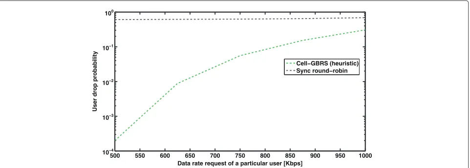
Figure 7User drop probability versus the data rate.The figure plots the chances of a user getting dropped against the requested data rate. There are 52 relay set 1 users, 24 relay set 2 users and 24 macro-users. Only one user in relay set 1 is assumed to vary the data rate request, whereas all the other user requests remain unchanged. The results are shown for the varying user.
also do not consider any free bandwidth available from relay set 2 frames. It is seen that both the cell-GBRS and the baseline schemes benefit from additional feeder band-width. When there are only 8 macro-users in the cell, 42 out of the 52 relay users in relay set 1 are supported suc-cessfully. In this scenario, we again see that cell-GBRS consistently outperforms the baseline scheme.
User drop versus the requested data rate
We now consider a different scenario as follows. Assume that relay set 2 has 24 users being served at 500 kbps. There are 24 indoor macro-users being served at the same data rate 500 kbps and relay set 1 has 52 users. We now generate results when only one user in relay set 1 low-ers the data rate request, while the other 51 uslow-ers request 1 Mbps as usual.
Figure 7 shows the results, where we show the user drop probability versus the data rate. Five thousand channel realizations were used to generate these results. A user is defined to be dropped in two cases: (a) when the admis-sion control does not admit the relay or user or (b) when the user is admitted but the requested data rate could not be served. Ideally, one would expect that a good schedul-ing scheme should support the user who lowers the data rate with higher probability. In Figure 7, we see that our scheduling scheme demonstrates this behavior quite well. In contrast, the round-robin scheme with relay admis-sions neglects the adaptiveness of the user. This is mainly because a relay is altogether rejected by the base sta-tion in relay-based admissions, if most other users of that relay request a higher data rate. This relay dropping would also happen when the users of another relay experience
3 4 5 6 7
0 10 20 30 40 50 60 70
Number of relay sets (4 relay cells per relay set)
Number of supported users
Number of supported users for a given number of relay sets. 1 Mbps bit rate
Cell GBRS : 4 users per relay cell
Cell GBRS : 4 users per relay cell. Reduced feedback. Sync Round robin Relay : 3 users per relay cell Sync Round robin Relay : 4 users per relay cell Direct Macro scheduling : 4 users per relay cell
Direct Macro scheduling. 4 users per relay cell. Reduced feedback.