R E S E A R C H
Open Access
Joint interference cancellation and relay
selection algorithms based on greedy
techniques for cooperative DS-CDMA systems
Jiaqi Gu
1*and Rodrigo C. de Lamare
1,2Abstract
In this work, we propose interference cancellation techniques and a multi-relay selection algorithm based on greedy methods for the uplink of cooperative direct-sequence code-division multiple access (DS-CDMA) systems. We first devise low-cost list-based successive interference cancellation (GL-SIC) and parallel interference cancellation (GL-PIC) algorithms with RAKE receivers as the front-end that can approach the maximum likelihood detector performance and be used at both the relays and the destination of cooperative systems. Unlike prior art, the proposed GL-SIC and GL-PIC algorithms exploit the Euclidean distance between users of interest and the potential nearest constellation point with a chosen threshold in order to build an effective list of detection candidates. A low complexity multi-relay selection algorithm based on greedy techniques that can approach the performance of an exhaustive search is also proposed. A cross-layer design strategy that brings together the proposed multi-user detection algorithms, and the greedy relay selection is then developed along with an analysis of the proposed techniques. Simulations show an excellent bit error rate performance of the proposed detection and relay selection algorithms as compared to existing techniques.
Keywords: DS-CDMA networks, Cooperative systems, Relay selection, Greedy algorithms, SIC detection, PIC detection
1 Introduction
Multi-path fading is a major constraint that seriously lim-its the performance of wireless communications. Indeed, severe fading has a detrimental effect on the received signals and can lead to a degradation of the transmis-sion of information and the reliability of the network. Cooperative diversity is a technique that has been widely considered in recent years [1] as an effective tool to deal with this problem. Several cooperative schemes have been proposed in the literature [2–4], and among the most effective ones are amplify-and-forward (AF) and decode-and-forward (DF) [4]. For an AF protocol, relays cooperate and amplify the received signals with a given transmit power amplifying their own noise. With the DF proto-col, relays decode the received signals and then forward the re-encoded message to the destination. Consequently, better performance and lower power consumption can be
*Correspondence: [email protected]
1Department of Electronics, University of York, YO10 5DD York, UK Full list of author information is available at the end of the article
obtained when appropriate decoding and relay selection strategies are applied.
1.1 Prior and related work
Direct-sequence code-division multiple access (DS-CDMA) systems are a multiple access technique that can be incorporated with cooperative systems in ad hoc and sensor networks [5–7]. Due to the multiple access interference (MAI) effect that arises from nonorthogonal received waveforms and narrowband interfering signals, the system performance may be adversely affected. To deal with this issue, multi-user detection (MUD) tech-niques have been developed [8] as an effective approach to suppress MAI. The optimal detector, known as max-imum likelihood (ML) detector, has been proposed in [9]. However, this method is infeasible for ad hoc and sensor networks considering its computational complex-ity. Motivated by this fact, several sub-optimal strategies have been developed: the linear detector [10], the suc-cessive interference cancellation (SIC) [11], the parallel
interference cancellation (PIC) [12], and the minimum mean-square error (MMSE) decision feedback detec-tor [13]. A key challenge is how to design interference cancellation techniques with low cost and near ML performance. Moreover, such interference cancellation algorithms should be suitable to cooperative relaying systems and feasible for deployment at the relays and small devices.
In cooperative relaying systems, different strategies that utilize multiple relays have been recently introduced in [14–18]. Among these approaches, a greedy algorithm is an effective way to approach the global optimal solu-tion. Greedy algorithms are important mathematical tech-niques that follow the approach of obtaining a locally optimal solution to complex problems with low cost in a step-by-step manner. Decisions at each step in the greedy process are made to provide the largest benefit based on improving the local state without consider-ing the global situation. Greedy algorithms may fail to achieve the globally optimal choice as they do not exe-cute all procedures exhaustively; however, they are still useful as they usually present a lower cost and can pro-vide acceptable approximations. Greedy algorithms have been widely applied in sparse approximation [19], internet routing [20], and arithmetic coding [21]. In [19], orthog-onal matching pursuit (OMP) and basis pursuit (BP) are two major greedy approaches that are used to approx-imate an arbitrary input signal with the near-optimal linear combination of various elements from a redundant dictionary. In [20], greedy routing is mentioned as a rout-ing strategy where messages are simply forwarded to the node that is closest to the destination. In order to reduce the computational complexity and improve the overall speed of arithmetic coding, a greedy re-normalization step that contains greedy thresholding and greedy out-putting is proposed and analyzed in [21]. In relay-assisted systems, greedy algorithms are used in [16, 17] to search for the best set of relays; however, with insufficient num-bers of combinations considered, a significant perfor-mance loss is experienced as compared to an exhaustive search.
1.2 Contributions
This work presents cost-effective interference cancella-tion algorithms and multi-relay seleccancella-tion algorithms for cooperative DS-CDMA systems. The proposed interfer-ence cancellation algorithms do not require matrix inver-sions and rely on the RAKE receiver as the front-end. A cross-layer optimization approach that jointly considers the proposed interference cancellation and relay selec-tion algorithms for ad hoc and sensor networks is also proposed. The proposed techniques are not limited to DS-CDMA systems and could also be applied to multi-antenna and multi-carrier systems. Cross-layer designs
that integrate different layers of the network have been employed in prior work [22, 23] to guarantee the quality of service and help increase the capacity, reliability, and coverage of systems. However, MUD techniques with relay selection in cooperative relaying systems have not been discussed widely in the literature. In [3, 24], an MMSE-MUD technique has been applied to cooperative systems, where the results indicate that the transmis-sions are more resistant to MAI and obtain a significant performance gain when compared with a single direct transmission. However, extra costs are introduced, as matrix inversions are required when an MMSE filter is deployed.
The contributions of this paper are summarized as fol-lows:
• We propose a low-cost greedy list-based successive interference cancellation (GL-SIC) multi-user detection method that can be applied at both the relays and the destination of wireless systems.
• We also develop a low-cost greedy list-based parallel interference cancellation (GL-PIC) strategy which employs RAKE receivers as the front-end and can approach the ML detector performance.
• We present a low-complexity multi-relay selection algorithm based on greedy techniques that can approach the performance of an exhaustive search.
• An analysis of the computational complexity, the greedy relay selection method, and the cross-layer design is presented.
• A cross-layer design that incorporates the
optimization of the proposed GL-SIC and GL-PIC techniques, and the improved greedy multi-relay selection algorithm for the uplink of a cooperative DS-CDMA system is developed and evaluated.
The rest of this paper is organized as follows. In Section 2, the system model is described. In Section 3, the GL-SIC multi-user detection method is presented. In Section 4, the GL-PIC multi-user detection method is then developed. In Section 5, the relay selec-tion strategy is proposed. In Secselec-tion 6, the computa-tional complexity and the greedy relay selection pro-cess are analyzed. In Section 7, the cross-layer design is explained. In Section 8, simulation results are pre-sented and discussed. Finally, conclusions are drawn in Section 9.
Notation: in this paper, we use boldface upper and bold-face lower fonts to denote matrices and vectors, respec-tively.(.)Tand(.)Hrepresent the transpose and Hermitian
2 Cooperative DS-CDMA system model
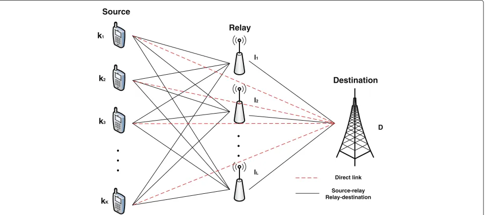
We consider the uplink of a synchronous DS-CDMA sys-tem withKusers(k1,k2,. . .kK),Lrelays(l1,l2,. . .lL),N
chips per symbol, and Lp (Lp < N) propagation paths
for each link. The system is equipped with a DF protocol at each relay, and we assume that the transmit data are organized in packets comprisingPsymbols. The received signals are filtered by a matched filter, sampled at chip rate to obtain sufficient statistics and organized intoM×1 vec-torsysd,ysr, andyrd, which represent the signals received from the sources (users) to the destination, the sources to the relays, and the relays to the destination, respectively. The proposed algorithms for interference mitigation and relay selection are employed at the relays and at the desti-nation. As shown in Fig. 1, the cooperation takes place in two phases. During the first phase, the received data at the destination and thel-th relay can be described by
ysd =
to the transmitted symbols,aksd andak
srl represent thek
-th user’s amplitude from -the source to -the destination and the source to relayl. The vectorshsd,k andhsrl,k are
the Lp× 1 channel vectors for user k from the source
to the destination and the source to relayl, respectively. TheM×1 noise vectorsnsd andnsrl contain samples of
zero mean complex Gaussian noise with varianceσ2. The
M×LpmatrixSkcontains the signature sequence of each
user shifted down by one position at each column that forms
sequence for userk. During the second phase of the trans-mission, each relay decodes and reconstructs the received signals using a DF protocol, then they forward the pro-cessed signals to the destination. It is assumed that each relay is perfectly synchronized and transmits at the same time; the signals received at the destination are then expressed by
whereakrld is the amplitude for source (user)kfrom the
l-th relay to the destination,hrld,k is theLp×1 channel
vector for userkfrom thel-th relay to the destination,nrd
is theM×1 zero mean complex Gaussian noise with vari-anceσ2, andbˆrld,kis the decoded symbol at the output of
relaylafter using the DF protocol.
The received signal at the destination comprises the data transmitted during two phases that are jointly pro-cessed at the destination. Therefore, the received signal is described by a 2M×1 vector formed by stacking the
.
received signals from the relays and the sources as given by
ysd yrd
= ⎡ ⎢ ⎢ ⎢ ⎣
K k=1
aksdSkhsd,kbk L
l=1
K k=1
akrldSkhrld,kbˆrld,k ⎤ ⎥ ⎥ ⎥ ⎦+
nsd nrd
. (5)
The received signal in (5) can then be described by
yd(i)=
K
k=1
CkHk(i)Ak(i)bk(i)+n(i), (6)
where i denotes the time instant corresponding to one symbol in the transmitted packet and its received and relayed copies.Ckis a 2M×(L+1)Lpmatrix comprising
shifted versions ofSkas given by
Ck= S0k 0S . . . 0 k . . . Sk
, (7)
Hk(i) represents a(L+1)Lp× (L+1) channel matrix
between the sources and the destination and the relays and the destination links as given by
Hk(i)= hsd,k0 h0 . . . 0 r1d,k . . . hrLd,k
. (8)
The matrixAk(i)is an(L+1)×(L+1)diagonal matrix of
amplitudes for userk,bk(i)=[bk,bˆr1d,k,bˆr2d,k,. . .bˆrLd,k]T is an(L+1)×1 vector for userkthat contains the trans-mitted symbol at the source and the detected symbols at the output of each relay, andn(i)is a 2M×1 noise vector. 3 Proposed GL-SIC multi-user detection
In this section, we detail the GL-SIC multi-user detector that can be applied in the uplink of a cooperative system. The GL-SIC detector uses the RAKE receiver as the front-end, so that the matrix inversion required by the MMSE filter can be avoided. The GL-SIC detector exploits the Euclidean distance between the users of interest and their nearest constellation points, with multiple ordering at each stage; all possible lists of tentative decisions for each
user are generated. When seeking appropriate candidates, a greedy-like technique is performed to build each list and all possible estimates within the list are examined when unreliable users are detected. Unlike prior work which employs the concept of Euclidean distance with multi-ple feedback SIC (MF-SIC) [25], GL-SIC does not require matrix inversions and jointly considers multiple numbers of users, constellation constraints, and re-ordering at each detection stage to obtain an improvement in detection performance.
3.1 Proposed GL-SIC design
In the following, we describe the process for initially detectingnusers described by the indicesk1,k2,. . .,knat
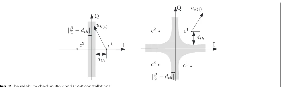
the first stage. Other users can be obtained accordingly. As shown by Fig. 2,βis the distance between two nearest constellation points,dthis the threshold. The soft output
of the RAKE receiver for userkis then obtained by
uk(i)=wHkysrl(i), (9)
where ysrl(i) represents the received signal from the source to the l-th relay,uk(i) stands for the soft output
of thei-th symbol for userk, andwk denotes the RAKE
receiver that corresponds to a filter matched to the effec-tive signature at the receiver. After that, we order all users according to a decreasing power level and organize them into a K × 1 vector ta. We choose the first n entries
[ta(1),ta(2),. . .,ta(n)] which denote users k1,k2,. . .,kn;
the reliability of each of thenusers is examined by the cor-responding Euclidean distance between the desired user and its nearest constellation pointcas explained next.
Decision reliable:
If allnusers are considered reliable
uta(t)(i) /∈Cgrey, fort∈[ 1, 2,. . .,n] , (10)
these soft estimates will then be applied to a slicerQ(·)as ˆ
bta(t)(i)=Q(uta(t)(i)), fort∈[ 1, 2,. . .,n] , (11)
10 15 20 25 30 30
35 40 45 50 55 60 65
M
computational complexity in flops (log−scale)
Matched filter Conventional SIC Conventional PIC Linear MMSE receiver GL−SIC
GL−PIC
Standard ML detector
Fig. 3Computational complexity in flops for various MUD detectors
wherebˆta(t)(i)denotes the detected symbol for theta(t)
-th user,Cgrey is the shadowed area in Fig. 2, it should be
noted that the shadowed region would spread along both the vertical and horizontal directions. The cancellation is then performed in the same way as a conventional SIC where we mitigate the impact of MAI brought by these users
ysrl,s+1(i)=ysrl,s(i)−
n
t=1
hsrl,ta(t)(i)bˆta(t)(i), (12)
where the italic fonthsrl,ta(t)(i) = asrlta(t)Sta(t)(i)hsrl,ta(t)(i)
stands for the desired user’s channel vector associated with the link between the source and thel-th relay and ysrl,s is the received signal from the source to the l-th relay at the s-th (s = 1, 2,. . .,K/n) cancellation stage. The process is then repeated with another set ofnusers being selected from the remaining users at the following stage, and this algorithm changes to the unreliable mode when unreliable users are detected. Additionally, since the interference created by the previous users with the
strongest power has been mitigated, improved estimates are obtained by reordering the remaining users.
Decision unreliable:
(a). If part of thenusers are determined as reliable, while others are considered as unreliable, we have
utp(t)(i) /∈Cgrey, fort∈[ 1, 2,. . .,np] , (13)
utq(t)(i)∈Cgrey, fort∈[ 1, 2,. . .,nq] , (14)
wheretpis a 1×npvector that containsnpreliable users
andtqis a 1×nqvector that includesnqunreliable users,
subject totp∩tq=∅andtp∪tq=[ 1, 2,. . .n] withnp+
nq = n. Consequently, the np reliable users are applied
to the slicerQ(·) directly and thenq unreliable ones are
examined in terms of all possible constellation pointscm
(m ∈[ 1, 2,. . .,Nc])from the 1×Ncconstellation points
setC ⊆ F, whereFis a subset of the complex field, Nc
is the number of constellation points, and the index ofm
Fig. 4GL-SIC comparison in non-cooperative system with 20 users over Rayleigh fading channel
the constellation points according to the modulation type. The detected symbols are given by
ˆ
btp(t)(i)=Q(utp(t)(i)), fort∈[ 1, 2,. . .,np] , (15) ˆ
btq(t)(i)=cm, fort∈[ 1, 2,. . .,nq] , (16)
At this point,Ncnqcombinations of candidates fornqusers
are generated. The detection tree is then split into Ncnq
branches. After this processing, (12) is applied with its corresponding combination to ensure that the interfer-ence caused by thendetected users is mitigated. Following that, Ncnq numbers of updated ysrl(i) are generated, we
reorder the remaining users at each cancellation stage and compute a conventional SIC with RAKE receivers for each branch.
The followingK×1 different ordered candidate detec-tion lists are then produced:
bj(i)=[spre(i), sp(i), sjq(i), sjnext(i)]T,j∈[ 1, 2,. . .,N nq c ] ,
(17)
where
spre(i)=[bˆta(1)(i),bˆta(2)(i),. . .]Tstands for the
previous stages detected reliable symbols,
sp(i)=[bˆtp(1)(i),bˆtp(2)(i),. . .,bˆtp(np)(i)]Tis anp×1
vector that denotes the current stage reliable symbols detected directly from slicerQ(·)when (13) occurs, sjq(i)=[cmtq(1),cmtq(2),. . .,cmtq(nq)]T,j∈[ 1, 2,. . .,N
nq c ]
is anq×1vector that contains the detected symbols
deemed unreliable at the current stage as in (14), each entry of this vector is allocated a value from the constellation point setC; therefore, since each entry goes through all possible constellation points, withnq
users contained insjq(i),N nq
c combinations need to
be considered and examined.j is the index number from allNcnq combinations ofsjq(i).
sjnext(i)=[. . .,bˆs
j q
t(1)(i),. . .,bˆ sjq
t(n)(i)]Tincludes the
corresponding detected symbols in the following stages after thej -th combination ofsq(i)is allocated
to the unreliable user vectortq,
Fig. 5GL-PIC comparison in non-cooperative system with 20 users over Rayleigh fading channel
(b). If allnusers are considered as unreliable, then we have
utb(t)(i)∈Cgrey, fort∈[ 1, 2,. . .,n] , (18)
where tb =[ 1, 2,. . .,n] and all n unreliable users can
assume the values inC. In this case, the detection tree will be split intoNcnbranches to produce
ˆ
btb(t)(i)=c
m, fort∈[ 1, 2,. . .,n] . (19)
Similarly, (12) is then applied and a conventional SIC with different orderings at each cancellation stage is performed via each branch.
Since all possible constellation values are tested for all unreliable users, we have the candidate lists
bj(i)=[spre(i), sjb(i), sjnext(i)]T, j∈[ 1, 2,. . .,Ncn] ,
(20)
where
spre(i)=[bˆta(1)(i),bˆta(2)(i),. . .]T are the reliable
symbols that are detected from previous stages,
sjb(i)=[cmt
b(1),c m
tb(2),. . .,c m tb(n)]
T,j∈[ 1, 2,. . .,Nn c]is a
n×1vector that represents the number of usersn which are regarded as unreliable at the current stage as shown by (18), each entry ofsjbis assigned a value from the constellation point setC.
The vectorsjnext(i)=[. . .,bˆs
j b
t(1)(i),. . .,bˆ sjb t(n)(i)]T
contains the corresponding detected symbols in the following stages after thej -th combination ofsb(i)is
allocated to all unreliable users.
After the candidates are generated, lists are built for each group of users, and the ML rule is used to choose the best candidate list as described by
bbest(i)=arg min
1≤j≤NcnqorNcn
ysrl(i)−Hsrl(i)bj(i)2,
(21)
whereHsrl(i) = hsrl,1 hsrl,2 . . . hsrl,Kis anM× K
Fig. 6BER versus SNR for uplink cooperative system
relay,hsrl,k =aksrlSk(i)hsrl,k(i)denotes aM×1 vector for
userkfrom the source to thel-th relay.
Clearly, GL-SIC is a SIC receiver that is split at stage
s into Ncnq parallel SIC receivers (branches) where s is
the first stage having unreliable users. The best branch is decided at the end using the ML criterion (minimum residual energy). The optimum performance occurs when we examine the reliability for all users. However, in this work, once unreliable users are detected at stage s, for the followings+1,s+2,. . . ,K/nstages, we process users directly through the conventional SIC detector to avoid further split of the detection tree as this would bring high complexity when large number of users are considered. Nevertheless, the performance gain can be compensated when increasing the number of usersnthat we considered per each stage.
The proposed GL-SIC algorithm is detailed in Algorithm 1.
3.2 GL-SIC with multi-branch processing
The multiple branch (MB) structure [13, 26] that employs multiple parallel processing branches can help to obtain extra detection diversity. Inspired by the MB approach
Fig. 7BER versus number of users for uplink cooperative system
[13, 26], we change the obtained best detection order for bbest with indices O =[ 1, 2,. . .,K] into a group of dif-ferent detection sequences to form a parallel structure with each branch sharing a different detection order. This approach generates lists with further candidates for detec-tion and can further improve the performance of GL-SIC. Since it is not practical to test allLb=K! possibilities due
to the high complexity, a reduced number of branches is employed. Note that a small number of branches capture most of the performance gains and allow the GL-SIC with the MB technique to approach the ML performance. With each index number inOlb being the corresponding index
number inOcyclically shifted to the right by one position as shown by
Ol1 =[K, 1, 2,. . .,K−2,K−1], Ol2 =[K−1,K, 1,. . .,K−3,K−2],
.. .
OlK−1 =[ 2, 3, 4,. . .,K, 1],
OlK =[K,K−1,K−2,. . ., 2, 1](reverse order).
Algorithm 1:The GL-SIC algorithm
uk(i)=wHkysrl(i)% soft outputs of all candidates
orderuk(i)according to a decreasing power level and
organize them intota
fors = 1toK/n
%Check whether unreliable users have already been detected from
previouss−1 stages or not
ifno unreliable users have been detected at previouss−1 stages
% Examine the reliability for each user for current stage s
fort=1: n
ifuta(t)(i) /∈Cgrey%reliable ˆ
bta(t)(i)=Q(uta(t)(i)) else %unreliable
ˆ
bta(t)(i)=cm end
end
Do conventional SIC via each branch
else% unreliable users have already been detected at previouss−1
stages
Re-order the n soft estimates for stage s and send them
to the slicerQ(·)
Perform conventional SIC in each branch end
end
% apply ML to choose the best candidates list bbest(i)=arg min1≤j≤Nnq
c orNcnysrl(i)−Hsrl(i)b j(i)2
obtainingK+1 different candidate lists according to each branch, a modified ML rule is applied with the following steps:
1. Obtain the best candidate branchbOlbase(i)among all
K+1(Oincluded) parallel branches according to the ML rule:
bOlbase(i)=arg min
0≤b≤Kysrl(i)−Hsrlb
Olb(i)2
(22)
2. Re-examine the detected symbol for userk
(k=1, 2,. . .,K)by fixing the detected results of all other unexamined users inbOlbase(i).
3. Replace thek -th user’s detection resultbˆkinbOlbase(i)
by its corresponding detected values from all otherK branchesbOlb(i),(lb =lbase,O=Ol0)with the same
index, the combination with the minimum Euclidean
distance is selected through the ML rule and the improved estimate of userk is saved and kept. 4. The same process is then repeated with the next user
inbOlbase(i)until all users inbOlbase(i)are examined.
The proposed modified ML selection technique is shown in Algorithm 2.
Algorithm 2:The modified ML selection process bopt=[ ] % define an empty vector initially fork = 1toK
forn = 1toK
bOln
temp=[bopt,bOln[k] ,b
Olbase[k+1] ,. . .,bOlbase[K] ] end
Apply ML rule to choose the best combination % save the corresponding estimate for user k from the selected
branchOlselectedthat provides the best combination bopt=[bopt,bOlselected[k] ]
end
4 Proposed GL-PIC multi-user detection
In this section, we present a GL-PIC detector that can be applied at both the relays and destination in the uplink of a cooperative system. The GL-PIC detector uses the RAKE receiver as the front-end, so that the matrix inversion brought by the MMSE filter can be avoided. Specifically, the proposed GL-PIC algorithm determines the reliability of the detected symbol by comparing the Euclidean dis-tance between the symbols of users of interest and the potential nearest constellation point with a chosen thresh-old. After checking the reliability of the symbol estimates by listing all possible combinations of tentative decisions, thenqmost unreliable users are re-examined via a number
of selected constellation points in a greedy-like approach, which saves computational complexity by avoiding redun-dant processing with reliable users. The soft estimates of the RAKE receiver for each user are obtained by
uk(i)=wHkysrl(i), (23)
As shown in Fig. 2, for thek-th user, the reliability of its soft estimates is determined by the Euclidean distance betweenuk(i)and its nearest constellation pointsc.
Decision reliable:
If the soft estimates of na users satisfy the following
condition
uta(t)(i) /∈Cgrey, fort∈[ 1, 2,. . .,na] , (24)
where ta is a 1 × na vector that contains na reliable
Fig. 8BER versus SNR for uplink cooperative system with different filters employed at the relays and the destination
area would extend along both the vertical and horizontal directions. These soft estimates are then applied to a slicer
Q(·)as described by ˆ
bta(t)(i)=Q(uta(t)(i)), fort∈[ 1, 2,. . .,na] , (25)
wherebˆta(t)(i)denotes the detected symbol for theta(t)
-th user.
Decision unreliable:
In case that nb users are determined as unreliable, a
1×nbvectortbwithnbunreliable estimates included is
produced, as given by
utb(t)(i)∈Cgrey, fort∈[ 1, 2,. . .,nb] , (26)
we then sort these unreliable estimates in terms of their Euclidean distance in a descending order. Consequently, the first nq users from the ordered set are deemed as
the most unreliable ones as they experience the farthest distance to their reference constellation points. Thesenq
estimates are then examined in terms of all possible con-stellation valuescm (m = 1, 2,. . .,N
c)from the 1×Nc
constellation points setC⊆ F, whereFis a subset of the complex field, and Nc is determined by the modulation
type. Meanwhile, the remainingnp = nb−nqunreliable
users are applied to the slicerQ(·)directly, as described by ˆ
btp(t)(i)=Q(utp(t)(i)), fort∈[ 1, 2,. . .,np] , (27)
ˆ
btq(t)(i)=cm, fort∈[ 1, 2,. . .,nq] , (28)
wheretp∩tq=∅andtp∪tq=tb.
Therefore, by listing all possible combinations of ele-ments across thenqmost unreliable users, the following
K×1 tentative candidate decision lists are generated bj=[sa, sp, sjq]T, j∈[ 1, 2,. . .,Ncnq] , (29)
where
sa =[bˆta(1),bˆta(2),. . .,bˆta(na)]Tis ana×1vector that
contains the detected values for thenareliable users, sp=[bˆtp(1),bˆtp(2),. . .,bˆtp(np)]Tis anp×1vector that
representsnpunreliable users that are detected by
the slicerQ(·)directly, sjq=[cmtq(1),c
m
tq(2),. . .,c m tq(nq)]
Tis an
q×1tentative
candidate combination vector. Each entry of the vector is allocated a value from the constellation point setC, and all possibleNcnq combinations need
The trade-off between performance and complexity is highly related to the modulation type and the number (nq)
of users we choose fromtb. Additionally, the threshold we
set at the initial stage is also a key factor that could affect the quality of detection.
After theNcnqcandidate lists are generated, the ML rule
is used subsequently to choose the best candidate list as described by
bopt=arg min
1≤j≤Ncnq
ysrl(i)−Hsrlbj(i)2. (30)
Following that, bopt is used as the input for a multi-iteration PIC process as described by
ˆ PIC iteration,bˆik denotes the detected value for userkat thei-th PIC iteration,Hsrl,jstands for the channel
matri-ces for the j-th user from the source to the l-th relay, wHsrl,k represents the RAKE receiver for userk from the source to the l-th relay, and bˆij−1 is the detected value for user j that comes from the (i − 1)-th PIC itera-tion. Normally, the conventional PIC is performed in a multi-iteration way, where for each iteration, PIC simul-taneously subtracts off the interference for each user produced by the remaining ones. The MAI generated by other users is reconstructed based on the tentative decisions from the previous iteration. Therefore, the accu-racy of the first iteration would highly affect the PIC performance as error propagation occurs when incorrect information imports. In this case, with the help of the GL-PIC algorithm, the detection performance is improved. The key novelty is that GL-PIC employs more reliable estimates by exploiting prior knowledge of the constella-tion points. The proposed GL-PIC algorithm is detailed in Algorithm 3.
5 Proposed greedy multi-relay selection method In this section, a greedy multi-relay selection method is introduced. For this problem, an exhaustive search of all possible subsets of relays is needed to attain the opti-mum relay combination. However, the major problem that prevents us from applying an exhaustive search in practical communications is its very high computational complexity. WithLrelays involved in the transmission, an exponential complexity of 2L−1 would be required. This fact motivates us to seek alternative methods. By elimi-nating the poorest relay-destination link stage by stage, the standard greedy algorithm can be used in the selec-tion process, yet only a local optimum can be achieved.
Algorithm 3:The GL-PIC algorithm
uk(i)=wHkysrl(i)% soft outputs of all candidates
Sort unreliable estimates tbin terms of the Euclidean distance
in a descending order
fort=1:nq% for the firstnqmost unreliable users ˆ
% Apply the ML rule to choose the best candidate list bopt=arg min1≤j≤Nnq
c ysrl(i)−Hsrlb j(i)2
% The three-iteration PIC process %boptis used as the input
Unlike existing greedy techniques, the proposed greedy multi-relay selection method can go through a sufficient number of relay combinations and approach the best one based on previous decisions. In the proposed relay selec-tion, the signal-to-interference-plus-noise ratio (SINR) is used as the criterion to determine the optimum relay set. The expression of the SINR for userqis given by
SINRq=
E[|wHqhq|2]
E[|η|2]+n, (32)
wherewqdenotes the RAKE receiver for userq,E[|η|2]
is the interference brought by all other users, andnis the noise. For the purpose of simplicity, the SINR for userq
after applying the RAKE receiver is given by
Fig. 9BER versus SNR for uplink cooperative system with different filters employed at the relays and the destination over a time-varying channel
where ρqq = hHqhq is the correlation coefficient of the
desired userq,ρkq=hHqhkis the cross-correlation
coeffi-cient between the signatures of userqand userk (interfer-ence component),hqis the channel vector for userqand
it should be mentioned that in various relay combinations, the channel vectorhqfor userq(q = 1, 2,. . .,K)is
dif-ferent as difdif-ferent relay-destination links are involved, and σ2
Nis the noise variance. This problem thus can be cast as
the following optimization:
SINRbest =max
r(q) {min(SINRr(q)),q=1,. . .,K},
(34)
whereqrepresents the index number for an arbitrary user, rdenotes a possible combination set(r ≤ L(L+1)/2)
of any number of selected relays, SINRr(q)represents the
SINR for userqin setr, and min(SINRr(q))= SINRr
means that the SINR for relay setris equal to the
min-imum SINR for a single user in setr.best is the best
relay set that provides the highest SINR.
Clearly, we can also consider the SINR for different relay combinations after applying convention SIC, conventional
PIC, linear MMSE, or even the proposed detectors. How-ever, RAKE receiver can bring the lowest complexity.
5.1 Standard greedy relay selection algorithm
The standard greedy relay selection method works in stages by removing the single relay according to the chan-nel path power, as given by
Phrld=hHrldhrld, (35)
wherehrldis the channel vector between thel-th relay and
the destination. At the first stage, the initial SINR is deter-mined when allLrelays are involved in the transmission. Consequently, we cancel the worst relay-destination link and calculate the current SINR for the remainingL−1 relays, as compared with the previous SINR, if
SINRcur >SINRpre, (36)
we update the previous SINR as
SINRpre =SINRcur, (37)
only one relay left. The selection is performed once at the beginning of each packet transmission.
5.2 Proposed greedy relay selection algorithm
In order to improve the performance of the standard algorithm, we propose a new greedy relay selection algo-rithm that is able to achieve a good balance between the performance and the complexity. The proposed method differs from the standard technique as we drop each of the relays in turns rather than drop them based on the channel condition at each stage. The algorithm can be summarized as:
1. Initially, a setAthat includes allL relays is
generated and its corresponding SINR is calculated, denoted bySINRpre.
2. For the second stage, we calculate the SINR forL combination sets with each dropping one of the relays fromA. After that, we choose the
combination set with the highest SINR for this stage, recorded asSINRcur.
3. CompareSINRcurwith the previous stageSINRpre, if
(36) is true, we save this corresponding relay combination ascurat this stage. Meanwhile, we update theSINRpreas in (37).
4. After moving to the third stage, we drop relays in turn again fromcurobtained in stage two.L−1 new combination sets are generated, we then select the set with the highest SINR and repeat the above process in the following stages until either
SINRcur<SINRpreor there is only one relay left.
This proposed greedy selection method considers the combination effect of the channel condition so that additional useful sets are examined. When compared with the standard greedy relay selection method, the previous stage decision is more accurate and the global optimum can be approached more closely. Furthermore, its com-plexity is less thanL(L+1)/2, which is much lower than the exhaustive search. Similarly, the whole process is per-formed only once before each packet and only needs to be repeated when the channels change. The proposed greedy multi-relay selection algorithm is depicted in Algorithm 4. Finally, it should also be noticed that relay selection can be also operated at the source-relay part as this is a two-phase process. However, in the current manuscript, we only consider the relay selection that occurs during the relay-destination links for the purpose of simplicity.
6 Analysis of the proposed algorithms
In this section, we analyze the computational complexity required by the proposed and existing interference cancel-lation algorithms and the proposed greedy relay selection method.
Algorithm 4:The proposed greedy multi-relay selec-tion algorithm
A=[ 1, 2, 3,. . .L]%Adenotes the set when all
relays are involved
SINRA =min(SINRA(q)),q=1, 2,. . .K SINRpre=SINRA
forstage =1toL−1 forr=1toL+1-stage
r=A−A(r)% drop each of the relays in turns
SINRr =min(SINRr(q)),q=1, 2,. . .,K
end for
SINRcur=max(SINRr) cur=SINRcur
ifSINRcur>SINRpreand|cur|>1 A=cur
SINRpre=SINRcur else
break end if end for
6.1 Computational complexity
We first compare the computational complexity of the proposed (GL-SIC and GL-PIC) and other existing inter-ference cancellation algorithms in terms of the required floating point operations (flops). The resulting complexity is calculated as a function of the following parameters:
• Total number of usersK.
• The number of multi-path channel componentsLp. • The number of constellation pointsNcthat
correspond to the modulation type.
• The parameterM which corresponds to the length of the receive filters, whereM=N+Lp−1andN is
the spreading gain.
Specifically, in the GL-SIC algorithm, n refers to the number of users we considered per each stage, and in the GL-PIC algorithm,nqrepresents the number of unreliable
users that need to be re-examined in the second process-ing stage. The required flops are considered both in the case of real and complex matrix operations. It is worth noting that, in real arithmetic, a multiplication followed by an addition requires two flops while for the complex num-bers, eight flops are required when an addition is executed after a multiplication. As a result, it can be approximated that the complexity of a complex matrix multiplication is four times of its real counterpart.
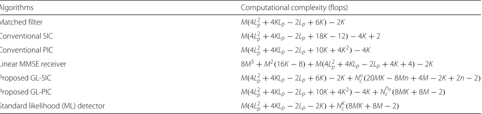
Table 1Computational complexity of existing and proposed MUD algorithms
Algorithms Computational complexity (flops)
Matched filter M(4L2
p+4KLp−2Lp+6K)−2K
Conventional SIC M(4L2
p+4KLp−2Lp+18K−12)−4K+2
Conventional PIC M(4L2
p+4KLp−2Lp+10K+4K2)−4K
Linear MMSE receiver 8M3+M2(16K−8)+M(4L2
p+4KLp−2Lp+4K+4)−2K
Proposed GL-SIC M(4L2
p+4KLp−2Lp+6K)−2K+Ncn(20MK−8Mn+4M−2K+2n−2)
Proposed GL-PIC M(4L2
p+4KLp−2Lp+10K+4K2)−4K+Nncq(8MK+8M−2)
Standard likelihood (ML) detector M(4L2
p+4KLp−2Lp−2K)+NKc(8MK+8M−2)
unreliable users may appear in any of the stages. As a result, the corresponding worst-case scenario is evaluated when all nusers are considered as unreliable at the first stage.
For each case shown in Table 1, the upper bound of the complexity is given by the standard ML detector, where it explores all possible combinations of the detected results and chooses the one with the minimum Euclidean dis-tance. However, when a large number of users need to be considered, an exponential complexity growth would limit its application in practical utilization. In contrast, with careful control of the number of unreliable usersn
andnq being re-examined in both proposed algorithms,
a substantial complexity saving is achieved. Additionally, our proposed greedy list-based algorithms offer a clear complexity advantage over the linear MMSE receiver as they adopt the RAKE receiver as the front-end, so that the cubic complexity can be avoided. Another feature to highlight is that although our proposed algorithms have a complexity slightly higher than the matched fil-ter, the conventional SIC, and the conventional PIC, they exhibit significant performance gains over existing techniques.
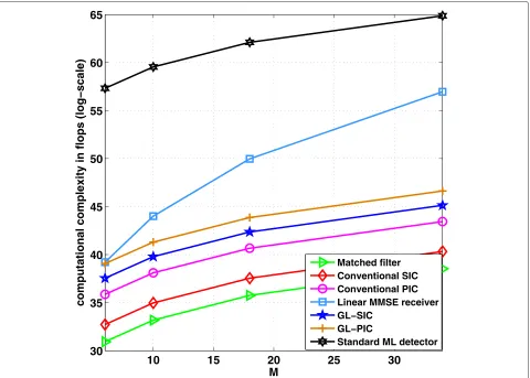
In order to further investigate the computational complexity for various MUD techniques, we fix the num-ber of usersK = 10, the number of multi-path channel
Lp=3, and assume that the BPSK modulation is adopted.
The required number of flops (log-scale) of the proposed and existing MUD algorithms are simulated in Fig. 3, where in the GL-SIC algorithm,n = 2 users are consid-ered jointly at each stage and in the GL-PIC algorithm,
nq = 3 unreliable users need to be re-examined in the
second processing stage. With the increase of the param-eter M, the standard ML detector climbs significantly faster than other MUD schemes, which, from another point of view, demonstrates that the improvement in its performance is achieved at the expense of a large increase in computational complexity. A similar com-plexity trend for the linear MMSE receiver illustrated in Fig. 3 shows a relatively lower complexity than the
standard ML detector; however, its complexity still sub-stantially exceeds that of the remaining strategies as a cubic cost is brought. Another important point observed in Fig. 3 is that our proposed algorithms offer a moder-ately higher cost than the matched filter, the conventional SIC, and the PIC, whereas they provide a considerable performance advantage over these schemes, result-ing in an attractive trade-off between complexity and performance.
6.2 Greedy relay selection analysis
The proposed greedy multi-relay selection method is a stepwise backward selection algorithm, where we optimize the selection based on the SINR criterion at each stage. We begin the process when all relays participate in the transmission and then subtract off the contributions brought by each of the relays from set of selected relays of the previous stage. The relay combinations generated at each stage are presented as follows:
Stage 1 : {11},
Stage 2 : {21,22,23,. . .,2L}, ..
.
Stage s : {s1,s2,3s,. . .,sL+2−s}, ..
.
Stage L−1 : {L1−1,2L−1,L3−1},
Stage L : {L1,L2},
where si denotes thei-th relay combination at thes-th stage. Clearly, the maximum number of relay combina-tions that we have to consider for allLstages is 1+2+3+ . . .+L=(1+L)L/2, since this algorithm stops either when SINRcur < SINRpre or when there is only one relay left,
Compared with the exhaustive search, which is consid-ered as the optimum relay selection method, the number of relay combinations examined at each stage is given by
Stage 1 : {11},
The total number of relay combinations can then be cal-culated asCLL+CLL−1+CLL−2+. . .+CL2+CL1=2L−1,
where each term Cmn = m(m−1)...(n!m−n+1) represents the number of combinations that we choose, i.e.,nelements frommelements(m≥n). The proposed greedy algorithm provides a much lower cost with a moderate to large num-ber of relays when compared with the exhaustive search as an exponential complexity is avoided.
In fact, the idea behind the proposed algorithm is to choose relay combinations in a greedy fashion. At each stage, we select the set of relays with the highest SINR and the previous stage result always affects the following stage set of relays candidates. Then, we subtract off the contri-bution brought by each of the remaining relays and iterate on the residual. After several stages, the algorithm is able to identify the optimum relay set. To this end, we propose the following proposition.
Proposition.The proposed greedy algorithm achieves an SINR that is bounded as follows:
SINRstandard≤SINRproposed≤SINRexhaustive
Proof.From the proposed greedy algorithm, the set containing the selected relay at thes-th stage is given by s sent the relaym, the relaynand the relayp, respectively.
We first prove the lower bound for an arbitrary stage
sby induction; other stages can be obtained accordingly. Assuming both algorithms achieve the same set at stages, we have
s
standard= {m,n,. . .,p}, s
proposed= {m,n,. . .,p},
which leads to the equality SINRs
standard =SINRsproposed, if we then proceed with the proposed greedy algorithm and choose a different set which provides a higher SINR, we have
standards = {m,n,. . .,p}, proposeds = {m,n,. . .,q},
with the only different relay being p = q, and assum-ing thatq provides a higher SINR than p, we prove the inequality that SINRsstandard≤SINRsproposed.
We then investigate the upper bound by comparing the proposed algorithm and the exhaustive search at an arbi-trary stages; other stages can be obtained accordingly. At an arbitrary stages, sinceproposeds is a candidate subset
of the exhaustive search, we have
exhaustives =max{exhautive(i)s,i∈[ 1,CLL+1−s]}, proposeds ∈ {exhautive(i)s,i∈[ 1,CL+1−s
L ]},
whereexhaustive(i)s represents thei-th relay combination
selected at the s-th stage of the exhaustive greedy relay selection method.
Assuming both strategies select the same relay combi-nation at stages, we have
proposeds = {m,n,. . .,p}, exhaustives = {m,n,. . .,p},
this situation again leads to the equality that SINRs
proposed = SINRsexhaustive. In contrast, if the exhaustive search picks another relay set belongs to {exhautive(i)s,i∈[ 1,CL+1−s
L ]}that provides a higher SINR,
clearly,proposeds = exhaustives, we can then obtain the
inequality that SINRproposeds ≤SINRexhaustives.
7 Proposed cross-layer design
In this section, we present and analyze a cross-layer design strategy that combines the proposed MUD tech-niques with the proposed greedy multi-relay selection algorithm for the uplink of the cooperative DS-CDMA networks. This approach jointly considers the perfor-mance optimization across different layers of the network, since inappropriate data detection and estimation that are executed at the lower physical layer can spread incor-rect information to the data and link layer where relay selection strategy performs, causing the loss of useful information and degradation of the overall system per-formance. In this case, when improved data detection is obtained at the physical layer, together with an effec-tive relay selection, a better system performance can be achieved.
the relays with a DF protocol; after the detection pro-cess, the proposed greedy multi-relay selection algorithm is then performed to seek the optimum relay combination. In the second phase, the chosen relays take part in the transmission in order to forward the information to the destination. After all the data are received at the destina-tion, the proposed MUD algorithms are applied to recover the transmitted data.
Given the received data ysd andysrl at the destination and each of the relays, we wish to optimize the over-all system performance in terms of the bit error rate (BER), through the selection of the received signals yrd at the destination from all relays, the accuracy of the detected symbols bˆrld,k at each of the relays, and the
detected resultsbˆkat the destination, subject to practical system constraints (K,L, Lp, Hsd,H(sr)l,Hrld). The
pro-posed cross-layer design can be cast into the following optimization problem
wherebjstands for thej-th candidate list generated after applying the GL-SIC/GL-PIC algorithms at the destina-tion,sdenotes stage index in the relay selection process, srepresents the selected relay combination at the stage
s, SINRs
i(k) is the SINR for thek-th user in thei-th relay
combination at stage s, and opt is the optimum relay combination obtained through the proposed greedy relay selection method. The cross-layer optimization in (38) is a non-convex optimization problem due to the discrete nature of the joint detection and relay selection problems. We propose to solve it in two stages using the proposed greedy detection and relay selection algorithms.
During the first phase, the received vector ysrl passes through the proposed GL-SIC/GL-PIC algorithms at the relay l, lists of candidate combinations bjrld are gener-ated in the lower physical layer, and the corresponding detected resultbˆrld,kis then obtained via the following ML
selection
ˆ
brld =arg min 1≤j≤NcnqorNcn
ysrl −Hsrlbjrld2. (39)
This interference cancellation operation affects the fol-lowing process in two different ways.
• The accuracy ofbˆrld,kdirectly controls the
re-generated signalsyrdreceived at the destination via the physical layer as can be verified from (4); hence, it further affects the decisionsbˆkmade at the
end as (5) computes.
• Improper detection ofbˆrld,kcan cause the error
propagation spreads in the second phase.
Consequently, in the second phase, the proposed greedy relay selection strategy is performed at the data and link layer; the selection takes into account the physi-cal layer characteristics as appropriate detection result coming from the lower physical layer can prevent error propagation spreading into the upper data and link layer. In contrast, it also considers the features of the channel combinations so that poor channels can be avoided.
In order to describe this process mathematically, we first define the SINR for thei-th relay combination at an arbitrary stagesas
SINRs
i =min {SINRsi(k)},k=1, 2,. . .,K. (40)
This algorithm operates in stages, and the SINR for the selected relay combination at each stage is given by
SINR1 =SINRA,1=A=[ 1, 2, 3,. . .,L] , and the optimum relay combination is then computed as opt = s. After that, the selected relays continue to
forward the re-generated signals to the destination in the second phase.
The proposed cross-layer design is detailed in Algorithm 5.
8 Simulations
In this section, a simulation study of the proposed multi-user detectors and the low-cost greedy multi-relay selec-tion method is carried out. The DS-CDMA network uses randomly generated spreading codes of lengthN =
32 and N = 16; it also employs Lp = 3
indepen-dent paths with the power profile [ 0,−3,−6 dB] for the transmission link. The corresponding channel coefficients are taken as complex Gaussian variables and normalized to ensure the average power is unity over the packet. Note that due to fading, there are variations over the transmission but we employ the total average power to set the signal-to-noise ratio (SNR). We assume perfectly known channels at the receiver. Equal power alloca-tion is employed during the transmission. The grey area in the GL-SIC and GL-PIC algorithm is determined by the threshold where dth = 0.25. We consider packets
with 1000 BPSK symbols and average the curves over 300 trials. For the purpose of simplicity, n = 2 users are considered in the GL-SIC scheme at each stage and for the GL-PIC strategy, a three-iteration PIC process
is adopted. The SNR is defined as SNR = σb2/σ2,
where σb2 corresponds to the signal power and σ2 is the noise power. The following simulations are compared and analyzed in both non-cooperative and cooperative scenarios.
The first example shown in Fig. 4 illustrates the per-formance comparison between the proposed GL-SIC interference suppression technique and other multi-user detection methods over the Rayleigh fading channel. The proposed GL-SIC algorithm uses the spreading codes with length N = 32, and the overall system is equipped with 20 users that only takes into account the source to the destination link. The conventional SIC detector is the standard SIC with RAKE receivers employed at each stage and the multi-branch multi-feedback SIC (MB MF-SIC) detection algorithm mentioned in [25] is pre-sented here for comparison purposes. We also produce the simulation results for the multi-branch SIC (MB-SIC) detector where four parallel branches with different detection orders are employed. Specifically, the detec-tion order for the first branch is obtained through a power decreasing level, while the detection orders for the remaining three are attained by cyclically shifting the order index from the previous branch to right by
Algorithm 5:The cross-layer desgin Phase I
%received signals from the source-destination link ysd=Hsdbk
%received signals from the source to thel-th relay ysrl =Hsrlbk
% Interference cancellation process at each of the relays
Apply the GL-SIC/GL-PIC algorithms at each of the relays to obtain bjrld
% Apply the ML rule to selectbˆrldfrombjrld ˆ
brld=arg min1≤j≤NcnqorNn
c ysrl −Hsrlb j rld2 Phase II
Apply the greedy multi-relay selection method SINRs
i =min {SINRsi(k)},k=1, 2,. . .,K
SINRs =max{SINRs i},
s
i =s−1\s−1(i),
i=1, 2,. . .,L+2−s
opt=swhen SINR
s <SINRs−1
%received signals from the selected relays to the destination yrd=
l∈opt
Hrldbˆrld
Apply the GL-SIC/GL-PIC algorithms at the destination to obtain bj % Apply the ML rule to selectbˆkfrombj
ˆ
b=arg min
1≤j≤NcnqorNcn
⎡ ⎣ ysd
l∈opt
Hrldbˆrld ⎤ ⎦−
Hsdbj l∈opt
Hrldbj 2
one position, similarly, RAKE receivers are adopted at each cancellation stage. Simulation results reveal that our proposed single branch GL-SIC significantly outper-forms the linear MMSE receiver and the conventional SIC and exceeds the performance of MB-SIC withLb =
4 and MB MF-SIC with Lb = 4 for the same BER
performance.
In the second example, the BER performance of the analyzed detection schemes is then examined for the proposed GL-PIC detector employed in the direct trans-mission over the Rayleigh fading channel,N = 32 and the user number is 20. As depicted in Fig. 5, the results compare the BER versus SNR performance between the conventional detectors and the GL-PIC techniques with different number of unreliable users being re-examined; the figure advises that the GL-PIC algorithm performs better than the conventional SIC detector and the conven-tional PIC detectors, both with RAKE receivers employed at each cancellation stage. Moreover, with the additional number of unreliable users being re-examined, extra performance gains can be obtained. However, in this non-cooperative Rayleigh fading system, the performance improvement is slight and the detection capability is not that good when compared with the GL-SIC scheme.
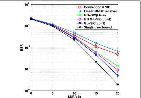
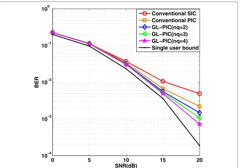
The next scenario illustrated in Fig. 6 shows the BER versus SNR plot for the cross-layer design using the pro-posed detectors and the greedy relay selection method, where we apply the GL-SIC/GL-PIC algorithms at both the relays and the destination in an uplink cooperative scenario with 10 users, 6 relays, and spreading gainN =
16. The performance bounds for an exhaustive search of different detectors are presented here for comparison purposes, where it examines all possible relay combina-tions and picks the best one with the highest SINR. From the results, it can be seen that with the relay selection, the GL-SIC(Lb = 1)detector performs better than the
GL-PIC detector in high SNR region. Furthermore, the BER performance curves of our proposed relay selection algo-rithm approach almost the same level of the exhaustive search, while keeping the complexity reasonably low for practical utilization.
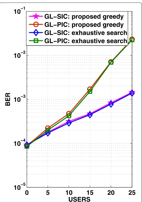
In contrast, when the algorithms are assessed in terms of BER versus number of users in Fig. 7 with a fixed SNR = 15 dB. Similarly, we apply both the GL-SIC and the GL-PIC detectors at both the relays and destination. The results indicate that the overall system performance degrades as the number of users increases. In particular, this figure also suggests that our proposed greedy relay selection method has a big advantage for situations with-out a high load and can approach the exhaustive search very closely with a relatively lower complexity. Addition-ally, the BER performance curves of GL-SIC detector is better than the GL-PIC detector especially for a large number of users.
In order to further verify the performance for the pro-posed cross-layer design, we compare the effect of differ-ent detectors with 10 users and 6 relays when this new greedy multi-relay selection algorithm is applied in the system. The results depicted in Fig. 8 with spreading gain
N = 16 indicate that the GL-SIC (Lb = 1) approach
allows a more effective reduction of BER and achieves the best performance that is quite close to the single user sce-nario, followed by the MB MF-SIC(Lb= 4)detector, the
MB-SIC(Lb = 4)detector, the GL-PIC detector, the
lin-ear MMSE receiver, the conventional SIC detector, and the conventional PIC detector. Additionally, it is worth noting that some extra performance gains are attained for the GL-PIC approach as morenqunreliable users are selected
and re-examined.
In order to see the capability of the proposed algorithms over time-varying channels, we then compare the perfor-mance of different detectors with 10 users and 6 relays over a time-varying channel. Specifically, the channels change over each transmitted block according to Clarke’s model with the symbol periodTs = 10−5 and the
max-imum Doppler shift fd = 20. Similarly, the proposed
greedy multi-relay selection method is adopted in the system and perfect channel state information (CSI) is assumed. The simulation results in Fig. 9 with spread-ing gain N = 16 suggest that the GL-SIC (Lb = 1)
achieves the best performance and can approach the single user bound very closely. This is then followed by the MB MF-SIC (Lb = 4) detector, the MB-SIC (Lb=4)detector, the GL-PIC detector, the linear MMSE receiver, the conventional SIC detector, and the conven-tional PIC detector. In addition, it is clear that when con-sidering the Doppler shift, the overall BER performance decreases.
In conclusion, in every scenario, the proposed SIC and PIC algorithms perform better than the standard SIC or PIC. In the literatures, a method of standard SIC receivers with forward error coding (FEC) has been introduced and can perform very well. However, it has also been showed that without FEC, standard SIC receivers can show per-formance degradation in certain situations (low SNR, highly loaded systems, etc.). As a result, the proposed SIC and PIC receivers have the advantage of consider-ing lists of potential candidates for detection, which can significantly improve the performance as compared to standard SIC/PIC receivers. We have limited our studies to uncoded scenarios but we acknowledge that the per-formance of GL-SIC and GL-PIC can be further improved with FEC.
9 Conclusions