Volume 2007, Article ID 56471,12pages doi:10.1155/2007/56471
Research Article
Capacity Performance of Adaptive Receive Antenna Subarray
Formation for MIMO Systems
Panagiotis Theofilakos and Athanasios G. Kanatas
Wireless Communications Laboratory, Department of Technology Education and Digital Systems, University of Piraeus, 80 Karaoli & Dimitriou Street, 18534 Piraeus, Greece
Received 15 November 2006; Accepted 1 August 2007
Recommended by R. W. Heath Jr.
Antenna subarray formation is a novel RF preprocessing technique that reduces the hardware complexity of MIMO systems while alleviating the performance degradations of conventional antenna selection schemes. With this method, each RF chain is not allo-cated to a single antenna element, but instead to the complex-weighted and combined response of a subarray of elements. In this paper, we derive tight upper bounds on the ergodic capacity of the proposed technique for Rayleigh i.i.d. channels. Furthermore, we study the capacity performance of an analytical algorithm based on a Frobenius norm criterion when applied to both Rayleigh i.i.d. and measured MIMO channels.
Copyright © 2007 P. Theofilakos and A. G. Kanatas. This is an open access article distributed under the Creative Commons Attribution License, which permits unrestricted use, distribution, and reproduction in any medium, provided the original work is properly cited.
1. INTRODUCTION
The interest in multiple-input multiple-output (MIMO) an-tenna systems has exploded over the last years because of their potential of achieving remarkably high spectral effi -ciency. However, their practical application has been limited by the increased manufacture cost and energy consumption of the RF chains (performing the frequency transition be-tween microwave and baseband) and analog-to-digital con-verters, the number of which is proportional to the number of antenna elements.
This high degree of hardware complexity has motivated the introduction of antenna selection schemes, which judi-ciously choose a subset from all the available antenna ele-ments for processing and thus decrease the number of nec-essary RF chains. Both analytical [1–11] and stochastic [12] algorithms for antenna selection have been proposed. How-ever, when a limited number of frequency converters are available, antenna selection schemes suffer from severe per-formance degradations in most fading channels.
In order to alleviate the performance degradations of conventional antenna selection, antenna subarray formation (ASF) has been recently introduced [13]. With this method, each RF chain is not allocated to a single antenna element, but instead to a combined and complex-weighted response of a subarray of antenna elements. Even though additional RF
switches (for selecting the antenna elements that participate in each subarray), variable RF phase shifters, or/and variable gain-linear amplifiers (performing the complex-weighting) are required with respect to antenna selection schemes, the proposed method achieves decreased receiver hard-ware complexity, since less frequency converters and analog-to-digital converters are required with respect to the full system.
at constructing subchannels (namely, subarrays) that are as mutually independent as possible and deliver the largest receive power gain, under the aforementioned constraints. Note that an RF preprocessing technique for reducing hard-ware costs has also been introduced in [20], but without grouping antenna elements into subarrays.
Initially, antenna subarray formation was introduced with the restriction that each antenna element participates in one subarray only. For this special case of ASF, the prob-lem of selecting the eprob-lements and the weights for the subar-ray formation has been addressed in [13], where an evolu-tionary optimization technique is used. In [21], we have in-troduced an analytical algorithm based on a Frobenius norm criterion. Recognizing that cost-effective analog amplifiers in RF with satisfactory noise figure are practically unavailable, we have also suggested a phase-shift-only design of the tech-nique [22]. Taking into consideration that the performance of ASF may be adversely affected by hardware nonidealities, such as insertion loss, calibration, and phase-shifting errors (which are not an issue in conventional precoder-decoder schemes), we have presented simulation results in [23] that indicate the robustness of ASF to such nonidealities.
In this paper, we elaborate on the capacity performance of ASF and the Frobenius-norm-based algorithm. In partic-ular, we derive a theoretical upper bound on the ergodic ca-pacity of the technique for Rayleigh i.i.d. channels. Moreover, we demonstrate the performance of the technique and the al-gorithm through extensive computer simulations and appli-cation to measured channels.
The rest of the paper is organized as follows:Section 2 ex-plains the proposed technique and its mathematical formu-lation in more detail, provides capacity calcuformu-lations for the resulted system and introduces some special ASF schemes. In
Section 3, tight theoretical upper bounds on the ergodic ca-pacity of the technique are derived.Section 4presents an an-alytical algorithm for ASF and its extensions for several ASF schemes. The capacity performance of the technique and the proposed algorithm is demonstrated inSection 5through ex-tensive computer simulations. Finally, the paper is concluded with a summary of results.
2. THE ANTENNA SUBARRAY FORMATION TECHNIQUE
In this section, we first present the antenna subarray for-mation technique and its mathematical formulation. After-wards, we provide capacity calculations for the resulted sys-tem. Finally, some special schemes of ASF are introduced, which are dependent on the number of phase shifters or/and variable gain-linear amplifiers available at the receiver.
2.1. MIMO system model
Consider a flat fading, spatial multiplexing MIMO system withMTelements at the transmitter andMR> MTelements
at the receiver. Unless otherwise stated, theMR×MTchannel
transfer matrixHis assumed to be perfectly known to the receiver, but unknown to the transmitter.
In spatial multiplexing systems, independent data streams are transmitted simultaneously by each antenna. The received vector forMRreceive elements is given by
y=Hs+n, (1)
where n is the zero-mean circularly symmetric complex Gaussian noise vector with covariance matrix Rn = N0IMR andsis the transmitted vector. Assuming that the total trans-mitter power isP, the covariance matrix for the transmitted vector is constrained as
trEssH=P, (2)
and the intended average signal-to-noise ratio per antenna at the receiver is
ρ= P
N0.
(3)
2.2. General mathematical formulation of antenna subarray formation
Antenna Subarray Formation can be applied with any num-ber of RF chains available at the receiver. However, without loss of generality, we assume that the receiver is equipped with exactly MT RF chains. This assumption is frequently
made in antenna selection literature and is justified by the well-known fact that, when the number of receiving RF chains becomes larger than the number of transmit anten-nas, the number of parallel spatial data pipes that can be opened is constrained by the number of transmit antennas. Thus, the receiver RF chains in excess cannot be exploited to increase the throughput, but can only offer increased diver-sity order [24]. This assumption is meaningful when the full system channel matrix is of full column rank.
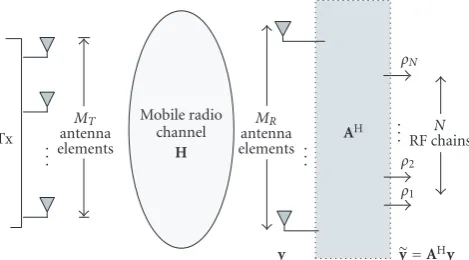
The process of subarray formation, complex weighting and combining at the receiver is linear and thus can be ade-quately described by the transformation matrixA. In partic-ular, the received vector after antenna subarray formationyis found by left multiplying the received vector forMRantenna
elements withAH, that is,
y=AHy. (4)
Thus, the response of the jth subarray yj (i.e., the jth
entry ofy) is
yj=αHjy=
MR
i=1
a∗i jyi, (5)
whereαjdenotes thejth column of A. Clearly, the response
of thejth subarrayyjis a linear combination of the responses
of theMRreceiving antenna elements and the conjugated
en-tries ofαjare the corresponding complex weights. Thus, (4)
is an adequate mathematical formulation of the subarray for-mation process, provided that we furthermore enforce the following restriction on the entries ofA:
Tx .
Figure1: System model of receive antenna subarray formation.
withSj denoting the set of receive antenna element indices that participate in the jth subarray.
Throughout this paper we assume that the transforma-tion matrixAis adapted to the instantaneous channel state. Thus, we should have written A(H), denoting the depen-dence on the full system channel matrixH. However, to fa-cilitate notation, we just writeAwhich henceforth implies
A(H).
By substituting (1) into (4), the received vector after sub-array formation becomes
y=AHHs+AHn. (7)
Apparently, the combined effect of the propagation chan-nel and the receive antenna subarrays on the transmitted sig-nal is described by the effective channel matrix
H=AHH. (8)
The effective noise component in (7) is
n=AHn, (9)
which is zero-mean circularly symmetric complex Gaussian vector (ZMCSCGV) [25] with covariance matrix:
Rnn=E
nnH=N
0AHA. (10)
The block model of the resulted system is displayed in
Figure 1.
2.3. Capacity of receive antenna subarray formation
Depending on the time-variation of the channel, there are different quantities that characterize the capacity of the resulted system. In this paragraph we apply well-known information-theoretic results for MIMO systems to RASF systems and elaborate the capacity of the proposed technique when different assumptions for channel-time variation are made.
2.3.1. Deterministic capacity
Deterministic capacity is a meaningful quantity when the static channel model is adopted, which implies that the chan-nel matrix, despite being random, once chosen it is held fixed
for the whole transmission. In this case, the Shannon capac-ity of RASF is given in terms of mutual information between the transmitter vectorsand the received vector after subarray formationyas
CRASF= max ter. Recognizing that the transmitted symbols are indepen-dent from noise, assuming thatsis ZMCSCGV [25,26] and taking into account thatn∼NC(0,N0AHA), we find that
ance matrix ofy. After some mathematical manipulations, (12) becomes
Since the transmitter does not know the channel and tak-ing into account the power constraint, it is reasonable to as-sume that
Rs= P
MT
IMT. (14)
Thus, the Shannon capacity of receive antenna subarray formation with equal power allocation at the transmitter is
CRASF=log2det
The capacity of the resulted system is upper bounded by the capacity of the full system, that is
CRASF≤CFS=log2det
Proof of this result is given inAppendix A.
2.3.2. Ergodic capacity
ρ and phase shifters
ρN
Figure2: Receiver structures for several receive antenna subarray formation (ASF) schemes: (a) strictly-structured ASF (SS-ASF), (b)
relaxed-structured ASF (RS-ASF) and (c) reduced hardware complexity ASF (RHC-ASF).
2.3.3. Outage capacity
Outage capacity is a meaningful quantity in slowly varying channels. Assuming a fixed transmission rateR, there is an associated probabilityPout (bounded away from zero) that
the received data will not be received correctly, or equiva-lently that mutual information will be less than transmission rateR. Outage capacity for RASF is therefore defined as
CRASF=R: Pr
2.4. Receive antenna subarray formation schemes
In general, no more constraints on the transformation ma-trixAare required. However, depending on the number of available phase shifters or/and variable gain-linear amplifiers (which determine the number of its nonzero entries), fur-ther restrictions on matrixAmay be necessary. Motivated by these practical considerations, we have introduced several variations of antenna subarray formation [22], namely, the following.
(1) Strictly-Structured ASF (SS-ASF), in which each
an-tenna element is allowed to participate in one subar-ray only. Thus, each row of the transformation matrix
Amay contain only one nonzero element, whereas no restriction is enforced on the columns of A. With this scheme, exactly MR phase shifters and variable
gain-linear amplifiers are required at the receiver.
(2) Relaxed-Structured ASF (RS-ASF), where no
restric-tions on matrixAare imposed, except for the num-ber of its nonzero entries, which is a fixed system de-sign parameter that determines the number of phase shifters and variable gain-linear amplifiers available to the receiver.
(3) Reduced Hardware ComplexityASF (RHC-ASF), which
is a phase-shift-only design of the technique. While cost-effective variable gain-linear amplifiers with sat-isfactory noise figure are not practically available, the economic design and manufacture of variable phase-shifters for the microwave frequency is feasible due to the rapid advances in MMIC technology. Therefore, this scheme reduces even further the hardware com-plexity of the receiver with negligible capacity loss, as it will be demonstrated inSection 5.
An efficient algorithm for determining the transforma-tion matrixAfor all the aforementioned schemes will be pre-sented in detail inSection 4.Figure 2presents the receiver ar-chitecture for each of the ASF schemes.
3. AN UPPER BOUND ON THE ERGODIC
CAPACITY OF ANTENNA SUBARRAY FORMATION FOR I.I.D. RAYLEIGH CHANNELS
A well-known upper bound on the (deterministic) capac-ity of the full system is given by
CFS≤
whereγiare independent chi-squared variates with2MR
de-grees of freedom. The equality holds in the “very artificial case” when the transmitted signal vector components “are conveyed overMT “channels” that are uncoupled and each
channel has a separate set of MR receive antennas” [27].
In other words, when the full MIMO system is consisted of MT separable and independent parallel SIMO systems,
each performing maximum ratio combining (MRC) at the receiver.
In our case, we consider as well that the resulted system is consisted ofMT separable and independent parallel SIMO
systems. We suppose that the jth SIMO system is formed by the jth transmit antenna element and thejth receive subar-ray; thus, for each subarray, only one signal component is re-ceived and processed without any interference from the oth-ers. Of course, this scheme is practically infeasible; however, it must lead to an upper bound of the resulted system capac-ity.
A subarray corresponds to an independent SIMO system and is actually formed by choosing a subset of antenna el-ements, the responses of which are linearly combined and fed to an RF chain. Thus, generalized selection combining (i.e., combining the responses of a subset of antenna ele-ments) is performed in each SIMO system. The maximum SNR (which also achieves maximum capacity) in this case is obtained with the hybrid selection maximum ratio com-bining scheme (HS/MRC). Furthermore, in this section, we assume that each subarray is formed using a predefined and fixed number of antenna elements (let it bekj antenna
ele-ments for the jth subarray). Therefore, a capacity bound for antenna subarray formation can be obtained by
Cbound=
Assuming that there are no delay constraints, the channel
isergodicand therefore it is meaningful to derive an upper
bound onergodic capacityas
Cbound=
Sinceξj is actually the postprocessing SNR of HS/MRC
whenkjout ofMRelements are chosen, its probability
den-sity function is [29]
Substituting (23) into (22) and defining the integral
In(x)=∧
which, in fact, is the average channel capacity achieved when employing HS/MRC in a SIMO system withMRreceiving
an-tenna elements andkjbranches.
The integralIn(x) can be evaluated by [30]
Note thatE1(x)is the exponential integral of first-order
function defined by
E1(x)=
∞
x
e−t
t dt (28)
andΓ(α,x) is the complementary incomplete gamma func-tion (or Prym’s funcfunc-tion) defined as
Γ(α,x)=
∞
xt
Forqpositive integer,Γ(−q,x) can be calculated by
Thus, the ergodic capacity bound for receive antenna subarray formation can be analytically obtained by
Cbound=
A simpler expression than (25) can be derived by rec-ognizing that log2(·) is a concave function and applying
Jensen’s inequality to (21),
cj=E
which has a much simpler form than (31) while being almost as tight as computer simulations have demonstrated.
Before concluding this section, we note that analyzing the resulted system into parallel SIMO systems each perform-ing HS/MRC results into capacity bounds of RS-ASF, since HS/MRC requires both phase shifters and variable gain am-plifiers. Capacity bounds for RHC-ASF could be derived in a similar manner by consideringMT parallel SIMO systems
each performing HS/EGC. Since HS/MRC delivers the best performance amongst all hybrid selection schemes, the up-per bound on the ergodic capacity of RS-ASF is also an upup-per bound on the ergodic capacity of any ASF scheme, including RHC-ASF.
4. ALGORITHM FOR ANTENNA SUBARRAY FORMATION
In this section, we present a novel, analytical algorithm for receive antenna subarray formation, based on a Frobenius
norm criterion. We first develop the algorithm for SS-ASF and then provide extensions for RS-ASF and RHC-ASF. The capacity performance of the algorithms will be demonstrated inSection 5.
4.1. Starting point for the algorithm
The starting point for determining the transformation ma-trixAwill be an optimal solution to theunconstrained prob-lem of maximizing the deterministic capacity in (15). As shown inAppendix A, (15) can be maximized whenAo=U,
where the columns of Uare theMT dominant left singular
vectors of the full channel matrixH. Therefore, the entries of the transformation matrixAwill be
ai j=
ui j ifi∈Sj
0 otherwise, (35)
withui jbeing the (i,j) entry of matrixU. Alternatively,
A=S U, (36)
where denotes the Hadamard (elementwise) matrix prod-uct and the entries ofSare
si j=
1 i∈Sj
0 otherwise. (37)
4.2. Frobenius norm based algorithm for SS-ASF
We first develop an algorithm for SS-ASF and afterwards ex-tend it for other receive ASF schemes. Due to the additional constraints of SS-ASF, the capacity of the resulted system is given by
In order to retain the capacity calculations to the in-tended system SNR measured at the output of every receiver antenna element,Ais now subject to the following normal-ization:
AHA=I
MT. (39)
Intuitively, the desired transformation matrixAshould be such that the distance between the two subspaces defined byHopt = UHH(i.e., the effective channel matrix obtained
from the optimal solution to the unconstrained problem) andH =AHHis minimized. As a result, we employ the
fol-lowing minimum distance distortion metric:
Table1: Frobenius-norm-based algorithm for RASF.
Compute the decision metricsgi jthat will
determine if theith antenna element will participate in thejth subarray.
Fori:=1 toMR
Sj: set of indices of antenna elements that
partic-ipate in thejth subarray. A:=0MR×MT;n:=0
Repeat the following until matrixAis filled with
Knonzero elements:
Whilen<K
element participates in thej0th subarray;
n:=n+ 1 end
for SS-ASF only, normalizeAso that For SS-ASF only:
AHA=I
Recognizing that theith row of matrixFcan be written as a linear combination of the rowshiof the full system channel
matrixHand taking into account that
ei j=∧ ui j−ai j=
ui j i∈Sj
0 i∈Sj, (42)
the distortion metric becomes
ε(A)=
where the upper bound on the right-hand side follows from the triangular inequality. As a result, the objective is to mini-mize the upper bound on the distortion metric in (43).
Since the selection of the elements of the transformation matrixAis based on matrixU, it is trivial to conclude that minimizing the upper bound in (43) is equivalent to maxi-mizing
which upper-bounds the power of the effective channel ma-trixH 2F. Indeed, after mathematical manipulations similar
to those in (41)–(43), it follows that
matrixA. Consequently, minimizing an upper bound on the minimum distance distortion metric is equivalent to maxi-mizing an upper bound on the power of the effective channel matrix. The latter may not be the optimal way to maximize capacity in spatial multiplexing systems, but it should result into an increased capacity performance, since it is known that [24]
The proposed algorithm appoints the receiver antenna el-ements to the appropriate subarray, so that the metric (44) is maximized. Finally, A is normalized as in (39). Table 1
4.3. Extension of the algorithm for RS-ASF
The capacity of RS-ASF given by (15) is lower bounded by the capacity formula (38) for SS-ASF, that is,
CRS-ASF≥log2det
IMT+ ρ
MT
HHAAHH
. (47)
Proof of this result and indications for the tightness of the bound are provided inAppendix B.
Thus, in the case of RS-ASF we also use the Frobenius norm based algorithm initially developed for SS-ASF. The al-gorithm terminates when the transformation matrixA con-tains exactlyKnonzero elements, whereK < MRMTis a
sys-tem design parameter that determines the number of vari-able gain-linear amplifiers and phase shifters availvari-able to the receiver.
The computational complexity of the proposed algo-rithm (seeTable 1) is dominated by the initial cost of the sin-gular value decomposition, that is,O(M3
R) whenMR MT,
whereas the complexity of Gorokhov et al. algorithm [4] and of the alternative implementation proposed in [5] for an-tenna selection isO(M2
TMR2) andO(MT2MR), respectively. 4.4. Extention of the algorithm for RHC-ASF
The transformation matrixAfor RHC-ASF (a phase-shift-only design of antenna subarray formation) can be obtained from the transformation matrixAfor RS-ASF by applying the following formula to its entries:
ai j=
⎧ ⎨ ⎩
exp−j|ai j ifi∈Sj
0 otherwise. (48)
Intuitively, RHC-ASF follows the notion of equal gain combining. A similar procedure for obtaining a phase-shift-only RF preprocessing technique has been followed in [20].
5. SIMULATION RESULTS
In this section, we present extensive computer simulation re-sults that demonstrate the capacity performance of receive ASF technique, the tightness of the ergodic capacity bounds derived in Section 3, and the performance of the proposed algorithm.
5.1. Upper bound on ergodic capacity for ASF
We first deal with the ergodic capacity bounds of ASF for Rayleigh i.i.d. channels derived in Section 3, namely, (31) and (34). Henceforth, we refer to (34) as “simpler theoretical capacity bound,” in order to distinguish it from (31). We con-sider a flat-fading Rayleigh i.i.d. MIMO channel withMR=8
receiving andMT=2 transmitting antenna elements and
as-sume that the receiver is equipped withN = MT = 2 RF
chains.
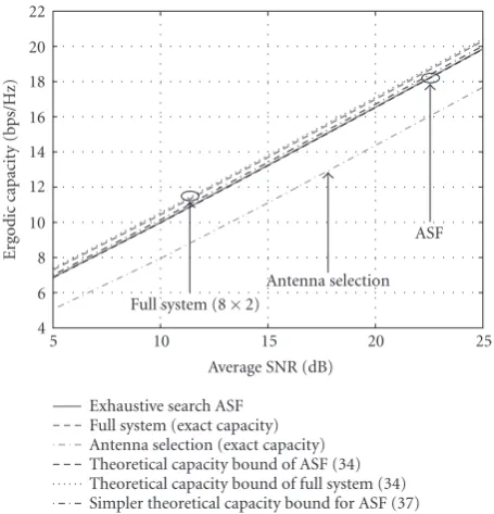
Figure 3presents the ergodic capacity bounds of RS-ASF over a wide range of SNRs whenK =8 variable gain-linear amplifiers and phase shifters are available at the receiver and
4 6 8 10 12 14 16 18 20 22
Ergodic
capacit
y
(bps/Hz)
5 10 15 20 25
Average SNR (dB) Exhaustive search ASF
Full system (exact capacity) Antenna selection (exact capacity) Theoretical capacity bound of ASF (34) Theoretical capacity bound of full system (34) Simpler theoretical capacity bound for ASF (37)
Full system (8×2)
Antenna selection ASF
Figure3: Ergodic capacity bounds for ASF and capacity of
exhaus-tive search ASF whenMR =8,MT =2, andK =8 variable
gain-linear amplifiers and phase shifters are available at the receiver (4 antenna elements in each subarray). Results are compared to an er-godic capacity bound and exact erer-godic capacity of the full system.
exactly k =∧ K/N = 4 receiving antenna elements partici-pate in each subarray. For purposes of reference, the ergodic capacity of the exhaustive search solution of RS-ASF is also shown. The exhaustive search solution is obtained by consid-ering all theMR
k N
possible combinations of subarray for-mation, that is, all possible combinations for the structure of matrixSas defined in (37), assuming thatAis obtained as in (36). Apparently, both capacity bounds are very tight to the exhaustive search solution.
When each subarray containsMRantenna elements, the
capacity bound of the MIMO system is found by analyzing it intoMTparallel SIMO systems. Each of these parallel systems
reduces to a MRC diversity system and therefore the ergodic capacity bound of the full system will be obtained by (31). This observation is verified inFigure 3.
5.2. Frobenius-norm-based algorithm
In this paragraph we demonstrate the capacity performance of the Frobenius-norm-based algorithm for various schemes of receive ASF in terms of outage capacity (when the slowly-varying block fading channel model is adopted) and ergodic capacity (when the channel is assumed ergodic). The pro-posed algorithm is applied to both Rayleigh i.i.d. and mea-sured MIMO channels.
5.2.1. Rayleigh i.i.d. channels
We consider Rayleigh i.i.d. MIMO channels withMT = 2
0 0.1 0.2 0.3 0.4 0.5 0.6 0.7 0.8 0.9 1
P
rob
.(capacit
y
>
abscissa)
9 10 11 12 13 14 15
Capacity (bps/Hz) Antenna selection
Frobenius norm based algorithm for RASF (K=8) Exhaustive search RASF (K=8)
Full system (8×2)
Figure 4: Empirical complementary cdf of the capacity of the
resulted system when the Frobenius-norm-based algorithm for strictly structured receive antenna subarray formation (SS-ASF) is applied to a 8×2 Rayleigh i.i.d. channel with SNR=15 dB. The per-formance of the algorithm is compared with the exhaustive search solution for SS-ASF, the full system (8×2), and Gorokhov et al. decremental algorithm for antenna selection.
equipped withMT =8 elements,N =MT =2 RF chains,
andK =8 phase shifters or/and variable gain-linear ampli-fiers.
Figure 4presents the complementary cdf of the capacity of the resulted system for SS-ASF when the SNR is at 15 dB. Clearly, SS-ASF outperforms Gorokhov et al. algorithm for antenna selection [4], which is quasi optimal in terms of ca-pacity performance. Moreover, the performance of the pro-posed algorithm is very close to the exhaustive search solu-tion. Thus, the SS-ASF technique delivers a significant capac-ity increase with respect to conventional antenna selection schemes. The same results are verified inFigure 5, where the ergodic capacity of the resulted system over a wide range of SNRs is plotted.
5.2.2. Measured channel
In order to examine the performance in realistic conditions, we have applied the proposed algorithm to measured MIMO channel transfer matrices. Measurements were conducted us-ing a vector channel sounder operatus-ing at the center fre-quency of 5.2 GHz with 120 MHz measurement bandwidth in short-range outdoor environments with LOS propagation conditions. A more detailed description of the measurement setup can be found in [31]. The transmitter hasMT = 4
equally spaced antenna elements and the receiver is equipped with MR = 16 receiving elements andN = MT = 4 RF
chains. The interelement distance for both the transmitting and receiving antenna arrays isd=0, 4λ.
4 6 8 10 12 14 16 18 20 22
Ergodic
capacit
y
(bps/Hz)
5 10 15 20 25
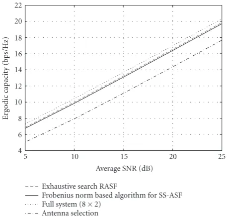
Average SNR (dB) Exhaustive search RASF
Frobenius norm based algorithm for SS-ASF Full system (8×2)
Antenna selection
Figure5: Performance evaluation of strictly structured ASF
(SS-ASF) applied to an 8×2 MIMO Rayleigh i.i.d. channel, in terms of ergodic capacity. The performance of the algorithm is compared to the exhaustive search solution for receive ASF, the full system (8×2), and Gorokhov et al. decremental algorithm for antenna selection.
Figure 6displays the complementary cdf of the capacity of the resulted system when the Frobenius-norm-based al-gorithm is applied to several schemes of receive ASF and for various values ofK(i.e., the number of phase shifters or/and variable gain-linear amplifiers). Clearly, all ASF schemes out-perform conventional antenna selection.
Solid black lines correspond to RS-ASF (or SS-ASF for K=MR=16) and dashed black lines to RHC-ASF.
Compar-ing the solid with the dashed lines for the same value ofK, it is evident that RHC-ASF delivers capacity performance very close to RS-ASF. Therefore, the expensive variable gain-linear amplifiers can be abolished from the design of ASF with neg-ligible capacity loss.
ForK = 48, the capacity performance of RS-ASF and RHC-ASF is very close to the full system, despite the fact that in ASF the receiver is equipped with onlyN =MT =4 RF
chains (whereas the full system hasMR=16 RF chains). Even
whenK =32, the capacity loss with respect to the full sys-tem is still quite low (10% outage capacity loss of RHC-ASF is less than 1.5 bps/Hz at 15 dB). Similar results are observed for a wide range of signal-to-noise ratios (Figure 7). Conse-quently, the proposed algorithm can deliver near-optimal ca-pacity performance with respect to the full system while re-ducing drastically the number of necessary RF chains.
6. CONCLUSIONS
0
Figure6: Empirical complementary cdf of the capacity of the
re-sulted system when the Frobenius-norm-based algorithm for sev-eral schemes of receive antenna subarray formation (ASF) is ap-plied to a 16×4 measured channel with SNR=15 dB. In particu-lar, the RASF schemes studied are strictly structured ASF (SS-ASF), relaxed-structured ASF (RS-ASF), and reduced hardware complex-ity ASF (RHC-ASF).Kdenotes the number of phase shifters or/and variable gain-linear amplifiers available to the receiver. The perfor-mance of the algorithm is compared to the full system (16×4) and Gorokhov et al. decremental algorithm for antenna selection.
5
Average SNR (dB) Antenna selection
ASF (K=16) ASF (K=32)
Full system (16×4)
Figure7: Performance evaluation of Frobenius-norm-based
algo-rithm for several schemes of receive antenna subarray formation (RASF) applied to a 16×4 MIMO measured channel, in terms of er-godic capacity. In particular, the RASF schemes studied are strictly structured ASF (SS-ASF), relaxed-structured ASF (RS-ASF) (solid lines), and reduced hardware complexity ASF (RHC-ASF) (dotted lines).Kdenotes the number of phase shifters or/and variable gain-linear amplifiers available to the receiver. The performance of the algorithm is compared to the full system (16×4) and Gorokhov et al. decremental algorithm for antenna selection.
adaptively grouping receive array elements to subarrays. Ap-plication in Rayleigh i.i.d. and measured channels demon-strates significant capacity performance, which can become near optimal with respect to the full system, depending on
the number of available phase shifters or/and variable gain-linear amplifiers. Furthermore, it has been shown that a phase-shift-only design of the technique is feasible with neg-ligible performance penalty. Thus, it has been established that antenna subarray formation is a promising RF prepro-cessing technique that reduces hardware costs while achiev-ing incredible performance enhancement with respect to conventional antenna selection schemes.
APPENDICES
Thus, the capacity formula in (15) becomes
CRASF=log2det
Applying the known formula for determinants [32]
det (I+AB)=det (I+BA) (A.3)
which can be written as
CRASF=
whereλm(X) denotes themth eigenvalue of square matrixX
in descending order. Poincare separation theorem [32] states that
with equality occurring when the columns ofUAare theMT
dominant left singular vectors ofH. Thus,
where equality occurs when
UA=
u1 u2 · · · uMT
(A.8)
andukis thekth dominant singular vector ofH. Therefore,
anoptimal solution to the unconstrained (i.e., without the
subarray formation constraints in (6) capacity maximization problem is
Ao=
u1 u2 · · · uMT
Q, (A.9)
where Q = ΣAVHA is a matrix with orthogonal rows and
columns.
B.
LetA =UAΣAVHA be a singular value decomposition of the
transformation matrix A. Exploiting Hadarmard’s inequal-ity for determinants [32] and after some trivial mathematical manipulations, it follows that
detΣ2A =det
VAΣ2AVHA =det
AHA ≤ MT
k=1
AHAkk
= MT
k=1
aHkak= MT
k=1
ak2
≤1,
(B.1)
where ak denotes the kth column of the
transforma-tion matrix A. The last inequality in (B.1) follows from
ak ≤ uk =1, withuk being thekth left singular vector
of the full system channel matrix, and it is justified by the fact that the entries of matrixAare obtained as in (35).
In the high SNR regime, after substituting for
A=UA
!
AVHA and taking into account (B.1), it is valid
to write
det
IMT+ ρ
MT
HHAAHH
≈det
ρ
MT
HHUAΣ2AUHAH
=detΣ2Adet
ρ
MT
HHU AUHAH
≤det
ρ
MT
HHU AUHAH
.
(B.2)
Recognizing that the right-hand side of (B.2) is an ap-proximation of (A.2), that is, the capacity of the RASF sys-tem, in the high SNR regime, the validity of the bound in (47) is proven.
Note that the same approximation for the capacity of MIMO systems at high SNR has been widely used (see, e.g., [24]). Simulation results in Figure 8demonstrate that the bound is quite tight.
0 0.1 0.2 0.3 0.4 0.5 0.6 0.7 0.8 0.9 1
P
rob
.(capacit
y
>
abscissa)
16 18 20 22 24 26 28 30
Capacity (bps/Hz) Capacity bound for RS-ASF withK=32 RS-ASF usingK=32 phase shifters and VGAs Capacity bound for RS-ASF withK=48 RS-ASF usingK=48 phase shifters and VGAs
5.6%
1.2%
Figure 8: Comparison between capacity bound (47) for relaxed
structured ASF and true capacity (15) of the resulted system in terms of empirical complementary cdf, when applied to a 16×4 MIMO Rayleigh i.i.d. channel with SNR = 15 dB. Proof of this bound can be found inAppendix B.
ACKNOWLEDGMENT
This work has been partially funded by Antenna Centre of Excellence (ACE2) research programme, under the EU 6th Framework Programme.
REFERENCES
[1] D. A. Gore, R. U. Nabar, and A. J. Paulraj, “Selecting an opti-mal set of transmit antennas for a low rank matrix channel,” in Proceedings of IEEE Interntional Conference on Acoustics, Speech, and Signal Processing (ICASSP ’00), vol. 5, pp. 2785– 2788, Istanbul, Turkey, June 2000.
[2] R. S. Blum and J. H. Winters, “On optimum MIMO with an-tenna selection,”IEEE Communications Letters, vol. 6, no. 8, pp. 322–324, 2002.
[3] A. F. Molisch, M. Z. Win, Y.-S. Choi, and J. H. Winters, “Ca-pacity of MIMO systems with antenna selection,”IEEE Trans-actions on Wireless Communications, vol. 4, no. 4, pp. 1759– 1772, 2005.
[4] A. Gorokhov, D. A. Gore, and A. J. Paulraj, “Receive antenna selection for MIMO spatial multiplexing: theory and algo-rithms,”IEEE Transactions on Signal Processing, vol. 51, no. 11, pp. 2796–2807, 2003.
[5] M. Gharavi-Alkhansari and A. B. Gershman, “Fast antenna subset selection in MIMO systems,”IEEE Transactions on Sig-nal Processing, vol. 52, no. 2, pp. 339–347, 2004.
[6] D. A. Gore and A. J. Paulraj, “MIMO antenna subset selection with space-time coding,”IEEE Transactions on Signal Process-ing, vol. 50, no. 10, pp. 2580–2588, 2002.
[7] R. W. Heath Jr., S. Sandhu, and A. J. Paulraj, “Antenna se-lection for spatial multiplexing systems with linear receivers,”
[8] D. A. Gore, R. W. Heath Jr., and A. J. Paulraj, “Transmit se-lection in spatial multiplexing systems,”IEEE Communications Letters, vol. 6, no. 11, pp. 491–493, 2002.
[9] M. A. Jensen and M. L. Morris, “Efficient capacity-based an-tenna selection for MIMO Systems,”IEEE Transactions on Ve-hicular Technology, vol. 54, no. 1, pp. 110–116, 2005.
[10] A. F. Molisch, M. Z. Win, and J. H. Winter, “Reduced-complexity transmit/receive-diversity systems,”IEEE Transac-tions on Signal Processing, vol. 51, no. 11, pp. 2729–2738, 2003. [11] L. Dai, S. Sfar, and K. B. Letaief, “Receive antenna selection for MIMO systems in correlated channels,” inProceedings of the IEEE International Conference on Communications (ICC ’04), vol. 5, pp. 2944–2948, Paris, France, June 2004.
[12] P. D. Karamalis, N. D. Skentos, and A. G. Kanatas, “Selecting array configurations for MIMO systems: an evolutionary com-putation approach,”IEEE Transactions on Wireless Communi-cations, vol. 3, no. 6, pp. 1994–1998, 2004.
[13] P. D. Karamalis, N. D. Skentos, and A. G. Kanatas, “Adaptive antenna subarray formation for MIMO systems,”IEEE Trans-actions on Wireless Communications, vol. 5, no. 11, pp. 2977– 2982, 2006.
[14] G. G. Raleigh and J. M. Cioffi, “Spatio-temporal coding for wireless communication,”IEEE Transactions on Communica-tions, vol. 46, no. 3, pp. 357–366, 1998.
[15] A. Scaglione, G. B. Giannakis, and S. Barbarossa, “Redundant filterbank precoders and equalizers—I: unification and opti-mal designs,”IEEE Transactions on Signal Processing, vol. 47, no. 7, pp. 1988–2006, 1999.
[16] H. Sampath, P. Stoica, and A. J. Paulraj, “Generalized linear precoder and decoder design for MIMO channels using the weighted MMSE criterion,”IEEE Transactions on Communi-cations, vol. 49, no. 12, pp. 2198–2206, 2001.
[17] A. Scaglione, P. Stoica, S. Barbarossa, G. B. Giannakis, and H. Sampath, “Optimal designs for space-time linear precoders and decoders,”IEEE Transactions on Signal Processing, vol. 50, no. 5, pp. 1051–1064, 2002.
[18] D. P. Palomar, J. M. Cioffi, and M. A. Lagunas, “Joint Tx-Rx beamforming design for multicarrier MIMO channels: a uni-fied framework for convex optimization,”IEEE Transactions on Signal Processing, vol. 51, no. 9, pp. 2381–2401, 2003. [19] C. Mun, J.-K. Han, and D.-H. Kim, “Quantized principal
com-ponent selection precoding for limited feedback spatial multi-plexing,” inProceedings of the IEEE International Conference on Communications (ICC ’06), pp. 4149–4154, Istanbul, Turkey, June 2006.
[20] X. Zhang, A. F. Molisch, and S.-Y. Kung, “Variable-phase-shift-based RF-baseband codesign for MIMO antenna selection,”
IEEE Transactions on Signal Processing, vol. 53, no. 11, pp. 4091–4103, 2005.
[21] P. Theofilakos and A. G. Kanatas, “Frobenius norm based re-ceive antenna subarray formation for MIMO systems,” in Pro-ceedings of the1st European Conference on Antennas and Propa-gation (EuCAP ’06), vol. 626, Nice, France, November 2006. [22] P. Theofilakos and A. G. Kanatas, “Reduced hardware
com-plexity receive antenna subarray formation for MIMO systems based on frobenius norm criterion,” inProceedings of the 3rd International Symposium on Wireless Communication Systems (ISWCS ’06), Valencia, Spain, September 2006.
[23] P. Theofilakos and A. G. Kanatas, “Robustness of receive antenna subarray formation to hardware and signal non-idealities,” inProceedings of the 65th IEEE Vehicular Technol-ogy Conference (VTC ’07), pp. 324–328, Dublin, Ireland, April 2007.
[24] O. Oyman, R. U. Nabar, H. B¨olcskei, and A. J. Paulraj, “Char-acterizing the statistical properties of mutual information in MIMO channels,”IEEE Transactions on Signal Processing, vol. 51, no. 11, pp. 2784–2795, 2003.
[25] F. D. Neeser and J. L. Massey, “Proper complex random pro-cesses with applications to information theory,”IEEE Trans-actions on Information Theory, vol. 39, no. 4, pp. 1293–1302, 1993.
[26] T. M. Cover and J. A. Thomas,Elements of Information Theory, John Wiley & Sons, New York, NY, USA, 1991.
[27] G. J. Foschini and M. J. Gans, “On limits of wireless commu-nications in a fading environment when using multiple an-tennas,”Wireless Personal Communications, vol. 6, no. 3, pp. 311–335, 1998.
[28] A. Papoulis and S. U. Pillai, Probability, Random Variables and Stochastic Processes, McGraw-Hill, New York, NY, USA, 4th edition, 2002.
[29] M. K. Simon and M.-S. Alouini,Digital Communication over Fading Channels, John Wiley & Sons, New York, NY, USA, 1st edition, 2000.
[30] M.-S. Alouini and A. J. Goldsmith, “Capacity of Rayleigh fading channels under different adaptive transmission and diversity-combining techniques,”IEEE Transactions on Vehic-ular Technology, vol. 48, no. 4, pp. 1165–1181, 1999.
[31] N. D. Skentos, A. G. Kanatas, P. I. Dallas, and P. Constantinou, “MIMO channel characterization for short range fixed wire-less propagation environments,”Wireless Personal Communi-cations, vol. 36, no. 4, pp. 339–361, 2006.