R E V I E W
Open Access
Timing and carrier synchronization in
wireless communication systems: a survey and
classification of research in the last 5 years
Ali A. Nasir
1, Salman Durrani
2*, Hani Mehrpouyan
3, Steven D. Blostein
4and Rodney A. Kennedy
2Abstract
Timing and carrier synchronization is a fundamental requirement for any wireless communication system to work
properly. Timing synchronization is the process by which a receiver node determines the correct instants of time at
which to sample the incoming signal. Carrier synchronization is the process by which a receiver adapts the frequency
and phase of its local carrier oscillator with those of the received signal. In this paper, we survey the literature over the
last 5 years (2010–2014) and present a comprehensive literature review and classification of the recent research
progress in achieving timing and carrier synchronization in single-input single-output (SISO), multiple-input
multiple-output (MIMO), cooperative relaying, and multiuser/multicell interference networks. Considering both
single-carrier and multi-carrier communication systems, we survey and categorize the timing and carrier
synchronization techniques proposed for the different communication systems focusing on the system model
assumptions for synchronization, the synchronization challenges, and the state-of-the-art synchronization solutions
and their limitations. Finally, we envision some future research directions.
Keywords:
Timing synchronization, Carrier synchronization, Channel estimation, MIMO, OFDM
1
Introduction
Motivation:
The Wireless World Research Forum
(WWRF) prediction of
seven trillion wireless devices
serving seven billion people by 2020
[1] sums up the
tremendous challenge facing existing wireless cellular
networks: intense consumer demand for faster data rates.
Major theoretical advances, such as the use of multiple
antennas at the transmitter and receiver (multiple-input
multiple-output (MIMO)) [2, 3], orthogonal
frequency-division multiple access (OFDMA) [4], and cooperative
relaying [5–7] have helped meet some of this demand
and have been quickly incorporated into communication
standards. These technologies also form a core part of the
next-generation cellular standards, 5G, which is under
development [8, 9].
*Correspondence: [email protected]
This work was supported in part by the Australian Research Council’s Discovery Project funding scheme (project number DP140101133). 2Research School of Engineering, Australian National University (ANU), 2601 Canberra, Australia
Full list of author information is available at the end of the article
In order to fulfill the demand for higher data rates,
a critical requirement is the development of accurate
and realizable synchronization techniques to enable novel
communication paradigms. Such synchronization
tech-niques allow communication systems to deliver higher
data rates, e.g., through the use of higher-order
mod-ulations and utilization of cooperative communication
schemes. Hence, there has been considerable research
recently in synchronization techniques for novel
commu-nication strategies.
Aim:
The aim of this paper is to provide a survey and
classification of the research in the field of
synchroniza-tion for wireless communicasynchroniza-tion systems that spans the
last 5 years (2010–2014). This is not an easy task given
the large number of papers dealing with synchronization
and its associated challenges in both current and
emerg-ing wireless communication systems.
The critical need
for such a survey is highlighted by the fact that the last
comprehensive survey paper on synchronization was
pub-lished nearly a decade ago
[10]. While survey papers on
synchronization for wireless standardization have recently
appeared [11–13], these surveys do not overview the
state-of-the-art published research. For an overview of the
state-of-the-art in synchronization research prior to 2010,
see the 2009 special issue on synchronization in
wire-less communications of the
EURASIP Journal on Wireless
Communications and Networking
[14].
In this survey, we overview the relationships within the
published research in terms of system model and
assump-tions, synchronization challenges, proposed methods,
and their limitations. We also highlight future research
directions and important open problems in the field
of synchronization. The main intended audience of this
survey paper are those interested in or already
work-ing in synchronization. This survey paper aims to enable
researchers to quickly immerse themselves in the current
state of the art in this field. Moreover, by highlighting
the important open research issues and challenges, we
believe the paper would stimulate further research in
this field. Since this paper is not intended to be a
tuto-rial on synchronization, we deliberately avoid presenting
mathematical details and instead focus on the big picture.
Background and scope:
Synchronization is a common
phenomenon in nature, e.g., the synchronized flashing of
fireflies or the synchronous firing of neurons in the human
brain [15, 16]. In wireless communications, timing and
carrier synchronization are fundamental requirements
[17]. In general, a wireless receiver does not have prior
knowledge of the physical wireless channel or propagation
delay associated with the transmitted signal. Moreover, to
keep the cost of the devices low, communication receivers
use low-cost oscillators which inherently have some drift.
In this context, timing synchronization is the process by
which a receiver node determines the correct instants of
time at which to sample the incoming signal and carrier
synchronization is the process by which a receiver adapts
the frequency and phase of its local carrier oscillator with
those of the received signal. Particularly, depending on the
specific communication systems, synchronization
defini-tion/procedure could be very different. According to 3rd
Generation Partnership Project, a terminology referred
to as cell search has been widely used to represent an
entire synchronization procedure, which may constitute
both initial and target cell searches. Timing
tion may consist of frame/slot/symbol/chip
synchroniza-tions, residual timing tracking, first arrival path search
(in terms of OFDMA), multi-path search (in terms of
CDMA), etc. Similarly, carrier synchronization may imply
integer/fractional frequency offset estimation (in terms
of OFDMA), coarse/fine frequency offset estimation (in
terms of CDMA), residual frequency offset tracking, etc.
Major advances in timing and carrier
synchroniza-tion such as pilot-symbol-assisted modulasynchroniza-tion [18] are
used in present-day cellular networks to achieve
car-rier accuracy of 50 parts per billion and timing
accu-racy of 1
μ
s (
±
500 ns) [11]. The requirement in future
wireless networks is toward tighter accuracies, e.g.,
tim-ing accuracy of 200 ns, to enable location-based services
[12]. Hence, there is a need for new and more
accu-rate timing and carrier estimators. In general, in order
to quantify the performance of any proposed estimator, a
lower bound on the mean-square estimation error can be
derived. The bounds are also helpful in designing efficient
training sequences. In addition, for multiple parameters
needed, say, for the joint estimation of timing and carrier
frequency offsets, these bounds include coupling
infor-mation between the estiinfor-mation of these parameters. For
example, if the bound suggests very-low coupling between
the estimation of timing and carrier frequency offsets,
this implies that these parameters can be estimated
sepa-rately without any significant loss in the estimation
perfor-mance. In particular, there usually exists strong coupling
between channel and carrier frequency offset estimation
and their joint estimation is helpful to achieve improved
estimation accuracy [19, 20].
Although timing and carrier synchronization are
neces-sary for successful communication, they cannot provide a
common notion of time across distributed nodes.
Clock
synchronization
is the process of achieving and
main-taining coordination among independent local clocks to
provide a common notion of time across the network.
Some wireless networks, such as worldwide
interoper-ability for microwave access (WiMAX), are synchronized
to the global positioning system (GPS) [12]. Others, e.g.,
Bluetooth, wireless fidelity (Wi-Fi), and Zigbee rely on a
beacon strategy, where all nodes in the network follow the
same time reference given by a master node
broadcast-ing a reference signal [12]. For recent surveys on clock
synchronization, please see [21–25].
be implemented by analog and digital signal processing.
For a detailed discussion of RF impairments, the reader
is referred to [28]. In cases where RF impairments
(typ-ically I/Q imbalance or phase noise) are considered in
conjunction with timing and carrier synchronization, they
are identified separately in the classification.
Methodology
: Synchronization is generally considered
as a subfield of signal processing. According to Google
Scholar, nine out of the top ten publication avenues in
sig-nal processing are IEEE joursig-nals [29]. Hence, we used the
IEEEXplore database to search for papers on timing and
carrier synchronization. We selected papers (in December
2014) by searching for words “frequency offset” OR
“fre-quency offsets” OR “timing offset” OR “timing offsets”
in IEEEXplore metadata only. In order to focus on the
important recent advances, we limited our search to all
journal papers published in the last 5 years only, i.e., from
2010 to 2014. Also, we limited the search to the following
conferences: ICC, GLOBECOM, VTC, WCNC, SPAWC,
and PIMRC, because it was found that these conferences
contained sufficient numbers of papers to address the
synchronization topics.
Using these principles, papers that dealt with timing and
carrier synchronization were carefully selected for
inclu-sion in this survey paper. A classification of these papers,
with respect to the adopted communication system, is
presented in Table 1. Some papers were found to study
the effect of timing and carrier synchronization on the
performance of various communication systems, but they
did not directly estimate or compensate for these
syn-chronization impairments. These papers are summarized
in Table 2 for the sake of completeness. However, these
papers are not discussed in the survey sections below.
Abbreviations and acronyms
: The list of abbreviations
and acronyms used in this paper are detailed in Table 3.
In the paper, in Tables 4, 5, 6, 7, 8, 9, 10, 11, 12, 13, 14,
15, 16, 17, 18, 19, 20, and 21, “CSI Req.” column indicates
(using yes/no value) whether or not channel state
infor-mation (CSI) is required for synchronization procedure;
“CE” column indicates (using yes/no value) whether or not
algorithm considers channel estimation (CE); “Est/Comp”
column indicates whether algorithm only considers
esti-mation (Est) of parameters or also uses the estimated
parameters for compensating (Comp) their effect on
sys-tem bit error rate (BER) performance; “N/A” stands for
not applicable
; and “Bound” column indicates whether the
paper derives or provides lower bound on the estimation
performance.
Organization
: The survey is organized as follows. The
selected papers are classified into five categories: (i) SISO
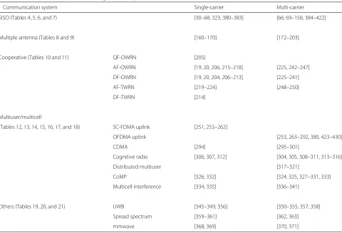
Table 1
Classification of papers on timing or carrier synchronization, 2010–2014
Communication system Single-carrier Multi-carrier
SISO (Tables 4, 5, 6, and 7) [30–68, 323, 380–383] [66, 69–158, 384–422]
Multiple antenna (Tables 8 and 9) [160–170] [172–203]
Cooperative (Tables 10 and 11) QF-OWRN [205]
AF-OWRN [19, 20, 206, 215–218] [225, 242–247]
DF-OWRN [19, 20, 204, 206–213] [225–241]
AF-TWRN [219–224] [248–250]
DF-TWRN [214]
Multiuser/multicell
(Tables 12, 13, 14, 15, 16, 17, and 18) SC-FDMA uplink [251, 253–262]
OFDMA uplink [253, 263–292, 380, 423–430]
CDMA [294] [295–301]
Cognitive radio [306, 307, 312] [304, 305, 308–311, 313–316]
Distributed multiuser [317–321]
CoMP [326, 332] [324, 325, 327–331, 333]
Multicell interference [334, 335] [336–341]
Others (Tables 19, 20, and 21) UWB [345–349, 356] [350–355, 357, 358]
Spread spectrum [359–361] [362, 363]
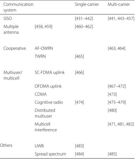
Table 2
Papers on the effect of timing or carrier synchronization
on the system performance, 2010–2014
Communication Single-carrier Multi-carrier system
SISO [431–442] [441, 443–457]
Multiple [458, 459] [460–462] antenna
Cooperative AF-OWRN [463, 464]
TWRN [465]
Multiuser/ SC-FDMA uplink [466] multicell
OFDMA uplink [467–472]
CDMA [473]
Cognitive radio [474] [475–479]
Distributed [480]
multiuser
Multicell [471, 481, 482]
interference
Others UWB [483]
Spread spectrum [484] [485]
(Section 2), (ii) MIMO (Section 3), (iii) cooperative
relay-ing (Section 4), (iv) multicell/multiuser (Section 5), and
(v) others (ultra-wide band (UWB) and spread spectrum)
communication networks (Section 6).
Each category is
split into single-carrier and multi-carrier (e.g., OFDM)
sys-tems
. For each category, we discuss the system model
for synchronization, the synchronization challenges, and
the state-of-the-art synchronization solutions and their
limitations. Future research directions and important
open problems are highlighted in Section 7. Finally,
Section 8 concludes this survey.
2
SISO systems
2.1
Single-carrier SISO communication systems
2.1.1
System model
In single-carrier SISO systems, a single antenna
transmit-ter communicates with a single antenna receiver and the
information is modulated over a single carrier.
The transmitter is assumed to communicate with
the receiver through an additive white Gaussian noise
(AWGN) or frequency-flat/frequency-selective fading
channel. At the receiver end, the effect of channel can
be
equalized
either in the time domain or the frequency
domain. Time domain equalization is a simple single tap
or multi-tap filter. In frequency domain equalization, also
referred to as single-carrier frequency domain
equaliza-tion (SC-FDE), frequency domain equalizaequaliza-tion is carried
out via the fast Fourier transform (FFT) and inverse fast
Fourier transform (IFFT) operations at the receiver.
2.1.2
Synchronization challenge
The received signal at the receiver is affected by a single
timing offset (TO) and a single-carrier frequency offset
(CFO). The receiver has to estimate these parameters and
compensate for their effects from the received signal in
order to decode it. The receiver may or may not have the
knowledge of CSI. In case of no CSI availability, a receiver
has to carry out CE in addition to TO or CFO estimation.
The estimation of TO and CFO can be achieved using
pilots or by blind methods. For pilot-based estimation, a
transmitter sends a known training sequence (TS) to the
receiver before sending the actual data. For blind
estima-tion, a receiver estimates the synchronization parameters
using unknown received data. Note that there exists
cou-pling between channel and CFO estimation and their
joint estimation is helpful to achieve the best estimation
accuracy for these parameters [19, 20].
2.1.3
Literature review
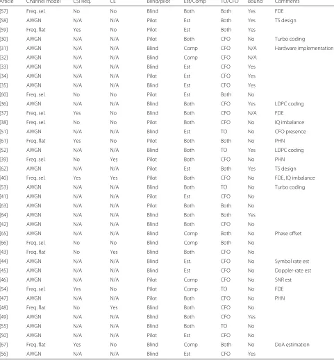
The summary of the research carried out to achieve
tim-ing and carrier synchronization in stim-ingle-carrier SISO
communication systems is given in Table 4:
1. The estimation or compensation of timing offset
alone and frequency offset alone is studied in [30–50]
and [51–56], respectively.
2. Joint timing and carrier synchronization is studied in
[57–67].
The categorized papers differ in terms of channel
model, channel estimation requirements, or pilot/training
requirements. They also differ in whether proposing
mation, compensation, joint channel estimation, or
esti-mating lower bound. Further details or differences among
these papers are provided in the last column of Table 4,
which further indicates whether any additional
param-eter such as phase noise (PHN), IQ imbalance,
signal-to-noise ratio (SNR) estimation, or direction of arrival
(DoA) estimation, is considered. Moreover, whether
train-ing sequence (TS) design or hardware implementation is
taken into consideration is also labeled in this table.
2.1.4
Summary
Table 3
List of common acronyms and abbreviations
Acronym Definition
AF Amplify and forward
AFD-DFE Adaptive frequency domain decision feedback equalizer
AOD Angle of departure
BER Bit error rate
CE Channel estimation
Comp Compensation
CFO Carrier frequency offset
CP Cyclic prefix
CSI Channel state information
DoA Direction of arrival
DF Decode and forward
DL Direct link
DLC-SFC Distributed linear convolutional space frequency code
DLC-STC Distributed linear convolutional space time coding
DSFBC Distributed space frequency block coding
DSTBC Distributed space time block coding
DSTC Distributed space time coding
Est Estimation
FBMC Filter bank multi-carrier
FDE Frequency domain equalization
FDMA Frequency division multiple access
FD-S3 Frequency domain-spread spectrum system
FFT Fast Fourier transform
Freq. flat Frequency flat
Freq. sel. Frequency selective
GD-S3 Gabor division-spread spectrum system
HetNet Heterogeneous network
IFFT Inverse fast Fourier transform
IFO Integer frequency offset
IQ In-phase quadrature-phase
IR Impulse radio
MAI Multiple access interference
MB-OFDM Multiband-OFDM
MC Multi-carrier
MCFOs Multiple carrier frequency offsets
MISO Multiple-input single-output
MTOs Multiple timing offsets
N/A Not applicable
OSTBC Orthogonal space time block coding
OWRN One-way relaying network
PHN Phase noise
PUs Primary users
req. Required
Rx Receiver
SC Single carrier
Table 3
List of common acronyms and abbreviations
(Continued)
SCO Sampling clock offset
SDR Software defined radio
SFBC Space frequency block coding
SFCC Space frequency convolution coding
SFO Sampling frequency offset
SIMO Single-input multiple-output
STC Space time coding
TD-LTE Time division Long-Term Evolution
TH Time hopping
TR-STBC Time reversal space time block code
TO Timing offset
TS Training sequence
TWR Two-way ranging
TWRN Two-way relaying network
Tx Transmitter
UFMC Universal filtered multi-carrier
WSN Wireless sensor network
in Table 4 with similar assumptions to make clear how the
state of the art is advancing.
Since it is desired to implement both estimation and
compensation of timing and carrier frequency offsets,
a few research works have considered such problems
assuming AWGN [63, 64], frequency flat [61], and
fre-quency selective channels [57]. The future work in this area
may consider [57, 61, 63, 64] as baseline research work
and further develop for more efficient estimation and
compensation techniques and hardware implementation.
2.2
Multi-carrier SISO communication systems
2.2.1
System model
Table 4
Summary of synchronization research in single-carrier SISO communication systems
Article Channel model CSI Req. CE Blind/pilot Est/Comp TO/CFO Bound Comments
[57] Freq. sel. No No Blind Both Both Yes FDE
[58] AWGN N/A N/A Pilot Est Both Yes TS design
[59] Freq. flat Yes No Pilot Est Both Yes
[30] AWGN N/A N/A Pilot Both CFO No Turbo coding
[31] AWGN N/A N/A Blind Comp CFO N/A Hardware implementation
[32] AWGN N/A N/A Blind Comp CFO N/A
[33] AWGN N/A N/A Blind Est CFO Yes
[34] AWGN N/A N/A Pilot Est CFO Yes
[35] AWGN N/A N/A Blind Est CFO Yes
[60] Freq. sel. No No Pilot Est Both No
[36] AWGN N/A N/A Blind Both CFO Yes LDPC coding
[37] Freq. sel. Yes No Blind Both CFO N/A FDE
[38] Freq. sel. No No Pilot Both CFO No IQ imbalance
[51] AWGN N/A N/A Blind Est TO No CFO presence
[61] Freq. flat Yes No Pilot Both Both No PHN
[52] AWGN N/A N/A Blind Both TO Yes LDPC coding
[39] Freq. sel. No Yes Pilot Both CFO No PHN
[62] AWGN N/A N/A Pilot Est Both Yes TS design
[40] Freq. sel. Yes Yes Pilot Both CFO No FDE, IQ imbalance
[53] AWGN N/A N/A Blind Both TO No Turbo coding
[41] AWGN N/A N/A Pilot Est CFO No
[63] AWGN N/A N/A Pilot Both Both No
[64] AWGN N/A N/A Blind Both Both Yes
[42] AWGN N/A N/A Blind Both CFO No
[65] AWGN N/A N/A Blind Comp Both No Phase offset
[66] Freq. sel. No No Blind Comp Both No
[43] Freq. flat No Yes Blind Both CFO No
[44] AWGN N/A N/A Blind Est. CFO No Symbol rate est
[45] AWGN N/A N/A Blind Est CFO No Doppler-rate est
[46] AWGN N/A N/A Pilot Comp CFO No SNR est
[54] Freq. sel. Yes No Pilot Comp TO No FDE
[47] AWGN N/A N/A Pilot Both CFO No PHN
[48] Freq. flat No Yes Blind Both CFO No
[49] AWGN N/A N/A Blind Both CFO Yes
[55] AWGN N/A N/A Blind Both TO No
[50] AWGN N/A N/A Pilot Est CFO No
[67] Freq. flat Yes No Blind Comp Both No DoA estimation
[56] AWGN N/A N/A Blind Est CFO Yes
2.2.2
Synchronization challenge
In OFDM systems, the presence of TO affects the system
performance in a different ways as compared to
single-carrier systems:
1. If the TO lies within the ISI-free region of the cyclic
prefix, the orthogonality among the subcarriers is not
destroyed and the timing offset only introduces a
phase rotation in every subcarrier symbol. For a
coherent system, this phase rotation is compensated
for by the channel equalization scheme, which views
it as a channel-induced phase shift.
Thus, the objective of timing synchronization in OFDM
systems, unlike in single-carrier systems, is to identify the
start of an OFDM symbol within the ISI-free region of the
cyclic prefix.
The presence of CFO in OFDM systems attenuates
the desired signal and introduces ICI since the
modu-lated carrier is demodumodu-lated at an offset frequency at the
receiver side. In OFDM systems, CFO is usually
repre-sented in terms of subcarrier spacings and can be divided
into an integer part (integer number less than the total
number of subchannels) and a fractional part (within
±
12of subcarrier spacing). If the CFO is greater than the
sub-carrier spacing, a receiver has to estimate and compensate
for both the integer and fractional parts of the normalized
CFO.
The synchronization in OFDM systems can be
per-formed either in the time domain or the frequency domain
depending upon whether the signal processing is executed
pre-FFT or post-FFT at the receiver, respectively.
2.2.3
Literature review
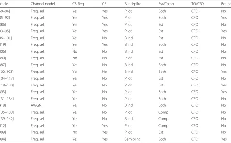
The summary of the research carried out to achieve
car-rier synchronization, timing synchronization, and joint
timing and carrier synchronization in multi-carrier SISO
communication systems is given in Tables 5, 6, and 7,
respectively. Their details are given below.
1. Carrier synchronization:
The papers studying carrier synchronization in
multi-carrier SISO communication systems are
listed in Table 5. It can be observed that there are
groups of papers which consider the same channel
model and the same requirement for CSI and
training. Also, they consider the same problem in
terms of estimation or compensation. In the
following, we describe how these papers differ
within their respective groups.
(a)
Pilot-based CFO estimation and
compensation with channel estimation:
The papers here can be grouped into two
categories. The first group does not provide
an estimation error lower bound [68–84]. In
addition to carrier synchronization, [68]
proposes to achieve seamless service in
vehicular communication and also considers
road side unit selection; [69] considers CFO
tracking assuming constant modulus-based
signaling; [70] considers concatenated
precoded OFDM system, [71] proposes
MMSE-based estimation; [72] proposes
hard-decision-directed-based CFO tracking;
[73] considers phase-rotated conjugate
Table 5
Summary of research in multi-carrier SISO communication systems considering carrier synchronization
Article Channel model CSI Req. CE Blind/pilot Est/Comp TO/CFO Bound
[68–84] Freq. sel. Yes Yes Pilot Both CFO No
[85–92] Freq. sel. Yes Yes Pilot Both CFO Yes
[386] Freq. sel. Yes Yes Pilot Est CFO No
[93–95] Freq. sel. Yes Yes Pilot Est CFO Yes
[96–101] Freq. sel. Yes No Blind Est CFO No
[419] Freq. sel. Yes Yes Blind Both CFO No
[406] Freq. sel. No No Blind Est CFO No
[380] Freq. sel. No No Pilot Est CFO No
[387] Freq. sel. Yes No Blind Both CFO No
[102, 103] Freq. sel. Yes No Blind Both CFO Yes
[104–117] Freq. sel. Yes No Pilot Est CFO No
[118–130] Freq. sel. Yes No Pilot Est CFO Yes
[393] Freq. sel. Yes No Pilot Both CFO Yes
[131–134] Freq. sel. Yes No Pilot Both CFO No
[418] AWGN Yes No Blind Both CFO No
[135–138] Freq. sel. Yes No Pilot Comp CFO No
[139–142] Freq. sel. Yes No Blind Comp CFO No
[412] Freq. sel. Yes Yes Pilot Comp CFO No
[389] Freq. sel. No Yes Pilot Est CFO No
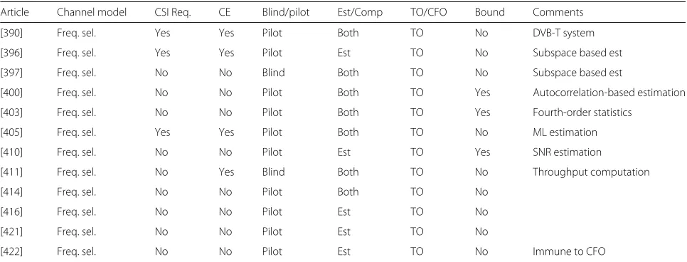
Table 6
Summary of research in multi-carrier SISO communication systems considering timing synchronization
Article Channel model CSI Req. CE Blind/pilot Est/Comp TO/CFO Bound Comments
[390] Freq. sel. Yes Yes Pilot Both TO No DVB-T system
[396] Freq. sel. Yes Yes Pilot Est TO No Subspace based est
[397] Freq. sel. No No Blind Both TO No Subspace based est
[400] Freq. sel. No No Pilot Both TO Yes Autocorrelation-based estimation
[403] Freq. sel. No No Pilot Both TO Yes Fourth-order statistics
[405] Freq. sel. Yes Yes Pilot Both TO No ML estimation
[410] Freq. sel. No No Pilot Est TO Yes SNR estimation
[411] Freq. sel. No Yes Blind Both TO No Throughput computation
[414] Freq. sel. No No Pilot Both TO No
[416] Freq. sel. No No Pilot Est TO No
[421] Freq. sel. No No Pilot Est TO No
[422] Freq. sel. No No Pilot Est TO No Immune to CFO
transmission and receiver feedback; [74]
considers hardware implementation with IQ
imbalance and power amplifier nonlinearity;
[75] considers hexagonal multi-carrier
transmission system and a doubly dispersive
channel; [76] considers maximum a
posteriori expectation-maximization
(MAP-EM)-based Turbo receiver; [77]
considers an FBMC system; [78] considers
aerial vehicular communication; [79]
proposes noise variance estimation and
considers EM algorithm; [80] considers SFO
estimation; [81] considers hardware
implementation, [82] proposes estimation of
the CFO over a wide range of offset values;
[83] considers IQ imbalance and phase noise
distortion; and [84] considers Doppler
spread in a mobile OFDM system.
The second group of papers provides an
estimation error lower bound on obtaining
the CFO [85–92]. In addition to carrier
synchronization, [85] considers IQ
imbalance, [87] proposes an extended
Kalman filter (EKF)-based estimator in the
presence of phase noise, [88] proposes an
ML estimator and considers an FBMC
system, [89] considers SFO estimation and
synchronization, [90] considers ML based
frequency tracking, and [91] considers IQ
imbalance and its estimation.
(b)
Pilot-based CFO estimation with channel
estimation:
The papers [93–95] fall under this category.
In addition to carrier synchronization, [94]
proposes computationally efficient, single
training sequence-based least squares
estimation, [93] considers doubly selective
channel estimation, and [95] proposes an
EM-based ML estimator and also considers
the presence of phase noise.
(c)
Blind CFO estimation with no channel
estimation:
Table 7
Summary of research in multi-carrier SISO communication systems considering joint timing and carrier synchronization
Article Channel model CSI Req. CE Blind/Pilot Est/Comp TO/CFO Bound
[143–147] Freq. sel. Yes Yes Pilot Both Both No
[409] Freq. sel. Yes Yes Pilot Est Both No
[402] Freq. sel. Yes No Pilot Both Both Yes
[148, 149, 384] Freq. sel. Yes No Blind Est Both Yes
[150, 151] Freq. sel. Yes No Pilot Both Both No
[415] AWGN N/A N/A Pilot Both Both No
[152–155] Freq. sel. Yes No Pilot Est Both No
[156–158] Freq. sel. Yes No Pilot Est Both Yes
[385] Freq. sel. Yes No Blind Both Both No
The papers here can be grouped into two
categories. The first group does not provide
an estimation lower bound [96–101]. In
addition to carrier synchronization, [96]
considers a cognitive radio network and the
algorithm applies even if timing offset is
unknown, [97] considers time-varying
channels and Doppler frequency, [98, 99]
consider constant modulus-based signaling,
[100] considers cyclic correlation-based
estimation, the estimator proposed by [101]
is based on minimum reconstruction error,
and [92] proposes an EM based estimator
considering very high mobility.
The second group of papers provides an error
lower bound on CFO estimation [102, 103].
In addition to carrier synchronization, [102]
proposes a Viterbi-based estimator and
[103] proposes CFO estimation using single
OFDM symbol and provides closed-form
expression for the CFO estimate using
property of the cosine function.
(d)
Pilot-based CFO estimation with no channel
estimation:
The papers here can be grouped into two
categories. The first group of papers does
not provide an estimation error lower bound
[104–117]. In addition to carrier
synchronization, the CFO estimation
algorithm proposed by [104] is valid even if
timing offset and channel length is unknown;
the algorithm proposed by [105] estimates
integer frequency offset; the algorithm
proposed by [106] estimates sampling
frequency offset in addition to CFO; [107]
estimates IFO for OFDM-based digital radio
mondiale plus system; [108] considers IQ
imbalance and direct-conversion receivers;
[109] considers CFO tracking in digital video
broadcasting (DVB-T) system; [110]
proposes ML-based estimation; [111, 113]
propose IFO estimation with cell sector
identity detection in Long-Term Evolution
systems; [112] considers IQ imbalance and
hardware implementation; [114] also
considers SFO estimation; [115] proposes
ML-based estimation and considers the
design of pilot pattern, the estimation
algorithm in [116] is robust to the presence
of the Doppler shift; and [117] considers IQ
imbalance and its estimation.
The second group of papers provides an error
lower bound on CFO estimation [118–130].
In addition to carrier synchronization, [118]
derives CRLB for the general case where any
kind of subcarriers, e.g., pilot, virtual, or data
subcarriers, may exist; [119] considers
eigenvalue-based estimation; [120] considers
subspace-based channel estimation with
hardware implementation and SNR
detection; [121] considers IFO estimation an
d training sequence design; [122] considers
Gaussian particle filtering-based estimation;
[123] proposes both IFO and FFO
estimation while also considering IQ
imbalance and a direct conversion receiver
structure; [124] considers SFO estimation
while proposing ML-based estimation; [125]
proposes multiple signal classification or a
subspace-based estimation method; [126]
proposes an estimator based on the
space-alternating generalized
expectation-maximization (SAGE)
algorithm and considers IQ imbalance; [127]
proposes SNR and noise power estimation;
[128, 129] consider IQ imbalance; and [130]
considers doubly selective fading channels.
(e)
Pilot-based CFO estimation and
compensation with no channel estimation:
The papers [131–134] fall under this category.
In addition to carrier synchronization, [131]
proposes training sequence design in
DVB-T2 system, [132] considers frequency
domain pilot signaling, [133] also considers
SFO estimation, and [134] considers IQ
imbalance and its estimation.
(f)
Pilot-based CFO compensation with no
channel estimation:
The papers [135–138] fall under this
category. The differences among them are
that in addition to carrier synchronization,
[136] proposes repeated correlative coding
for mitigation of ICI, [135] proposes training
sequence design, [137] considers cell identifi
cation in Long-Term Evolution (LTE) system,
and [138] considers detection of primary
synchronization signal in LTE systems.
(g)
Blind CFO compensation with no channel
estimation:
2. Timing synchronization:
Compared to the categorized papers for carrier
synchronization in Table 5, the categorized papers
for timing synchronization in Table 6 have greater
similarity. The major differences are found in terms
of channel estimation requirement, pilot/training
requirement, and lower bounds on the estimation
performance. Further details are provided in the last
column of Table 6, which also indicates if any
additional parameter, e.g., SNR estimation, is
considered.
3. Joint timing and carrier synchronization:
The papers studying joint timing and carrier
synchronization in multi-carrier SISO
communication systems are listed in Table 7. It can
be observed that there are groups of papers which
consider the same channel model and the same
requirement for CSI and training. Also, they further
consider the same problem in terms of estimation or
compensation. In the following, we describe how
these papers differ within their respective groups.
(a)
Pilot-based TO and CFO estimation and
compensation with channel estimation:
The papers [143–147] fall under this
category. In addition to joint timing and
carrier synchronization, [143] considers IFO
estimation while considering residual timing
offset, [144] considers hardware
implementation, [145] considers FBMC
system, [146] considers offset-QAM
modulation, and [147] considers decision
directed-based estimation.
(b)
Blind TO and CFO estimation with no
channel estimation:
The papers [148, 149] fall under this
category. In addition to joint timing and
carrier synchronization, [148] considers
digital video broadcasting (DVB-T2)
standard and [149] proposes ML estimation
with a time-domain preamble.
(c)
Pilot-based TO and CFO estimation and
compensation with no channel estimation:
The papers [150, 151] fall under this
category. In addition to joint timing and
carrier synchronization, [150] considers
time domain synchronous (TDS)-OFDM
system which replaces cyclic prefix with a
pseudo noise (PN) and thus proposes
PN-correlation-based synchronization, and
[151] considers hardware implementation.
(d)
Pilot-based TO and CFO estimation with no
channel estimation:
The first group of papers does not provide
an estimation error lower bound [152–155].
The differences among them are that in
addition to joint timing and carrier
synchronization, CFO estimation in [152]
applies to a wide CFO range, i.e.,
±
1
/
2
the
total number of subcarrier widths; [153]
considers phase noise (PN)-sequence-based
preamble; [154] considers digital video
broadcasting (DVB-T2) system; and [155]
considers blind cyclic prefix length in their
algorithm.
The second group of papers provides an
estimation error lower bound [156–158]. In
addition to joint timing and carrier
synchronization, [156] considers doubly
selective channel, [157] considers hexagonal
multi-carrier transmission system, and [158]
proposes training sequence design.
2.2.4
Summary
Timing and carrier synchronization for multi-carrier
SISO communication systems is still an ongoing topic of
research, as evidenced by the large number of published
papers. In particular, there is a major emphasis on
accu-rate CFO estimation for different types of systems and
often in conjunction with RF impairments such as phase
noise and IQ imbalance.
Few recent research works have considered the
prac-tical problem of both estimation and compensation of
timing and carrier frequency offsets in the presence
of channel impairments [143–147]. Particularly, [147]
considers known symbol padding (KSP)-OFDM system,
[143, 144] also introduces a hardware co-simulation
platform, [145] considers an FMBC system, and [146]
con-siders an OQAM-OFDM system. The authors in [143]
only consider integer frequency offsets and the particular
work may be extended considering both integer and
frac-tional frequency offsets. The works of [143–147] can be
considered as a baseline reference for further extension in
the relevant system models.
3
Multi-antenna systems
3.1
Single-carrier multi-antenna communication systems
3.1.1
System model
A space-time MIMO decoder can be used to decode
the signal from multiple antenna streams. On the other
hand, in order to achieve diversity gain, the same
sym-bol weighted by a complex scale factor may be sent over
each transmit antenna. This latter scheme is also referred
to as MIMO beamforming [159]. Depending on the
spa-tial distance between the transmit or receive antennas,
which may differ for line-of-sight (LOS) and non-LOS
propagation, the antennas may be equipped with either
their own oscillators or use the same oscillator.
Depending on the number of antennas at the
transmit-ter and the receiver, multi-antenna systems can be further
categorized into MIMO systems, multiple-input
single-output (MISO) systems, or single-input multiple-single-output
(SIMO) systems. Further, if the antennas at the
trans-mitter side are not co-located at a single device, such a
system is referred to as a distributed-MIMO system, i.e.,
multiple distributed transmitters simultaneously
commu-nicate with a single multi-antenna receiver.
3.1.2
Synchronization challenge
In multi-antenna systems, multiple signal streams arrive
at the receive antenna from different transmit antennas
resulting in
multiple timing offsets (MTOs)
. In some
spe-cial cases, multiple timing offsets actually reduce to a
sin-gle timing offset, e.g., if multiple antennas are co-located
at a single transmitter device, then the transmit filters can
be synchronized easily and the multiple signal streams
arriving at the receive antenna experience approximately
the same propagation delay.
If the transmit antennas are fed through independent
oscillators, the received signal at the receive antenna is
affected by
multiple carrier frequency offsets (MCFOs)
because of the existence of independent frequency offset
between each transmit antenna oscillator and the receive
antenna oscillator. On the other hand, if the transmit
antennas are equipped with a single oscillator, the received
signal at the receive antenna is affected by a single
fre-quency offset. Thus, each receive antenna has to estimate
and compensate for a single or multiple timing and
fre-quency offsets, depending on the system model
assump-tions including Doppler fading.
In the case of distributed antenna systems, the receiver
has to estimate and compensate for multiple CFOs and
multiple TOs because each distributed transmit antenna
is equipped with its own oscillator and multiple signal
streams arriving at the receive antenna experience
differ-ent propagation delays. Thus, in practice, the number of
distributed antennas may need to be limited to avoid
syn-chronization and pilot overhead associated with obtaining
multiple CFOs and TOs.
3.1.3
Literature review
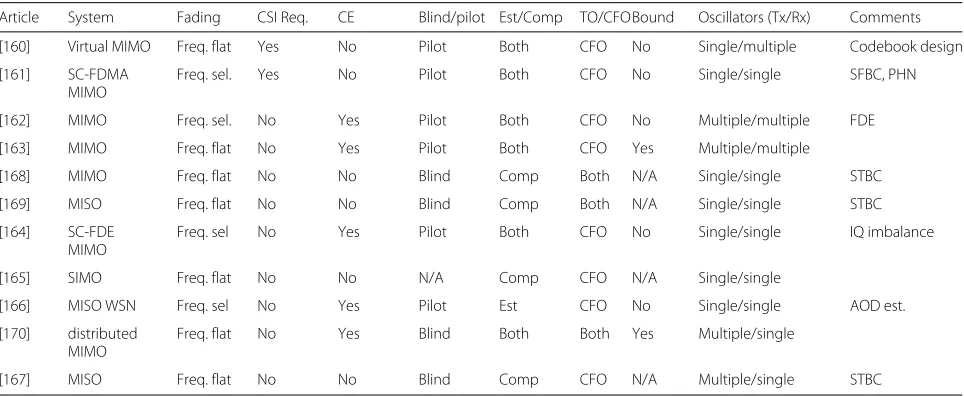
The summary of the research carried out to achieve
tim-ing and carrier synchronization in stim-ingle-carrier
multi-antenna communication systems is given in Table 8:
1. The estimation or compensation of CFO alone is
studied in [160–167].
2. The joint timing and carrier synchronization is
studied in [168–170].
The categorized papers differ in terms of channel model,
channel estimation requirement, or pilot/training
require-ment. They also differ in terms of proposing estimation,
compensation, joint channel estimation, or estimation
lower bound. Further details or differences are provided
in the last column of Table 4, which indicates if any
Table 8
Summary of synchronization research in single-carrier multi-antenna communication systems
Article System Fading CSI Req. CE Blind/pilot Est/Comp TO/CFOBound Oscillators (Tx/Rx) Comments
[160] Virtual MIMO Freq. flat Yes No Pilot Both CFO No Single/multiple Codebook design
[161] SC-FDMA MIMO
Freq. sel. Yes No Pilot Both CFO No Single/single SFBC, PHN
[162] MIMO Freq. sel. No Yes Pilot Both CFO No Multiple/multiple FDE
[163] MIMO Freq. flat No Yes Pilot Both CFO Yes Multiple/multiple
[168] MIMO Freq. flat No No Blind Comp Both N/A Single/single STBC
[169] MISO Freq. flat No No Blind Comp Both N/A Single/single STBC
[164] SC-FDE MIMO
Freq. sel No Yes Pilot Both CFO No Single/single IQ imbalance
[165] SIMO Freq. flat No No N/A Comp CFO N/A Single/single
[166] MISO WSN Freq. sel No Yes Pilot Est CFO No Single/single AOD est.
[170] distributed MIMO
Freq. flat No Yes Blind Both Both Yes Multiple/single
additional parameter, e.g., phase noise (PHN), IQ
imbal-ance, or direction of arrival (DoA) estimation, is
con-sidered or if space-time block coding (STBC), space
frequency block coding (SFBC), or codebook design is
considered.
3.1.4
Summary
Synchronization in single-carrier multi-antenna
commu-nication systems has not received as much attention
com-pared to synchronization in multi-carrier multi-antenna
communication systems. This may not be surprising since
the latter is adopted in current wireless cellular standards.
Still, single-carrier multi-antenna communication has got
its importance in microwave backhaul links [171]. The
important problem of joint estimation and
compensa-tion of MTOs and MCFOs has been considered in [170].
The authors assume pilot-free systems to propose blind
synchronization. Generally, performance improvement is
expected in the presence of training-based estimation and
compensation. This, along with hardware implementation
of the relevant algorithms, can be the subject of possible
future extensions.
3.2
Multi-carrier multi-antenna communication systems
3.2.1
System model
In multi-carrier multi-antenna systems, the information
at each antenna is modulated over multiple carriers. Thus,
apart from the IFFT/CP addition and CP removal/FFT
operations at each transmit and receive antennas,
respec-tively, the system model for multi-carrier multi-antenna
communication systems is similar to the one described
for single-carrier multi-antenna systems presented in
Section 3.1.1.
3.2.2
Synchronization challenge
Similar to single-carrier multi-antenna systems, the
sig-nal arriving at the receive antenna can potentially be
affected by multiple TOs and multiple CFOs, when the
transmit antennas are fed by different oscillators and are
distant from one another. Due to multiple carriers, the
presence of multiple TOs and multiple CFOs results in
strong ISI and ICI. The synchronization challenge is to
jointly estimate and compensate for the effect of
mul-tiple TOs and mulmul-tiple CFOs in order to mitigate ISI
and ICI and decode the signal from multiple antenna
streams.
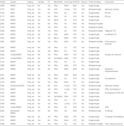
3.2.3
Literature review
The summary of the research carried out to achieve
tim-ing and carrier synchronization in stim-ingle-carrier
multi-antenna communication systems is given in Table 9:
1. The estimation or compensation of TO and CFO
alone is studied in [172–174] and [175–198],
respectively.
2. The joint timing and carrier synchronization is
studied in [199–203].
The number of oscillators considered by different
papers at the transmitter and receiver, respectively, are
given under the “Tx/Rx Oscillator” column. The
catego-rized papers differ in terms of channel model, channel
estimation requirement, or pilot/training requirement.
They also differ in proposing estimation, compensation,
joint channel estimation, or estimation lower bound.
Further details or differences are provided in the last
column of Table 9, which indicates if additional
param-eters, e.g., phase noise or IQ imbalance, are considered
or if STBC, SFBC, coding, or hardware implementation is
considered.
3.2.4
Summary
Compared to the estimation of single TO and single
CFO, estimation of MTOs and MCFOs is more
challeng-ing, due to pilot design issues, overhead, pilot
contam-ination problem, complexity, and non-convex nature of
optimization problems. Considering multiple oscillators
at the transceiver, joint estimation of MTOs and MCFOs
has been considered in [200, 203] only. Particularly, the
authors in [203] propose a compact TS design.
How-ever, both papers, [200, 203], do not consider channel
estimation as it may help in improving the estimation
performance of synchronization impairments, and
fur-ther, they do not suggest algorithms for compensation of
MTOs and MCFOs. Though joint estimation and
com-pensation of timing and carrier frequency offset has been
studied, e.g., in [199, 202], however, their system model
consider single oscillator at the transceiver. The
short-comings in the above key papers can be the subject of
possible future research.
4
Cooperative communication systems
In cooperative communication systems, the information
transmission between the two communicating nodes is
accomplished with the help of an intermediate relay. Let
us assume a general scenario with the presence of
multi-ple relays. There are two important types of cooperative
communication networks:
•
One-way relaying network (OWRN), where
information transmission occurs in one direction via
intermediate relays.
•
Two-way relaying network (TWRN), where
information transmission occurs simultaneously in
both directions and both nodes exchange their
information with the help of intermediate relays.
Table 9
Summary of synchronization research in multi-carrier multi-antenna communication systems
Article System Fading CSI Req. CE Blind/Pilot Est/Comp TO/CFO Bound Tx/Rx Oscillator Comments
[199] MIMO Freq. sel. No Yes Pilot Both Both Yes Single/single
[175] MISO Freq. sel. Yes No N/A Comp CFO N/A Multiple/single Alamouti coding
[176] MISO Freq. sel. Yes No Pilot Est CFO No Single/single IFO est.
[177] MISO Freq. sel. Yes No Pilot Est CFO No Single/single IFO est.
[178] MIMO Freq. sel. No No Blind Est CFO No Single/single
[200] MIMO Freq. sel. No No Pilot Est Both No Multiple/multiple
[179] MIMO Freq. sel. No Yes Pilot Est CFO No Multiple/multiple
[180] MIMO Freq. sel. No Yes Pilot Est CFO Yes Multiple/multiple Algebraic STC
[181] MIMO Freq. sel. No Yes Pilot Both CFO Yes Single/single insufficient CP
[182] MIMO Freq. sel. No Yes Blind Both CFO Yes Single/single
[183] MIMO Freq. sel. No Yes Pilot Both CFO No Multiple/multiple Time-varying channel
[184] MIMO Freq. sel. No Yes Pilot Est CFO Yes Single/single
[185] MIMO Freq. sel. No Yes Blind Est CFO Yes Single/single
[186] Coded MIMO Freq. sel. No Yes Pilot Both CFO Yes Single/single Doubly sel. channel
[187] Coded MIMO Freq. sel. No Yes Semiblind Both CFO No Single/single
[172] MIMO Freq. sel. No Yes Pilot Est TO No Single/single
[188] MIMO Freq. sel. No Yes Pilot Both CFO Yes Multiple/single
[201] MIMO Freq. sel. No No Pilot Both Both No Single/single Hardware
implementation
[202] MIMO Freq. sel. No Yes Pilot Both Both Yes Single/single
[189] MIMO Freq. sel. No Yes Pilot Est CFO Yes Single/single IQ imbalance
[173] MIMO Freq. sel. No Yes Pilot Both TO No Single/single
[190] distributed MISO Freq. flat Yes No N/A Comp CFO N/A Multiple/single Alamouti coding
[191] MIMO Freq. sel. No Yes Pilot Comp CFO No Single/single SFBC, IQ imbalance
[192] MIMO Freq. sel. No Yes Pilot Est CFO No Single/single IQ imbalance, PHN, SFO
[193] MIMO Freq. sel. Yes No Semiblind Both CFO No Single/single
[174] MIMO Freq. flat No Yes Pilot Est TO Yes Single/single
[194] MIMO Freq. sel. No Yes Pilot Comp CFO No Single/single
[195] coded MIMO Freq. sel. No Yes Pilot Est CFO Yes Single/single STBC
[203] distributed MIMO
Freq. sel. No No Pilot Est Both No Multiple/single TS design
[196] MIMO Freq. sel. No Yes Pilot Both CFO Yes Single/single TS design, IQ imbalance
[197] MIMO Freq. sel. Yes No Pilot Both CFO No Single/single
[198] MIMO Freq. sel. Yes Yes Pilot Est CFO No Multiple/multiple Time-varying channel
(DF) and (ii) amplify-and-forward (AF) operation. In DF
mode, the relays decode the received signal and forward
the decoded signal to the intended destination node(s).
In AF mode, the relays do not decode the received
message and simply amplify and forward the received
signal.
In the following subsections, we review the recent
liter-ature that deals with timing and carrier synchronization
in single-carrier and multi-carrier cooperative
communi-cation systems.
4.1
Single-carrier cooperative communication systems
subsections, we provide separate literature reviews for
synchronization in AF-OWRN, AF-TWRN, DF-OWRN,
and DF-TWRN for single-carrier communication
sys-tems.
4.1.1
Decode-and-forward one-way relaying network
System model
The communication generally takes place
in two phases. During the first phase, the source
trans-mits the information to the relays. During the second
phase, the relays decode the received signal and forward it
to the destination. Typically, it is assumed that the direct
communication link between the source and the
destina-tion is absent or blocked due to some obstacles. However,
in general, there could be a direct communication link
between them. In such a case, the destination also hears
the source message during the first phase and coherently
combines it with the message received during the second
phase.
Synchronization challenge
In DF-OWRN, during the
first phase of the two-phase communication process, the
synchronization between the source and the relays or
between the source and the destination (in the presence
of direct link) is achieved by estimating and
compensat-ing for a scompensat-ingle TO and CFO between the source and
each relay or between the source and the destination (in
the presence of direct link). During the second phase, the
synchronization between the relays and the destination is
achieved by estimating and compensating for the
multi-ple TOs and multimulti-ple CFOs between the multimulti-ple relays
and the destination. Note that in the case of a single relay,
only a single TO and a single CFO are required to be
esti-mated and compensated for at the destination during the
second communication phase. Increasing the number of
relays raises the challenge of pilot design and estimation
overhead.
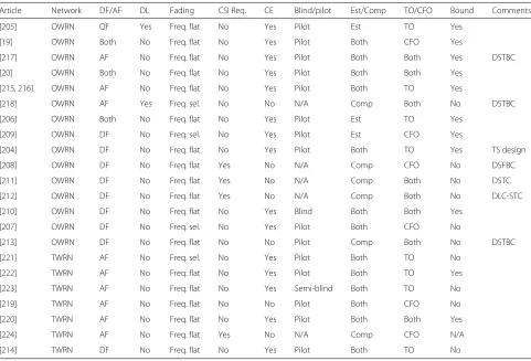
Literature review
The summary of the research
car-ried out to achieve timing and carrier synchronization in
single-carrier DF-OWRN is given in Table 10:
1. Estimation or compensation of timing offsets alone
and frequency offsets alone is studied in [204–206]
and [19, 207–209], respectively.
2. Joint timing and carrier synchronization is studied in
[20, 210–213].
Further details or differences are provided in the last
column of Table 10, which indicates whether STBC, SFBC,
or training sequence (TS) design is considered.
4.1.2
Decode-and-forward two-way relaying network
System model
TWRNs allow for more bandwidth
effi-cient use of the available spectrum since they allow
for simultaneous information exchange between the two
nodes. In TWRNs, it is usually assumed that there is
no direct communication link between the two nodes.
During the first phase of the two-phase communication
process, the information arrives at the relays from the
two nodes. The signals from the two nodes are
superim-posed at the relays. During the second phase, the relays
decode the exclusive OR (XOR) of the bits from the
received superimposed signal and then broadcast a
sig-nal constructed from the XOR of the bits back to the two
nodes [214].
Synchronization challenge
The synchronization
chal-lenge during the first communication phase of DF-TWRN
is unlike that for DF-OWRN. In DF-TWRN, the relays
receive the superimposed signals from the two nodes
during the first communication phase. Thus, unlike
DF-OWRN, the received signal at each relay during the first
communication phase is a function of two TOs and two
CFOs, which need to be jointly estimated and
compen-sated for in order to decode the modulo-2 sum of the
bits from the two nodes. The synchronization challenge
during the second communication phase of DF-TWRN is
similar to that described for DF-OWRN in Section 4.1.1.
Another challenge for TWRN is the pilot design in the
presence of self-interference at the relay node.
Literature review
A summary of the research carried out
to achieve timing and carrier synchronization in
single-carrier DF-TWRN is given in Table 10. There is only one
paper in the last 5 years that falls in this category and
pro-poses joint estimation and compensation of timing offsets
[214]. Most of the research has considered AF relaying for
TWRN due to its implementation advantages.
4.1.3
Amplify-and-forward one-way relaying network
System model
The system model for AF-OWRN is
sim-ilar to that of Section 4.1.1 for DF-OWRN. However,
instead of DF operation, the relays amplify and forward
the source information.
Table 10
Summary of synchronization research in single-carrier cooperative communication systems
Article Network DF/AF DL Fading CSI Req. CE Blind/pilot Est/Comp TO/CFO Bound Comments
[205] OWRN QF Yes Freq. flat No Yes Pilot Est TO Yes
[19] OWRN Both No Freq. flat No Yes Pilot Both CFO Yes
[217] OWRN AF No Freq. flat No Yes Pilot Both Both Yes DSTBC
[20] OWRN Both No Freq. flat No Yes Pilot Both Both Yes
[215, 216] OWRN AF No Freq. flat No Yes Pilot Both TO Yes
[218] OWRN AF Yes Freq. sel. No No N/A Comp Both No DSTBC
[206] OWRN Both No Freq. flat No Yes Pilot Est TO Yes
[209] OWRN DF No Freq. sel. No Yes Pilot Est CFO Yes
[204] OWRN DF No Freq. flat No Yes Pilot Both TO Yes TS design
[208] OWRN DF No Freq. flat Yes No N/A Comp CFO No DSFBC
[211] OWRN DF No Freq. flat Yes No N/A Comp Both No DSTC
[212] OWRN DF No Freq. flat Yes No N/A Comp Both No DLC-STC
[210] OWRN DF No Freq. flat No Yes Blind Both Both Yes
[207] OWRN DF No Freq. sel. No Yes Pilot Both CFO No
[213] OWRN DF No Freq. flat No No Pilot Comp Both No DSTBC
[221] TWRN AF No Freq. sel. No Yes Pilot Both TO No
[222] TWRN AF No Freq. flat No Yes Pilot Both TO Yes
[223] TWRN AF No Freq. flat No Yes Semi-blind Both TO No
[219] TWRN AF No Freq. flat No No Pilot Both CFO No
[220] TWRN AF No Freq. flat No Yes Pilot Both Both Yes
[224] TWRN AF No Freq. flat Yes No N/A Comp CFO N/A
[214] TWRN DF No Freq. flat No Yes Pilot Both TO No
Literature review
The summary of the research
car-ried out to achieve timing and carrier synchronization in
single-carrier AF-OWRN is given in Table 10:
1. Estimation or compensation of timing offset alone
and frequency offset alone is studied in [206, 215, 216]
and [19], respectively.
2. Joint timing and carrier synchronization is studied in
[20, 217, 218].
4.1.4
Amplify-and-forward two-way relaying network
System model
During the first phase, similar to
DF-TWRN, the relays receive the superimposed signal from
the two nodes. During the second phase, the relays
amplify and broadcast the superimposed signal back to
the two nodes [214].
Synchronization challenge
In AF-TWRN, when the
relays receive the superimposed signals from the two
nodes during the first communication phase, each relay
only needs to carry out timing synchronization, i.e.,
estimate and compensate for the TOs between the
two nodes and the relay [219, 220]. The reason will
be explained shortly. During the second
communica-tion phase, the relays amplify and broadcast the
time-synchronized version of the superimposed signal. Each
node then needs to estimate and compensate for the
MTOs between the relays and itself and the sum of the
multiple CFOs from the other node-to-relays-to-itself.
Note that each node in this case does not need to
esti-mate and compensate for the multiple CFOs from itself
to relays to the other node because the effect of CFOs
between itself and the relays during the first
communica-tion phase is canceled by the effect of CFOs between the
relays and itself during the second communication phase
due to the use of the same oscillators [219, 220]. Due to
this very reason, the authors in [219, 220] propose to only
perform timing synchronization at the relay nodes during
the first communication phase in AF-TWRN.
Literature review
The summary of the research
car-ried out to achieve timing and carrier synchronization in
single-carrier AF-OWRN is given in Table 10:
2. The joint timing and carrier synchronization is
studied by [220].
4.1.5
Summary
In single-carrier cooperative communication systems, few
recent research works have considered the important
problem of both estimation and compensation of MTOs
and MCFOs in the presence of channel impairments
[20, 210, 217, 220]. Particularly, synchronization in
OWRNs is studied by [20, 210, 217], where [210] proposes
blind synchronization with blind source separation and
relay selection and [20, 217] proposes training-based
synchronization. AA Nasir et al. [20] proposed
ML-based computationally complex compensation algorithm,
and the shortcoming was overcome in the follow-up
work [217] where MMSE-based efficient compensation
algorithm was developed. Finally, synchronization in
TWRNs is studied by [220]. There are still many open
research problems to solve in this area, e.g., training
design in the presence of MTOs and MCFOs or hardware
implementation of the proposed algorithms.
4.2
Multi-carrier cooperative communication systems
The following subsections review the literature for
syn-chronization in AF-OWRN, AF-TWRN, DF-OWRN, and
DF-TWRN for multi-carrier communication systems.
Since most of the papers consider orthogonal frequency
division multiplexing (OFDM) as a special case of
multi-carrier communication system, the system model and
synchronization challenge below are presented for OFDM
systems.
4.2.1
Decode-and-forward one-way relaying network
System model
Apart from the IFFT/CP addition and CP
removal/FFT operations at the transmitter and receiver
side at each node, respectively, the system model for
DF-OWRN for multi-carrier systems is similar to that
described for single-carrier DF-OWRN presented in
Section 4.1.1.
Synchronization challenge
The synchronization
chal-lenge during the first communication phase between the
source and the relays is similar to that presented for SISO
multi-carrier systems in Section 2.2.2. During the
sec-ond communication phase, the relays decode the received
signal and forward it to the destination. Thus, the
result-ing signal at the destination is affected by multiple TOs
and multiple CFOs resulting in strong ISI and ICI. The
synchronization challenge is to jointly estimate and
com-pensate for the effect of multiple TOs and multiple CFOs
in order to mitigate ISI and ICI.
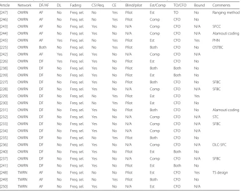
Literature review
The summary of the research
car-ried out to achieve timing and carrier synchronization in
single-carrier DF-OWRN is given in Table 11:
1. Estimation or compensation of frequency offset
alone is studied in [225–237].
2. Joint timing and carrier synchronization is studied in
[238–241].
Further details or differences are provided in the last
column of Table 11, which indicates if STBC or SFBC is
considered.
4.2.2
Decode-and-forward two-way relaying network
System model
Other than the IFFT/CP addition and CP
removal/FFT operations at the transmitter and receiver
side at each node, respectively, the system model for
DF-TWRN for multi-carrier systems is similar to that for
single-carrier systems presented in Section 4.1.2.
Synchronization challenge
The received signal at each
relay during the first communication phase is a
func-tion of two TOs and two CFOs, which need to be jointly
estimated and compensated. Thus, the synchronization
challenge is similar to that described for the second
com-munication phase of DF-OWRN with two TOs and two
CFOs. Moreover, the synchronization challenge during
the second communication phase of DF-TWRN is also
similar to the one described for the second
communica-tion phase of DF-OWRN in Seccommunica-tion 4.2.1.
Literature review
To the best of our knowledge, no
paper in the last 5 years falls into this category, since the
research in the synchronization of multi-carrier TWRN
has considered AF relaying.
4.2.3
Amplify-and-forward one-way relaying network
System model
The system model for AF-OWRN for
multi-carrier systems is similar to the one for
single-carrier systems presented in Section 4.1.3. However, being
an OFDM system, there are IFFT/CP addition and CP
removal/FFT operations at the source transmitter and
the destination receiver, respectively. Note that unlike
DF-OWRN for multicarrier systems, the FFT and IFFT
operations are not usually conducted at the receiver and
transmitter of the relays, respectively.
Table 11
Summary of synchronization research in multi-carrier cooperative communication systems
Article Network DF/AF DL Fading CSI Req. CE Blind/pilot Est/Comp TO/CFO Bound Comments
[247] OWRN AF No Freq. sel. No Yes Pilot Est TO No Ranging method
[246] OWRN AF No Freq. sel. No Yes Pilot Comp CFO No
[243] OWRN AF No Freq. sel. Yes No N/A Comp CFO N/A SFCC
[244] OWRN AF No Freq. sel. Yes No N/A Comp CFO N/A Alamouti coding
[245] OWRN AF Yes Freq. sel. No Yes Pilot Est CFO Yes PHN
[225] OWRN Both No Freq. sel. No Yes Pilot Both CFO No OSTBC
[242] OWRN AF Yes Freq. sel. Yes No N/A Comp CFO N/A
[226] OWRN DF Yes Freq. sel. Yes No Pilot Est CFO No
[238] OWRN DF No Freq. sel. Yes No Pilot Both Both No
[239] OWRN DF No Freq. sel. Yes No Pilot Est Both No
[227] OWRN DF No Freq. sel. Yes No Pilot Both CFO No SFBC
[228] OWRN DF No Freq. sel. Yes No N/A Comp CFO N/A SFBC
[229] OWRN DF No Freq. sel. No Yes Pilot Est CFO Yes
[230] OWRN DF No Freq. sel. No Yes Pilot Est CFO No
[231] OWRN DF No Freq. sel. Yes No Pilot Both CFO No Alamouti coding
[232] OWRN DF No Freq. sel. Yes No N/A Comp CFO N/A STC
[233] OWRN DF No Freq. sel. Yes No N/A Comp CFO N/A SFBC
[234] OWRN DF No Freq. sel. Yes No N/A Comp CFO N/A
[235] OWRN DF No Freq. sel. No Yes Pilot Both CFO No
[236] OWRN DF No Freq. sel. Yes No N/A Comp CFO N/A DLC-SFC
[240] OWRN DF No Freq. sel. Yes No Pilot Est Both No
[237] OWRN DF No Freq. sel. Yes No N/A Comp CFO N/A SFBC
[241] OWRN DF No Freq. sel. Yes No Pilot Est Both No
[248] TWRN AF No Freq. sel. No No Pilot Est CFO Yes TS design
[249] TWRN AF No Freq. sel. No Yes Pilot Both CFO No
[250] TWRN AF No Freq. sel. Yes No N/A Est CFO N/A
Literature review
The summary of the research
car-ried out to achieve timing and carrier synchronization in
single-carrier AF-OWRN is given in Table 11. The
estima-tion or compensaestima-tion of timing offset alone and frequency
offset alone is studied in [225, 242–246] and [247],
respec-tively. Further details or differences are provided in the
last column of Table 11, which indicates if any additional
parameter, e.g., phase noise (PHN) estimation, is
consid-ered or if STBC or any other type of space coding is
considered.
4.2.4
Amplify-and-forward two-way relaying network
System model
Apart from the IFFT/CP addition and CP
removal/FFT operations at the transmitter and receiver,
respectively, the system model for AF-TWRN for
multi-carrier systems is similar to the one for single-multi-carrier
systems presented in Section 4.1.4. Note that unlike
DF-TWRN for multicarrier systems, the FFT and IFFT
oper-ations are not usually conducted at the receiver and
transmitter of the relays, respectively.
Synchronization challenge
The required parameters to
be estimated and compensated to achieve
synchroniza-tion in multi-carrier AF-TWRN are similar to the one
described in the synchronization challenge of
single-carrier AF-TWRN in Section 4.1.4. The difference is to
mitigate the effect of ISI and ICI in OFDM systems.
Literature review
The summary of the research
car-ried out to achieve timing and carrier synchronization in
single-carrier AF-OWRN is given in Table 11. The
estima-tion or compensaestima-tion of frequency offset alone is studied
in [248–250]. The categorized papers differ in the sense
that training sequence design is proposed in [248], joint
CFO estimation and compensation with channel
estima-tion is studied in [249], and CFO estimaestima-tion alone is
proposed in [250].
4.2.5
Summary
and MCFOs has been considered in very few works, e.g.,
[228]. Future research investigations may help to achieve
efficient algorithms. In addition, solution to the
particu-lar problem in TWRNs and the derivation of CRLBs are
open research areas in this field. Moreover, most of the
solutions are pilot based. Hence, it is a challenging open
problem to design semiblind and blind estimators.
5
Multiuser/multicell interference networks
5.1
SC-FDMA uplink communication systems
Single-carrier frequency division multiple access
(SC-FDMA) is an extension of SC-FDE to accommodate
mul-tiple users. In SC-FDMA uplink communication systems,
multiple users communicate with a single receiver and
the effect of channel distortion is equalized in frequency
domain at the receiver. Like the SC-FDE receiver, FFT
and IFFT modules are present in the SC-FDMA receiver.
However, the SC-FDMA transmitter also incorporates
FFT and IFFT modules. Disjoint sets of
M
subcarriers
are assigned to each of the
K
users, and data symbols
from each user are modulated over a unique set of
sub-carriers through an
M
-point FFT operation. Next,
KM
-point IFFT is applied to transform the signal to time
domain, such that the output of FFT is applied to the
user-specified
M
inputs of IFFT block and 0 is applied
to the remaining
(
K
−
1
)
M
inputs of IFFT block. Next,
cyclic prefix is appended at the start of the
transmis-sion block to mitigate the multipath channel effect. At
the receiver side, following
KM
-point FFT and frequency
domain equalization,
K
of
M
-point IFFT operations are
applied to decode the information from the
K
users.
SC-FDMA can also be interpreted as a linearly precoded
OFDMA scheme, in the sense that it has an additional
FFT processing step preceding the conventional OFDMA
processing.
Due to the presence of an independent oscillator at each
transmitting user and due to different propagation delays
between each user and the receiver, the received signal in
the SC-FDMA uplink communication system suffers from
multiple CFOs and multiple TOs. The combined effect
of TOs and CFOs results in both ISI and loss of
orthog-onality among subcarriers, which, in turn, generates ICI
and multiple access interference (MAI) at the receiver.
Thus, in order to decode information from each user, a
receiver has to estimate multiple TOs and multiple CFOs
to compensate the effect of ICI, ISI, and MAI. In uplink
communication systems, there is another synchronization
challenge that the correction of one user’s frequency and
timing at the receiver can misalign those of the other
users [251].
It must be noted that LTE systems [252] use
SC-FDMA for c