18th International Conference on Structural Mechanics in Reactor Technology (SMiRT 18) Beijing, China, August 7-12, 2005 SMiRT18-S04-7
TURBO-MACHINE DEPLOYMENT OF HTR-10GT
Shutang ZHU
Institute of Nuclear and New Energy
Technology, Tsinghua University
Beijing 100084, P R China
Phone: +86-10-62783555
Fax: +86-10-62771150
E-mail: [email protected]
Jie WANG
Institute of Nuclear and New Energy
Technology, Tsinghua University
Beijing 100084, P R China
Phone: +86-10-62794678
Fax: +86-10-62771150
E-mail:
[email protected]
Zhengming ZHANG
Institute of Nuclear and New Energy
Technology, Tsinghua University
Beijing 100084, P R China
Phone: +86-10-62784809
Fax: +86-10-62771150
E-mail:
[email protected]
Suyuan YU
Institute of Nuclear and New Energy
Technology, Tsinghua University
Beijing 100084, P R China
Phone: +86-10-62796434
Fax: +86-10-62771150
E-mail: [email protected]
ABSTRACT
As a testing project of gas turbine modular High Temperature Gas-cooled Reactor (HTGR), HTR-10GT has been studied and developed by Institute of Nuclear and New Energy Technology (INET) of Tsinghua University after the success of HTR-10 with steam turbine cycle. The main purposes of this project are to demonstrate the gas turbine modular HTGR, to optimize the deployment of Power Conversion Unit (PCU) and to verify the techniques of turbo-machine, operating modes and controlling measures. HTR-10GT is concentrated on the PCU design and the turbo-machine deployment. Possible turbo-machine deployments have been investigated and two of them are introduced in this paper. The preliminary design for the turbo-machine of HTR-10GT is single-shaft of vertical layout, arranged by the side of the reactor and the turbo-compressor rotary speed was selected to be 250 s-1 (15000r/min) by considering the efficiency of turbo-compressor blade systems, the strength conditions and the mass and size characteristics of the turbo-compressor. The rotor system will be supported by electromagnetic bearings (EMBs) to curb the possible pollutions of the primary loop. Of all the components in this design, the high speed turbo-generator seems to be a world-wide technical nut. As an alternative design, a gearbox complex is used to reduce the rotary speed from the turbo-compressor 250 s-1 to 50 s-1 so that the ordinary generator can be used
Keywords: Brayton cycle, Gas turbine cycle, Gas turbine HTGR, HTR-10GT, Power Conversion Unit
1. INTRODUCTION
criticality by the end of 2000 (Wu et al. 2002, Xu and Zuo 2002) while the plant with steam turbine loop reached its full power at the beginning of 2003. Thereafter, a lot of running tests and inherent safety experiments has been performed on it. All the tests and experiments verified the passive safety (inherent safety) concept of HTGR.
International interest in modular HTGR technology has been increasing in recent years due to a growing recognition of high efficiency potential of HTGR designs and providing a source of high temperature process heat. With its inherent safety and high temperature capability, HTGR has been taken as one main type of the Generation-IV Nuclear Power Plant (NPP) types (Magwood IV, 2000; USA Doe, 2001) and will become an important option for nuclear energy in the world. Considerable cost savings could result from application of a closed Brayton cycle using advances in technology for open cycle gas turbines, compact heat exchangers, manufacturing and electronics and the resulting gas turbine modular HTGR could reach a relatively higher thermal efficiency, up to 50%. These possibilities have brought about an increasing interest by international research organizations and plant developers. A series national / international projects based on such technology are being carried out in dozen of countries including China, Netherlands, Russia, South Africa, UK, US, and also Japan.
The GT-MHR facility involves participants from France, Japan, the Russian Federation and the United States of America and is intended to be constructed in Russia (Simon and Shenoy 1997). It is designed for utilization of nuclear energy through a gas-turbine HTGR with electricity efficiency of about 50%. As a part of the conceptual design, a reactor module with a power conversion system was being designed (Kiryushin et al., 1997). Dynamic models of a nuclear gas turbine power plant are presented: both the high temperature nuclear reactor and its energy conversion system based on a direct Brayton cycle have been modeled (Verkerk and Kikstra, 2003). Optimization studies for the GT-MHR power conversion unit have been conducted to determine design layout and operating conditions. A single shaft turbo-machine was selected to provide protection against over-speed on a loss of electrical load.
The Pebble Bed Modular Reactor (PBMR) was first identified by Eskom in South Africa and has been under development since 1994. This project involves partners and contractors from France, Germany, Netherlands, the Russian Federation, South Africa, the UK and the USA. Its reactor development follows the HTR-MODULE pebble bed. The conceptual design has moved from a copy of the HTR-Module developed in Germany to a direct gas cycle design utilizing the Brayton cycle. This design change allows a thermal reactor power of 400 MW and keeps the operating fuel temperature below 1130°C for low fission product contamination of the turbines (Koster et al. 2003). ESKOM and its partners are currently in the process of performing the final evaluation for the introduction of this advanced nuclear power reactor coupled to a closed cycle gas turbine as additional generation capacity on their electric grid and for commercialization in the international market place.
A number of HTGR gas turbine plant designs have been under development by Japan Atomic Energy Research Institute (JAERI) within the framework of the Japanese HTGR-GT feasibility study program. The 300 MW(t) plant of pebble bed annular reactor provides a core outlet temperature of 900°C to the turbine of a single shaft machine with the capability to provide 283 tons / hour of desalinated water through an additional heat exchanger between the recuperator and pre-cooler. The net thermal efficiency for this plant is anticipated at 48.2% (Muto 1999). Another is the GTHTR 300 Plant, which incorporates a 600 MW(t) hexagonal fuel block core. The power conversion system includes a vertical heat exchanger vessel and a horizontal turbo-machine vessel to allow for bearing support and stable rotor operation. The overall net plant efficiency for this simplified unit is 45.4% (Yan et al. 1999).
Based on the successful operation of HTR-10, INET set up the HTR-10GT project coupling HTR-10 with gas turbine cycle (Zhang and Yu, 2002). This project uses a direct gas turbine cycle to convert the nuclear energy into electricity. The PCU includes the turbo-machine consisting of a turbine, two compressors and a generator (Wang et al., 2004), all of which will be installed in the PCU pressure vessel. At the full power condition, the temperatures at inlet and outlet are designed to be 330°C and 750°C respectively while the core pressure is designed to be 1.56 MPa with a helium flow rate of 4.56 kg/s. The design of turbo-compressor is based on above described conditions. The compromise of material strength and the turbo-compressor features gives a rotary speed of 250 s-1 (15,000 r/min). All other features of the PCU components are based on these basic parameters.
the choice of high-speed turbo-compressor with ordinary generator are compared. Section 5 gives brief conclusions.
2. THERMAL CIRCULATION FOR HTR-10GT
2.1 Reviews on HTR-10
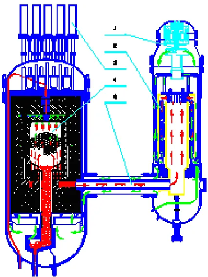
The steam turbine plant of HTR-10 has two circulation systems, the primary loop and the second loop incorporated by the steam generator. The primary loop consists of the reactor core, the hot gas duct, the steam generator and the helium blower (Wu et al., 2002). The second loop consists of the steam generation, the steam turbine, the cooling tower and the circulation pump. The reactor core was designed to be installed in the reactor pressure vessel while the steam generator and the helium blower with its driving motor were installed in a separated steam generator pressure vessel. These two pressure vessels are arranged side by side and are connected by the horizontal coaxial hot-gas duct, as shown in Fig. 1.
1: helium circulator; 2: steam generator; 3: control rod; 4: reactor core; 5: hot gas duct
Fig. 1 The side-by-side arrangement of pressure vessels for HTR-10
For the primary loop of HTR-10, the pressure is design to be 3.0MPa while the temperatures at the inlet and outlet of the reactor core are 250 and 700. The loop blower can provide a pressure head of 27.2 Pa at a mass flow rate of 4.32 kg/s. For the second loop, the steam generator provides the steam turbine with water steam temperature of 435 and inlet pressure of 3.45 MPa at a mass flowrate of 3.49 kg/s. With respect to thermodynamic circulations, the HTR-10 plant is similar to a PWR plant (see Fig. 2) with the difference of working medium in the primary loop. The utilization of Rankine Cycle also determines that the final efficiency cannot reach a high level (lower than 40%)
2.2 Thermodynamic design of HTR-10GT
The HTR-10GT project is developed based on the reactor of HTR-10. Its thermal circulation is a closed recuperated and inter-cooled Brayton Cycle consisting of the reactor core, a helium turbine, a recuperator, a pre-cooler, a LPC, an inter-cooler and a HPC, as shown in Fig. 3.
Fig. 3 Schematic diagram of gas turbine HTGR
The nuclear energy is first converted to thermal energy carried by helium in the reactor. The heated helium from the reactor comes to the turbine inlet, expands to do work in turbine and passes through the recuperator - lower pressure (LP) side where it transfers heat to its high pressure (HP) side. Then helium from the recuperator comes to the pre-cooler where it is cooled. After cooling, helium comes to the LPC inlet, where it is subject to compression and comes to the inter-cooler for cooling to increase HPC efficiency, then after cooling it flows to the inlet of HPC. In the HPC helium is subject to subsequent compression, and then it passes through the recuperator - HP side where it is pre-heated and comes to the reactor core. Helium passes the reactor core, is heated again thus closing circulation cycle in the circuit. Fig. 4 shows the helium circulation flow path of HTR-10GT.
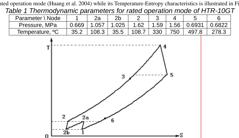
The thermodynamic parameters of HTR-10GT at each node illustrated in Fig. 3 are described in Table 1 for its rated operation mode (Huang et al. 2004) while its Temperature-Entropy characteristics is illustrated in Fig. 5.
Table 1 Thermodynamic parameters for rated operation mode of HTR-10GT
Parameter \ Node 1 2a 2b 2 3 4 5 6Pressure, MPa 0.669 1.057 1.025 1.62 1.59 1.56 0.6931 0.6822 Temperature, ºC 35.2 108.3 35.5 108.7 330 750 497.8 278.3
Fig. 5 Relationship between temperature and entropy for HTR-10GT
3. TURBO-COMPRESSOR DESIGN
3.1 Determination of the rotary speed
The turbo-compressor design mainly depends on its rotary speed, which is determined so that rather high efficiency of blade systems for compressors and turbine can be achieved, generator rotor strength be met and acceptable mass and size characteristics of the turbo-compressor itself be obtained. As a result of the analysis the rotary speed was selected to be 250 s-1. At such a rotary speed the main geometrical correlations are achieved (relative radial gaps, sleeve ratios) which ensure the possibility to create blade systems with rather high efficiency. Furthermore, acceptable mass and size characteristics of the turbo-compressor are achieved and strength conditions for the generator rotor in the turbo-machine are met.
3.2 Turbo-compressor structure
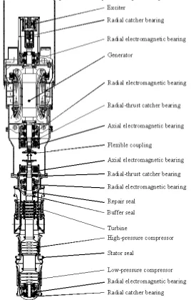
The turbo-compressor, consisting of LPC, HPC and turbine in axial upwards direction, is arranged in a single vertical structure which represents a separate unit. The turbo-compressor is mounted on the support plate of PCU in-vessel metal works. Physical boundaries of the turbo-compressor are interface joints between its stator and PCU in-vessel metal works and generator frame, inlet nozzle to the LPC and upper end of its shaft.
The turbo-compressor rotor rotates in two radial and one axial EMBs. There is a buffer gas seal located above the turbine. Above the buffer seal there is a repair seal installed. External surface of the turbo-compressor stator is provided with stator seals in joints where cavities with different pressure are located.
3.3 Functions of turbo-compressor components
3.4 Description of turbo-compressor design
3.4.1 Compressors design
To demonstrate the gas turbine HTGR for commercial purpose, axial type LPC and HPC are adopted though the flow rate is too small to achieve high efficiency of the blade system. For both the LPC and HPC the compression ratio is set to be 1.58 with an adiabatic efficiency of 84.5% for the blade system at the expense of 1.7 88 MW exhausted by LPC and 1.797 MW by HPC. The stator casing is designed in the form of a hollow cylinder with longitudinal joint in rotor axis plane. The rotor represents a welded structure of drum-disk type where disks are fitted with drum sectors and consecutively connected with each other by electron-beam welding. Working blades are attached by means of annular groove made in the form of trapezoidal slot (“dovetail”) in rotor drum part. Straightening apparatus are made as cantilever and consist of outer ring and straightening blades. Blades of the straightening apparatus are fixed in the outer ring where threaded holes are provided to fix the straightening apparatus to the stator casing. Between internal surface of the straightening apparatus and external surface of the rotor in each stage there is a gap seal to reduce helium leaks.
3.4.2 Turbine design
The turbine is expected to do 5.861 MW work with an expansion ratio of 2.253 and adiabatic efficiency of 86.5% at a flow rate of 4.64 kg/s. The turbine stator represents a single-piece hollow cylindrical structure and includes six stages of nozzle apparatus, six inserts made of segments and the stator casing. Nozzle apparatus are fixed in the stator. To reduce leaks between sections of nozzle blades plates are installed in recesses of external shelves. Rings with soldered honeycomb seals are attached to the internal diameter of the nozzle apparatus. The turbine rotor consists of six impellers, each of which includes a disk and working blades which are fixed in the disk. Honeycomb seals in inserts made of segments incorporated in the turbine stator casing and in rings of nozzle apparatus are provided to avoid damage.
4. DEPLOYMENT OF THE TURBO-MACHINE
4.1 The purpose of turbo-machine for HTR-10GT
The turbo-compressor together with the generator form the turbo-machine of HTR-10GT, which is used to convert thermal energy into electricity and to provide primary coolant circulation, thus can be called the heart of HTR-10GT. The turbo-machine will provide a net electricity load equal to the result that the work done by turbine subtracts the work exhausted by LPC and HPC, say 2.276 MW (=5.861 - 1.788 -1.797). Thus the electricity efficiency of HTR-10GT testing plant is less than 22.76%. Factors restricting the possibility to achieve analytical efficiency values typical for the full-scale commercial plants are as follows:
- Relatively small power of the turbo-compressor. Efficiency is reduced due to relative large values of leaks between the stators and blades system of turbine and compressors.
- Thermal parameters restricted by the existing reactor pressure vessel. The temperature and pressure are not optimal for commercial designs.
- Restricted recuperator dimensions with recuperation factor in the cycle.
Despite the fact that HTR-10GT gas-turbine cycle parameters differ from those of the prototype commercial ones, the implementation of turbo-machine for HTR–10GT will make it possible to carry out in-depth study of the technology of its commercial application.
- To acquire practical experience of creation, mounting, startup and adjustment activities, maintenance, repair;
- To confirm the adopted principle decisions (schematic, structural and others).
- To develop operation modes of reactor operation and gas-turbine facility, turbo-machine control and protection methods during investigations and pilot operation.
4.2 The preliminary turbo-machine design
4.2.1 Arrangement
modes: motoring mode and generating mode. At the HTR-10GT plant starts, shutdowns or cool-downs, it operates in a motoring mode. For electricity generation, it operates in generating mode.
Fig. 6 Turbo-machine deployment in the preliminary design
The steam generator pressure vessel for HTR-10 will be replaced by the PCU pressure vessel for HTR-10GT. The turbo-machine is located in the central part of PCU vessel and mounted on the support plate of PCU in-vessel metal works, as illustrated in Fig 7.
4.3.2 Technical difficulties
For the single-shaft design of turbo-machine, the generator rotor runs at the speed of 250 s-1 with a corresponding frequency converter connecting to the electricity grid. For such a high-speed generator, there exist a lot of technical difficulties to be solved. The rotor should be made of solid forging piece of high strength alloyed steel whose mechanical properties were improved by special thermal treatment. Rotor winding overhang should be secured with the help of bandage units, which represent a system of rings. Load-carrying ring should be made of strengthened material. As well as we known, none of generator manufacturers has the experience on the design and fabrication of such a generator.
The rotor dynamics of such a complex structure is the primary difficulty to be solved, especially its coupling with the turbo-compressor rotor through the flexible coupling.
The cooling of the rotor and winding overhang is another technical difficulty. Because of the high-speed, the design of ventilation system and the calculation of aerodynamic resistance will be very complicated. Specific mathematical simulation of the generator ventilation system should be made.
The frequency converter is also a technical difficulty.
Further investigations shows that the single-shaft design of turbo-machine will bring a serial of engineering risks to the HTR-10GT project.
Fig. 7 Layout of the turbo-machine in PCU vessel of HTR-10GT
4.3 The alternative turbo-machine design
4.3.1 Redesign the turbo-machine
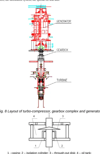
None of the purpose of turbo-machine for HTR-10GT is to investigate the high-speed generator or the frequency converter. To lower the risk of the HTR-10GT project, the high-speed generator together with frequency converter in the preliminary design of turbo-machine should be given up. Special speed-reduction equipment – a vertical gearbox complex can be adopted to reduce the turbo-compressor’s rotary speed from 250 s-1 to 50 s-1 so that the ordinary generator with a rotary speed concord the electricity grid can be used. Thus, the turbo-machine for energy conversion consists of the turbo-compressor running at a rotary speed of 250 s-1, the gearbox complex changing the rotary speed form 250 s-1 to 50 s-1., the vertical generator running at a speed of the 50 s-1, a flexible coupling connecting the turbo-compressor rotor and the input shaft of gearbox complex and another flexible coupling connecting the output shaft of gearbox complex and the generator rotor. The arrangement of the alternative turbo-machine is illustrated in Fig. 8.
4.3.2 Technical difficulties and solutions
contain the oil. The details of the oil seal unit can be referred to Fig. 9. Thus, the gearbox complex consists of the gearbox itself, the lubrication system, the special oil seal unit.
Fig. 8 Layout of turbo-compressor, gearbox complex and generator
1 - casing; 2 – isolation cylinder; 3 – through-out disk; 4 – oil tank;
Fig. 9 Schematic diagram of the special designed oil seal unit
4.3.3 Deployment of the alternative turbo-machine
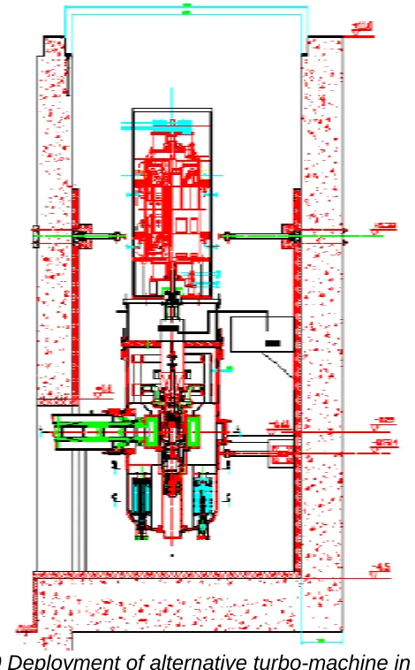
In the preliminary PCU design of HTR-10GT, the turbo-machine was designed as a single-shaft deployed in the center of the PCU vessel. For such an arrangement, flow channels connecting functional components are very complicated. This causes a relatively high pressure loss totaled 11.62%, and lowers the electricity efficiency to be less than 23%.
Fig. 10 Deployment of alternative turbo-machine in PCU
In the alternative turbo-machine design, we plan to re-deploy all the components in the PCU vessel. First of all, the turbo-compressor will be shifted to a lower location so that its inlet duct is on the same centerline as the hot-gas-conduct to reduce the pressure loss and to ensure the potential to do work. The units of rercuperator will be arranged around the turbine and closed to the turbine outlet to shorten the connecting channels from turbine outlet to recuperator and from recuperator to HPC outlet. Same heat exchangers are designed for both the pre-cooler and the inter-cooler. All the 8 heat exchanger units (5 units are for pre-cooler and 3 units for inter-cooler) will be arranged in the lower annual space around the turbo-compressor to shorten the connecting channels. The PCU vessel will be separated into the lower cavity, which contains all the components of the primary loop, and the upper cavity, which contains the gearbox, generator and other auxiliary equipment. These two cavities will be isolated by the buffer gas seal at the upper shaft of the turbo-compressor. The arrangement of the alternative turbo-machine in PCU vessels is illustrated in Fig. 10.
5. CONCLUSIONS
HTR-10GT testing plant is less than 22.76%. The turbo-machine within the PCU for HTR–10GT will allow investigations related to incorporation of commercial gas turbine modular HTGR plant.
In the preliminary design, the turbo-machine represents a vertical machine including the generator, the turbo-compressor and the flexible coupling, which connects turbo-compressor rotor and generator rotor. The turbo-machine is located in the central part of PCU vessel and mounted on the support plate of PCU in-vessel metal works while its rotor is suspended by EMBs. For such a design, several technical difficulties including the high-speed generator, the corresponding frequency converter and also the arrangement of heat exchangers.
For lowering technical risk, an alternative turbo-machine design is considered, in which a special designed gearbox complex is used to reduce the rotary speed from 250 s-1 to 50 s-1 so that an ordinary generator with a frequency of the electricity grid can be adopted. New technical problems brought in the alternative design were considered and solutions were investigated. All the heat exchangers were re-arranged close to the functional components to reduce the pressure loss in connecting channels.
ACKNOWLEDGMENTS
This study is jointly sponsored by the National Natural Science Foundation of China under Grant No. 90410001 and by the State ‘863’ High-Tech Planning Project HTR-10GT. The authors wish to express their thanks to the OKBM specialists for their significant contributions to the preliminary PCU design of HTR-10GT project during the cooperation.
REFERENCES
[1] Brey, H.L., 2000. Development History Of The Gas Turbine Modular High Temperature Reactor. IAEA-TECDOC-1238.
[2] Huang, Z., Wang, J., Li, J., 2004. Study on the thermodynamic cycle of HTR-10GT. Proc. 2nd Inter. Topical Meeting on HTR Tech. - #D01, Beijing, China, 22-24 September 2004.
[3] Kiryushin, A.I., Kodochigov, N.G., Kouzavkov, N.G., Ponomarev-Stepnoi, N.N., Gloushkov, E.S., Grebennik, V.N., 1997. Project of the GT-MHR high-temperature helium reactor with gas turbine. Nucl. Eng. Des. 173, 119-129.
[4] Koster, A., Matzner, H.D., Nicholsi, D.R., 2003. PBMR design for the future. Nucl. Eng. Des. 222, 231-245.
[5] Lohnert, G.H., Nabielek, H., Schenk, W., 1988. The fuel element of the HTR-Module, a prerequisite of an inherently safe reactor. Proc. 10th Inter. Conf. HTGR’s, San Diego, USA, Paper II.24.
[6] Magwood IV, W., 2000. Roadmap to the next generation of nuclear power systems: A vision for a powerful future. Nuclear News, November 2000.
[7] Muto, Y., 1999. Present activity of the design and experimental works for HTGR-GT system in JAERI. EPRI Helium Gas Turbine Reactor Workshop, Palo Alto, California, December 7-8, 1999.
[8] Simon, W.A., Shenoy, A.S., 1997. International cooperation in developing the GT-MHR, evolution and program Status. Proc. IAEA Tech. Committee Meeting on HTGR App. and Future Prospects, ECN-R-98-004, Petten, the Netherlands, 10-12 November 1997.
[9] US DOE, 2001. “Generation IV”, website on the Internet at http://gen-iv.ne.doe.gov.
[10] Verkerk, E.C., Kikstra, J.F., 2003. Comparison of two models for a high temperature reactor coupled to a gas turbine. Nucl. Eng. Des. 220, 51-65.
[11] Wang, J., Huang, Z., Zhu, S., Yu, S., 2004. Design Features of Gas Turbine Power Conversion System for HTR-10GT. Proc. 2nd Inter. Topical Meeting on HTR Tech. - #D05, Bejing, China, 22-24 September 2004.
[12] Weisbrodt, I.A., 2003. Inherently Safety Design Features of the HTR-Module, IAEA-CN-48/125. HTGR, The Modular High-temperature Gas-cooled Reactor (MHTGR) in the U.S., Doe-HTGR-87-088. [13] Wu, Z., Lin, D., Zhong, D., 2002. The design features of the HTR-10. Nucl. Eng. Des. 218, 25-32. [14] Xu, Y., Zuo, K., 2002. Overview of the 10MW high temperature gas-cooled reactor test module
project. Nucl. Eng. Des. 218. 13-23.
[15] Yan, X., Shiozawa, S., Kunitomi, K., Muto, Y., Miyamoto, Y., 1999. Design of gas turbine High Temperature Reactor-GTHTR 300. EPRI helium gas turbine reactor Workshop, Palo Alto, California, December 7-8, 1999