ABSTRACT
LIU, YAO. Wireless Physical Layer Security. (Under the direction of Peng Ning.)
Wireless communication is ubiquitous today. Various wireless applications like WiFi, bluetooth, and cellular networks have been widely used in people’s daily life. How to protect the physical layer of wireless communication is crucial for applications where reliable information exchange is required. On the other hand, characteristics of wireless physical layer create new opportunities for us to come up with novel and efficient approaches that can guarantee the security of wireless physical layer. This dis-sertation includes four work toward the protection of wireless physical layer. The first and second work propose solutions to combat jamming attacks, which are well known threats to wireless communica-tions. The third work utilizes physical layer characteristics to authenticate wireless signal for cognitive radio networks (CRNs), and the lats work identifies and addresses vulnerabilities existing in the link signature authentication techniques.
The first work, targets at a well known threat to wireless communications, i.e., jamming attacks. Jamming resistance is crucial for applications where reliable wireless communication is required. Spread spectrum techniques such as Frequency Hopping Spread Spectrum (FHSS) and Direct Sequence Spread Spectrum (DSSS) have been used as countermeasures against jamming attacks. Traditional anti-jamming techniques require that senders and receivers share a secret key in order to communicate with each other. However, such a requirement prevents these techniques from being effective for anti-jamming broadcast communication, where a jammer may learn the shared key from a compromised or malicious receiver and disrupt the reception at normal receivers.
To address this problem, we propose a Randomized Differential DSSS (RD-DSSS) scheme to achieve anti-jamming broadcast communication without shared keys. RD-DSSS encodes each bit of data using the correlation of unpredictable spreading codes. Specifically, bit “0” is encoded using two different spreading codes, which have low correlation with each other, while bit “1” is encoded using two identical spreading codes, which have high correlation. To defeat reactive jamming attacks, RD-DSSS uses multiple spreading code sequences to spread each message and rearranges the spread output before transmitting it. Theoretical analysis and simulation results show that RD-DSSS can effectively defeat jamming attacks for anti-jamming broadcast communication without shared keys.
communication in the presence of a broadband and high power reactive jammer. BitTrickle transmits messages by taking advantage of the subtle opportunity that arises from the reaction time of a reactive jammer. Unlike FHSS and DSSS, BitTrickle does not assume a reactive jammer with limited spectrum coverage and transmit power, and thus can be used in scenarios where traditional approaches fail. We develop a prototype of BitTrickle using GNURadio to evaluate the performance of BitTrickle. Our re-sults show that when a reactive jammer is turned on, BitTrickle still maintains wireless communication, whereas other schemes such as 802.11 DSSS fails to deliver packets.
The third work targets at wireless signal authentication in cognitive radio networks. Cognitive radio networks have been proposed to increase the efficiency of channel utilization and address the increasing demand for wireless bandwidth; they enable the sharing of channels among secondary (unlicensed) and primary (licensed) users on a non-interference basis. A secondary user in a CRN should constantly monitor for the presence of a primary user’s signal to avoid interfering with the primary user. However, to gain unfair share of radio channels, an attacker (e.g., a selfish secondary user) may mimic a primary user’s signal to evict other secondary users. Therefore, a secure primary user detection method that can distinguish a primary user’s signal from an attacker’s signal is needed. A unique challenge in addressing this problem is that Federal Communications Commission (FCC) prohibits any modification to primary users. Consequently, existing cryptographic techniques cannot be used directly.
In this work, we develop a novel approach for authenticating primary users’ signals in CRNs, which conforms to FCC’s requirement. The proposed approach integrates cryptographic signatures and wire-less link signatures (derived from physical radio channel characteristics) to enable primary user detec-tion in the presence of attackers. Essential to the proposed approach is a helper node placed physically close to a primary user. The helper node serves as a “bridge” to enable a secondary user to verify cryp-tographic signatures carried by the helper node’s signals and then obtain the helper node’s authentic link signatures to verify the primary user’s signals. A key contribution is a novel physical layer au-thentication technique that enables the helper node to authenticate signals from its associated primary user. Unlike previous techniques for link signatures, the proposed approach explores the geographical proximity of the helper node to the primary user, and thus does not require any training process.
c
Copyright 2012 by Yao Liu
Wireless Physical Layer Security
by Yao Liu
A dissertation submitted to the Graduate Faculty of North Carolina State University
in partial fulfillment of the requirements for the Degree of
Doctor of Philosophy
Computer Science
Raleigh, North Carolina 2012
APPROVED BY:
Douglas S. Reeves Huaiyu Dai
Xuxian Jiang Peng Ning
DEDICATION
BIOGRAPHY
ACKNOWLEDGEMENTS
TABLE OF CONTENTS
List of Tables . . . . viii
List of Figures . . . . ix
Chapter 1 Introduction . . . 1
1.1 Randomized Differential Direct Sequence Spread Spectrum . . . 1
1.2 BitTrickle: Wireless Communication under Broadband and High Power Reactive Jamming 3 1.3 Authenticating Primary Users’ Signals in CRNs . . . 5
1.4 Mimicry Attacks against Wireless Link Signature and Defense using Time-Synched Link Signature . . . 7
1.5 Summary of Contributions . . . 8
Chapter 2 Randomized Differential Direct Sequence Spread Spectrum . . . . 10
2.1 Background on DSSS . . . 10
2.2 System and Threat Models . . . 12
2.3 Randomized Differential DSSS . . . 12
2.3.1 Basic Scheme . . . 12
2.3.2 Enhanced Scheme: Defending against Reactive Jamming . . . 15
2.4 Performance Overheads . . . 17
2.5 Security Analysis and Simulation . . . 18
2.5.1 Classification of Jamming Attacks . . . 18
2.5.2 Intelligent Jamming Attacks . . . 19
Chapter 3 BitTrickle: Combating Broadband and High Power Reactive Jamming . . . . 27
3.1 Assumptions and Threat Model . . . 27
3.2 Overview of BitTrickle . . . 27
3.2.1 Transmission at the Sender . . . 28
3.2.2 Reception at the Receiver . . . 29
3.2.3 Technical Challenges . . . 30
3.3 Jamming Detector-Identifying Jammed Bits . . . 31
3.3.1 Preliminaries on Modulation . . . 31
3.3.2 Experimental Observation . . . 32
3.3.3 Detection Method . . . 33
3.3.4 False Alarms and False Negatives . . . 34
3.3.5 Determining the Threshold . . . 36
3.4 BitTrickle Encoding/Decoding . . . 37
3.4.1 Basic Idea . . . 37
3.4.2 Encoding at Sender . . . 39
3.4.3 Decoding at Receiver . . . 40
3.5 Implementation and Evaluation Results . . . 45
3.5.1 Component Evaluation . . . 48
Chapter 4 Authenticating Primary Users’ Signals in Cognitive Radio Networks . . . . . 54
4.1 Preliminaries . . . 54
4.2 Assumptions and Threat Model . . . 56
4.3 Overview . . . 57
4.3.1 Technical Challenges . . . 58
4.4 Authenticating Primary User’s Signal at the Helper Node . . . 58
4.4.1 Observation . . . 59
4.4.2 Authentication Method . . . 59
4.4.3 Theoretical Analysis . . . 63
4.5 Interaction between the Helper Node and Secondary Users . . . 69
4.5.1 Obtaining Training Link Signatures . . . 69
4.5.2 Verifying Link Signatures . . . 71
4.6 Experimental Evaluation . . . 72
4.6.1 Authentication at the Helper Node . . . 72
4.6.2 Authentication at Secondary Users . . . 75
4.7 Implementation . . . 78
Chapter 5 Mimicry Attacks against Wireless Link Signature and Defense Design . . . . 81
5.1 Preliminaries . . . 81
5.1.1 Multi-path Effect and Link Signature . . . 81
5.1.2 Link Signatures v.s. Cryptographic Signatures . . . 81
5.1.3 Estimating Channel Impulse Responses . . . 82
5.2 Mimicry Attack . . . 83
5.2.1 Learning Symbolsyt . . . 84
5.2.2 Manipulating Transmitted Symbols . . . 85
5.2.3 Initial Validation via CRAWDAD Data Set . . . 86
5.2.4 Extending Attack to Multiple Tone Probing Link Signature . . . 87
5.3 Time-synched Link Signature . . . 87
5.3.1 Assumptions and Threat Analysis . . . 87
5.3.2 Design Strategy . . . 88
5.3.3 Training Phase . . . 91
5.3.4 Operational Phase . . . 92
5.3.5 Security Analysis . . . 93
5.4 Experimental Evaluation . . . 93
5.4.1 Evaluation Methodology . . . 94
5.4.2 Evaluation Results . . . 94
Chapter 6 Related Work . . . . 101
6.1 Anti-jamming Defense Design . . . 101
6.2 Primary User Detection in Cogitative Radio Networks . . . 102
6.3 Wireless Transmitter Authentication . . . 103
Chapter 7 Future Work . . . 104
LIST OF TABLES
Table 2.1 computation time (milliseconds) . . . 18 Table 3.1 Technical details of the reactive jammer . . . 47 Table 4.1 Trade off betweenPF A andPF N . . . 75 Table 4.2 Trade off betweenPF AandPF N: the probabilityPD of false negative decreases
LIST OF FIGURES
Figure 1.1 Reactive jamming: The first∆tRbits of the sender’s packet are jamming-free, where∆tandRare channel sensing delay of the jammer and the transmission
bit rate of the sender, respectively. . . 4
Figure 2.1 A simple communication framework of DSSS . . . 10
Figure 2.2 An example of the basic RD-DSSS scheme. . . 13
Figure 2.3 Theoretical probability that an attacker jams communication fork= 5 . . . 21
Figure 2.4 Simulated and theoretical probabilities that an attacker jams communication whenM = 60 . . . 21
Figure 2.5 Simulated and theoretical probabilities that an attacker jams communication whenn= 120 . . . 21
Figure 2.6 E(f·h)andE(f·g)(k= 5,n= 30) . . . 23
Figure 2.7 E(f·h)andE(f·g)(k= 5,l= 300) . . . 23
Figure 2.8 Simulated and theoreticalE(f·h)forn= 30,n= 50, andn= 80 . . . 24
Figure 2.9 E(f·h)andE(f·g)(k= 5,n= 30) . . . 24
Figure 2.10 Simulated and theoreticalE(f·h)fork= 1andk= 5(l= 300) . . . 25
Figure 3.1 Reactive jammer starts jamming once detecting sender’s transmission. . . 28
Figure 3.2 Transmission at the sender . . . 29
Figure 3.3 Assume the sender knows that 3 bits can be transmitted within the reaction time of the jammer. The sender can transmit 3 bits of the message between the ran-dom backoffs. . . 29
Figure 3.4 Reception at the Receiver . . . 30
Figure 3.5 QPSK modulation/demodulation . . . 32
Figure 3.6 Normal scenario: Received symbols center around ideal points . . . 33
Figure 3.7 Jamming scenario: Received symbols deviate from ideal points . . . 33
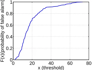
Figure 3.8 Theoretical and measured probabilities of false alarm and false negative when N = 1. . . 36
Figure 3.9 Theoretical and measured probabilities of false alarm and false negative when N = 3. . . 37
Figure 3.10 BitTrickle encoding . . . 38
Figure 3.11 Transmission Errors . . . 38
Figure 3.12 BitTrickle decoding . . . 38
Figure 3.13 Identifying boundaries of a BTmessage . . . 40
Figure 3.14 Probability of merging errors . . . 43
Figure 3.15 Probability of alignment errors . . . 46
Figure 3.16 A Communication Framework of BitTrickle . . . 46
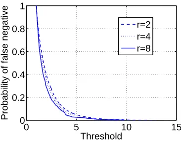
Figure 3.17 False negative/alarm of jamming detector . . . 49
Figure 3.18 False negative/alarm of physical layer authenticator . . . 49
Figure 3.19 Evaluation scenario . . . 50
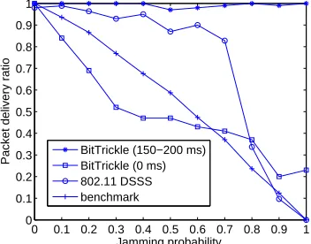
Figure 3.20 Packet delivery ratio . . . 51
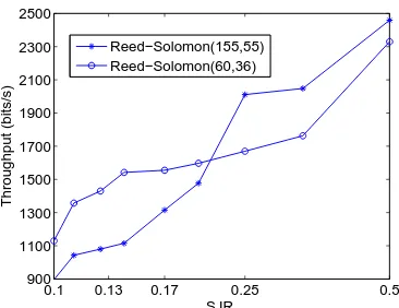
Figure 3.22 Throughput for different coding rate. . . 53
Figure 4.1 Example of a multipath effect. The wireless signal sent by transmitter Tx is reflected by the ionosphere, a building, and the ground. Thus, radio waves prop-agate over paths 1, 2, 3, and 4. The receiver Rx receives signal copiess1,s2,s3, ands4from paths 1, 2, 3, and 4, and the received signal is the sum of all signal copies. . . 55
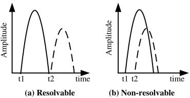
Figure 4.2 Resolvable and non-resolvable multipath components. In (a), the arrivals of two multipath components do not interfere with each other. Therefore, they are resolvable. In (b), the arrival of the second multipath component interferes with that of the first multipath component. Therefore, they are non-resolvable. . . . 55
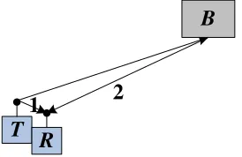
Figure 4.3 Amplitude ratio. T, R, and B is the primary user, the helper node, and an obstacle, respectively. The signal transmitted byTtravels along two paths: path 1 (T → R) and path 2 (T → B → R). LetP1andP2denote the amplitudes of the signal received from path 1 and path 2, respectively. The length of path 1 is much smaller than that of path 2, resulting in a large amplitude ratio P1 P2. . . . 59
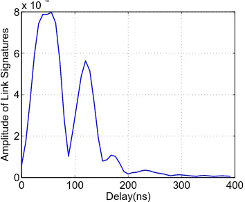
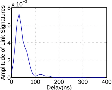
Figure 4.4 Computing the ratior. This graph plots the amplitudes of a real measured chan-nel impulse response (i.e., link signature) obtained from CRAWDAD for a 2.4 GHz channel, andkh1kandkh2kcorresponds the first and the second rounded peak. Therefore,kh1k ≈0.82×10⁻³,kh2k ≈0.55×10⁻³, andr = kkhh2k1k ≈1.49. 61 Figure 4.5 Example of amplitude ratio: The distance between the transmitter and the re-ceiver is 13.77 meters, and the corresponding amplitude ratio is about about 4 2 = 2. . . 62
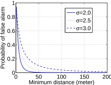
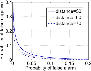
Figure 4.6 Example of amplitude ratio: The distance between the transmitter and the re-ceiver is 1.45 meters, and the corresponding amplitude ratio is about 07.5 = 14. 62 Figure 4.7 Probability of false alarm vs minimum distance from the attacker to the helper node for a constant 0.05 probability of false negative. . . 67
Figure 4.8 Probability of false negative vs minimum distance from the attacker to the helper node for a constant 0.05 probability of false alarm. . . 68
Figure 4.9 Tradeoff between probability of false alarm and the probability of false negative. 68 Figure 4.10 The empirical CDF curve of amplitude ratios computed using primary users’ channel impulse responses . . . 73
Figure 4.11 CDF curves of amplitude ratios computed using attackers’ link signatures. . . . 74
Figure 4.12 Probability of false negative vs threshold . . . 74
Figure 4.13 CDF curves of link differences between the link signatures of primary users and the training sets of secondary users. . . 76
Figure 4.14 Probability of false alarm vs threshold . . . 77
Figure 4.15 CDF curves of link differences between link signatures of attackers and the training sets of secondary users. . . 77
Figure 4.16 Measured link signatures for old position, positiona, and positionb . . . 80
Figure 5.1 The sensor isDmeters away from the receiver . . . 84
Figure 5.2 The sensor is0.4Dmeters away from the receiver . . . 85
Figure 5.5 Training phase protocol . . . 91
Figure 5.6 Normal . . . 95
Figure 5.7 Forgery . . . 96
Figure 5.8 Defense . . . 96
Figure 5.9 Histograms of link difference for the transmitter’s and the attacker’s link signa-tures in normal scenario . . . 96
Figure 5.10 Histograms of link difference for the attacker’s link signatures in forgery and defense scenarios . . . 97
Figure 5.11 False alarm ratePF Aand detection ratePD as a function of threshold . . . 98
Figure 5.12 Tradeoff between false alarm and detection rate for normal, forge, and defense scenarios . . . 98
Chapter 1
Introduction
Wireless communication is ubiquitous today. Various wireless applications like WiFi, bluetooth, and cellular networks have been widely used in people’s daily life. There exist unique security needs in wireless physical layer. For example, wireless medium is exposed to the public, which makes it easy for an attacker to eavesdrop the communication or block the communication by transmitting jamming signals. As another example, an attacker or a selfish user may inject fake signals into the wireless channel to undermine the normal operations of legitimate users. How to protect the physical layer of wireless communication is crucial for applications where reliable information exchange is required. On the other hand, characteristics of wireless physical layer create new opportunities for us to come up with novel and efficient approaches that can guarantee the security of wireless physical layer. Prior work have demonstrated successes in utilizing physical layer properties like radio channel characteristic and modulation errors as fingerprints to authenticate wireless devices [12, 65, 112].
This dissertation includes my four work toward the protection of wireless physical layer. The first and second work propose solutions to combat jamming attacks, which are well known threats to wireless communications. The third work utilize physical layer characteristics to authenticate wireless signal for cognitive radio networks (CRNs), and the last work identifies and addresses vulnerabilities existing in the link signature authentication techniques. Details of those work will be shown in Chapters 2, 3, 4 and 5. In the following, I give the motivations of the four work respectively.
1.1
Randomized Differential Direct Sequence Spread Spectrum
Spread spectrum techniques have been used as countermeasures against jamming attacks. Direct Sequence Spread Spectrum (DSSS), Frequency Hopping Spread Spectrum (FHSS), and Chirp Spread Spectrum (CSS) are three common forms of spread spectrum techniques [68]. In classic spread spectrum techniques, senders and receivers need to pre-share a secret key, with which they can generate identi-cal hopping patterns, spreading codes, or timing of pulses for communication. However, if a jammer knows the secret key, the jammer can easily jam the communication by following the hopping patterns, spreading codes, or timing of pulses used by the sender.
There have been a few recent attempts to remove the dependency of jamming-resistant communi-cations on pre-shared keys [8, 69, 87, 92, 93]. Strasser et al. developed an Uncoordinated Frequency Hopping (UFH) technique to allow two nodes that do not have any common secret to establish a secret key for future FHSS communication in presence of a jammer [92]. Strasser et al. [93] and Slater et al. [87] later independently proposed to use similar coding techniques to improve the robustness and ef-ficiency in UFH. These works successfully remove the requirement of pre-shared keys in point-to-point FHSS communication.
Unfortunately, UFH and its variations [87, 92, 93] cannot be directly used for broadcast commu-nication, since their primary objective is to establish a pairwise key between two parties. Indeed, any spread spectrum communication system that requires a shared key, either pre-shared or established at the initial stage of the communication, cannot be used for broadcast communication where there may be insider jammers. Any malicious receiver, who knows the shared key, may use the key to jam the communication.
To address this problem, researchers recently investigated how to enable jamming-resistant broad-cast communication without shared keys [8, 69]. Baird et al. proposed a coding approach to encode data to be transmitted into “marks” (e.g., short pulses at different times) that can be decoded without any prior knowledge of keys [8]. However, the decoding process of the method is inherently sequential (i.e., the decoding of the next bit depends on the decoded values of the previous bits). Though it works with short pulses in the time domain, the method cannot be extended to DSSS or FHSS without significantly increasing the decoding cost.
P ¨opper et al. developed an Uncoordinated Direct Sequence Spread Spectrum (UDSSS) approach, which avoids jamming by randomly selecting a spreading code sequence from a pool of code sequences. However, as indicated in [69], UDSSS is vulnerable to reactive jamming attacks. It is demonstrated in [69] that when the jammer does not have sufficient computational power to infer the spreading se-quence quickly enough, UDSSS still provides good enough jamming resistance. However, when the jammer has sufficient computational power, UDSSS fails to provide strong guarantee of jamming resis-tance.
vulnerabilities of previous solutions, and thus is a good candidate to enable anti-jamming broadcast communication even when there are potentially compromised or malicious receivers.
RD-DSSS employs spreading codes of traditional DSSS systems to spread a message for reducing the impacts of jamming signals. However, unlike traditional DSSS, RD-DSSS encodes each bit of data using the correlation of unpredictable spreading codes. Specifically, bit “0” is encoded using two different spreading codes, which have low correlation with each other, while bit “1” is encoded using two identical spreading codes, which have high correlation. As a result, sender and receivers do not need to share any common key for communication.
In addition, RD-DSSS uses a pool of spreading code sequences to enhance its reliability and tolerate reactive jamming attacks. A sender spreads each message using multiple spreading code sequences and rearranges the spread result before transmitting it. A receiver, after receiving the entire message, can reverse the rearrangement of the spread result and then recover the original message. However, a jammer has to disrupt the communication at the same time as the message transmission. It is thus very difficult for a jammer to derive the correct spreading sequences on the fly and jam the message transmission accordingly.
1.2
BitTrickle: Wireless Communication under Broadband and High
Power Reactive Jamming
Reactive jamming is one of the most effective jamming attacks [5]. A reactive jammer remains quiet when the target sender is not transmitting, but jams the channel when it detects transmission from the target device. Compared with constant jamming, reactive jamming is harder to track and much more energy efficient [108]. Reactive jamming has been widely used in military applications to cut off the wireless communication among opponent armies or disable the opponent’s use of radio-controlled devices [5].
Current countermeasures against (reactive) jamming attacks mainly rely on spread spectrum tech-niques, which can be categorized as Frequency Hopping Spread Spectrum (FHSS) (e.g., [39, 80, 92, 93, 97]), Direct Sequence Spread Spectrum (DSSS) (e.g., [39, 56, 69, 80, 97]), Time Hopping Spread Spec-trum (THSS) (e.g., [79, 106]), and Chirp Spread SpecSpec-trum (CSS) (e.g., [10, 43, 90]). Among all those spread spectrum techniques, FHSS and DSSS are dominantly used for the purpose of anti-jamming, whereas THSS and CSS require specific hardware (e.g., a pulse/chirp signal generator) [79, 101], and thus are less popular than FHSS and DSSS.
power is not strong enough to overwhelm the DSSS signals with spreading gain, the receiver can use the same pseudo-random sequence to recover the original message.
However, both FHSS and DSSS will fail to protect the communication when attacked by a broad-band jammer who is capable of jamming all frequency channels or a high power jammer who beats DSSS spreading gain. In our work, we endeavor to find a way to enable wireless communication in the presence of such jammers. Ideally, we would like to achieve this anti-jamming purpose without adding specific demands on hardware.
In this dissertation, we develop BitTrickle, a novel communication scheme that allows wireless devices to exchange information when attacked by broadband and high power reactive jammers. Bit-Trickle requires no special hardware. Even wireless devices that are not equipped with spread spectrum capability can employ BitTrickle as a countermeasure against reactive jamming attacks.
BitTrickle achieves the anti-jamming capability by harnessing a subtle opportunity arising from a basic feature of reactive jamming, i.e., “the jammer stays quiet when the channel is idle, but starts transmitting a radio signal as soon as it senses activity on the channel” [111].
Channel sensing is an indispensable function for a reactive jammer to determine if a target sender is transmitting. Channel sensing causes a short time delay. For example, energy detection, the most popular channel sensing approach with very small sensing time [46], requires more than 1 millisecond to detect the existences of target signals for a 0.6 detection probability and -110dBm signal strength level, when implemented in a fully parallel pipelined FPGA (field programmable gate array) architecture for fast speed [15]. Therefore, before the jammer detects the sender’s transmission and starts jamming, the sender has already transmitted one or several bits. As shown in Figure 1.1, though the packet transmitted by the sender is corrupted and cannot be fully recovered, the first few bits of this packet are unjammed due to channel sensing delay∆tat the jammer.
Sender
Jammer
'
t
Figure 1.1: Reactive jamming: The first∆tRbits of the sender’s packet are jamming-free, where∆t andRare channel sensing delay of the jammer and the transmission bit rate of the sender, respectively.
BitTrickle takes advantage of unjammmed bits in corrupted packets to establish jamming-resilient communications. In BitTrickle, the receiver collects bits that are transmitted by the sender but not jammed by the reactive jammer, and assembles them together to construct the original message.
that utilizes modulation properties to identify unjammed bits. In addition, an error recovery mechanism is required to tolerate synchronization errors (e.g., lost bits), and guarantee the performance of traditional error correction codes (ECC). We proposed BitTrickle encoding/decoding techniques, which can locate the original position for each received bit in the original message and enable the use of ECC with high efficiency.
1.3
Authenticating Primary Users’ Signals in CRNs
The proliferation of emerging wireless applications requires a better utilization of radio channels [17]. To address the increasing demand for wireless bandwidth, cognitive radio networks (CRNs) have been proposed to increase the efficiency of channel utilization under the current static channel allocation pol-icy [46]. They enable unlicensed users to use licensed channels on a non-interference basis, thus serve as a solution to the current low usage of radio channels [25]. For example, IEEE 802.22 Standard on Wireless Regional Area Networks (WRANs) employs cognitive radio to allow the sharing of geograph-ically unused channels allocated to television broadcast services, and therefore bring broadband access to hard-to-reach low-population-density areas (e.g., rural environments) [27].
In CRNs, there are two types of users: primary users and secondary users [46]. Primary users are licensed users who are assigned with certain channels, and secondary users are unlicensed users who are allowed to use the channels assigned to a primary user only when they do not cause any harmful interference to the primary user [46]. For example, in IEEE 802.22 WRANs, TV transmission towers are primary users, and radio devices that use TV channels for communication are secondary users.
An essential issue in CRNs is primary user detection, in which a secondary user monitors for the presence of a primary user’s signal on target channels [17]. If a primary user’s signal is detected, the secondary user should not use those channels to avoid interfering with the transmission of the primary user.
Existing methods for primary user detection can be categorized as energy detection and feature detection [46]. In energy detection methods (e.g., [85]), any captured signal whose energy exceeds a threshold is identified as a primary user’s signal. In feature detection methods (e.g., [38,70,78,84,107]), secondary users attempt to find a specific feature of a captured signal, such as a pilot, a synchronization word, and cyclostationarity. If a feature is detected, then the captured signal is identified as a primary user’s signal.
and do not use relevant channels. Such attacks are called primary user emulation (PUE) attacks [17]. It is necessary to have a secure primary user detection method that can identify a primary user’s signal in the presence of attackers. At first glance, a cryptographic signature seems to be a good candi-date for this task. Unfortunately, CRNs face a unique constraint that prevents it from being employed. Specifically, Federal Communications Commission (FCC) states that “no modification to the incumbent system (i.e., primary user) should be required to accommodate opportunistic use of the spectrum by sec-ondary users” [23]. As a result, any solution that requires changes to primary users, such as enhancing primary users’ signals with cryptographic signatures, is not desirable.
There has been a recent attempt that uses a location distinction approach to distinguish between a primary user’s signal and an attacker’s signal [17]. Specifically, this approach uses received signal strength (RSS) measurements to estimate the location of the source of a signal, and then determines if the signal is from the (static) primary user based on the known location of the primary user [17]. However, as indicated in [65], RSS based location distinction can be easily disrupted if an attacker uses array antennas to send different signal strengths in different directions simultaneously. Moreover, it requires multi-node collaboration, which is expensive in terms of bandwidth and energy.
Link signatures (i.e., radio channel characteristics such as channel impulse responses) have been developed recently to obtain more secure and robust location distinction [65, 112]. Unfortunately, it remains non-trivial to exploit link signature based location distinction approach for primary user detec-tion in the presence of attackers. In particular, a receiver needs to know a transmitter’s historical link signatures in order to verify if a newly received signal is from the transmitter. In CRNs, however, it is impossible for a secondary user to know a primary user’s historical link signatures, unless the secondary user can first authenticate whether a signal is from the primary user or not.
In this dissertation, we develop a novel approach that integrates traditional cryptographic signatures and link signatures to enable primary user detection in the presence of attackers. The proposed approach does not require any change to primary users, and thus follows the FCC constraint properly.
1.4
Mimicry Attacks against Wireless Link Signature and Defense using
Time-Synched Link Signature
Wireless physical layer security is becoming increasingly important as wireless devices are more and more pervasive and adopted in critical applications. For example, implantable medical devices (IMD) such as pacemaker may grant access to an external control device only when it is close enough [72], thus making it critical to verify the physical proximity of the control device. There have been multiple proposals recently to provide enhanced wireless security using physical layer characteristics, including fingerprinting wireless devices (e.g., [13]), authenticating and identifying wireless channels (e.g., [65, 112]), and deriving secret keys from wireless channel features only observable to the communicating parties (e.g., [58]).
Among the recent advances in wireless physical layer security is (wireless) link signature. Link sig-nature uses the unique wireless channel characteristics (e.g., the multi-path effect) between a transmitter and a receiver to provide authentication of the wireless channel. Three link signature schemes [53, 65, 112] have been proposed so far. Since its introduction, link signature has been recognized as a wireless channel authentication mechanism for applications where wireless channel characteristics are unique (e.g., [13, 58]).
In this dissertation, we identify a vulnerability of existing link signature schemes [53, 65, 112] by introducing a new attack called mimicry attack. We start our investigation with the link signature scheme in [65], which claimed that an attacker “cannot ‘spoof’ an arbitrary link signature” and that the attacker “will not have the same link signature at the receiver unless it is at exactly the same location as the legitimate transmitter.” However, we show in this dissertation that (1) an attacker can forge an arbitrary link signature as long as the attacker can roughly estimate the legitimate signal at the receiver’s location, and (2) the attacker does not have to be at exactly the same location as the legitimate transmitter in order to forge its link signature. We also extend the mimicry attack to the link signature scheme in [53]. Since the link signature scheme in [112] is essentially an integration of the techniques in [65] and [53], all three link signature schemes are vulnerable to the mimicry attack.
1.5
Summary of Contributions
The contributions of this dissertation are summarized below:
• RD-DSSS: First, we develop a new DSSS based anti-jamming scheme to both remove the require-ment of shared keys for DSSS communication and overcome the weaknesses of previous solutions (e.g., vulnerability to reactive jamming attacks). Second, we evaluate the performance and effec-tiveness of RD-DSSS in presence of various kinds of jamming attacks through both theoretical analysis and simulation.
• BitTrickle: We address the problem of anti-jamming wireless communication under high power broadband reactive jamming, where the previous approaches all fail. We develop the BitTrickle anti-jamming communication scheme by taking advantage of the reaction time of the jammer, thus allowing wireless communication even when all previous anti-jamming techniques fail. We develop solutions to two technical challenges in the development of BitTrickle. First, we develop a high quality jamming detector that utilizes modulation properties to precisely distinguish un-jammed bits from un-jammed bits. Second, we develop a novel encoding/decoding technique that can successfully recover a transmitted message from message fragments that partially survive reactive jamming. We implement a working prototype of BitTrickle based on GNURadio [1] and evaluate it on Universal Software Radio Peripherals (USRPs) [57]. We also compare it with 802.11 DSSS and a benchmark program, both provided in GNURadio, in terms of packet delivery ratio and throughout. Our experimental results show that the BitTrickle prototype achieves a rea-sonable throughput that enables message exchange between victim wireless devices when 802.11 DSSS and the GNURadio benchmark is completely disabled by a reactive jammer.
Chapter 2
Randomized Differential Direct Sequence
Spread Spectrum
2.1
Background on DSSS
DSSS is a modulation method applied to digital signals [40]. It increases the signal bandwidth to a value much larger than needed to transmit the underlying information [40]. In DSSS, spreading codes that are independent of the original signal are used to achieve the goal of bandwidth expansion. Both a sender and a receiver agree on a spreading code, which is regarded as a shared secret between them. A spreading code is usually a sequence of bits valued1and −1(polar) or1and0(non-polar), which has noise-like properties. Without loss of generality, we consider spreading codes with polarity. Typical spreading codes are pseudo-random codes, Walsh-Hadamard codes and Gold codes [86]. Figure 3.16 shows a simple communication framework of DSSS.
D/A Spreading output
…+1-1+1-1-1+1-1... Square waveform Cosine signal
(carrier)
A/D Sampler
and Detector
Received message Noise/Jamming corrupted square waveform
Cosine signal (carrier)
Jammer
noise Radio frequency
signal
Spread
De-spread Original message
from the sender ...1011...
...1011... Reconstructed message at the
receiver
ECC Encoder
ECC Decoder
Encoded mesage ...10101...
De-spreading output
...00101... …+1-1+1-1-1+1-1...
Transmission Process: A sender usually first encodes the original message using an error correction code (ECC) to enhance the reliability of the communication. The sender then uses DSSS to spread the encoded message into a binary bitstream called chips, and uses a D/A converter to transform the chips into analog square wave signal called baseband signal. The baseband signal is multiplied by a cosine signal with a certain frequency, resulting in the RF signal. The RF signal is fed to the antenna to transmit in the wireless channel.
Reception Process: Upon hearing the RF signal, the receiver performs similar tasks in the reverse order. The receiver first recovers the baseband signal by multiplying a cosine signal as used by the sender, applies an A/D sampler and a detector to transform the baseband signal into chips, and uses DSSS to de-spread the chips. The receiver finally decodes the de-spread result to reconstruct the original message.
Spreading and De-spreading: Spreading and de-spreading are two important functions of a DSSS system. In spreading, a sender multiplies each bit of the original message with a spreading code to get the spread message. For example, if the original message is “01” and the spreading code is−1+1+1−1, then the sender converts the original message “01” into the polar form−1+1, and multiplies−1and+1
with spreading code−1+1+1−1, respectively. The spread message is thus+1−1−1+1−1+1+1−1. It is necessary to understand the notion of correlation to see how de-spreading works. Given two spreading codesf =f1, .., fkandg =g1, .., gk, wherefi andgi are valued−1or 1 for1≤i≤k, the correlation offandgisf·g= k1Pk
i=1figi. Note that the correlation of two identical codes is 1. In de-spreading, the receiver uses a local replica of the spreading code and synchronizes it with the received message [86]. Then the receiver correlates the received message with the replica to generate the de-spreading output. For example, suppose the received message is+1−1−1 + 1−1 + 1 + 1−1
and the local replica of the spreading code is−1 + 1 + 1−1at the receiver side. The receiver aligns −1 + 1 + 1−1with the first 4 chips of the received message (i.e.,+1−1−1 + 1) and correlates them to get bit−1(i.e., “0” in non-polar form).
Synchronization: In DSSS systems, a receiver needs to identify the beginning of a message sent by the sender from the received signal. In general, the sender and the receiver agree on a known code such as Barker Code [9] that has good autocorrelation property (i.e., the correlation between a code and its shifted value is low). The sender transmits the code just before the spread message. The receiver correlates the received signal with the code using a sliding window approach; the position where the correlation is maximum indicates the beginning of the message [21, 41, 86].
2.2
System and Threat Models
Our system consists of a sender and multiple receivers. The sender and receivers are wireless devices that can transmit and receive RF signals. We assume that there are jammers that inject noise signals into the wireless channel. The goal of the jammers is to prevent communication between the sender and the receivers. We assume a jammer has the following capabilities: (1) He is aware of the target commu-nication systems (e.g., protocols and anti-jamming strategy); (2) he can eavesdrop the commucommu-nication between the sender and the receivers; (3) he can transmit on the wireless channel to interfere with the physical transmission and reception of the desired wireless signals; (4) he can inject fake messages into the channel; and (5) he can perform real-time analysis to identify the spreading code used to spread each bit data right after its transmission. However, we assume that if a jammer does not know the code for spreading any 1-bit data, he cannot jam the transmission of it.
2.3
Randomized Differential DSSS
Similar to traditional DSSS, RD-DSSS takes advantage of the correlation properties of spreading codes to achieve anti-jamming communication. The transmission, reception, and synchronization of a RD-DSSS system are the same as those of a traditional RD-DSSS system except for the spreading and de-spreading processes. Due to the change in these processes, RD-DSSS does not require a sender and its receivers to share a secret key. In the following, we focus on spreading and de-spreading processes of RD-DSSS.
2.3.1 Basic Scheme
In RD-DSSS, the sender and the receivers share a set of spreading codes, which we call the spreading code set. There should be low correlation between any two codes in the spreading code set. A sender encodes each bit of data using the correlation of two unpredictable spreading codes. Specifically, bit “0” is encoded using two different spreading codes, which have low correlation with each other, while bit “1” is encoded using two identical spreading codes, which have high correlation. A sender can randomly choose different pairs of codes from the code set for different bits in a message. A receiver de-spreads a received message by computing correlation of the two codes for each bit. High correlation and low correlation are translated into “1” and “0”, respectively.
Figure 2.2 shows an example, in which a sender transmits a 4-bit message “1011” to a receiver. The sender randomly chooses codes p1, p4, p5, and p7 from the spreading code set. Since bit 1 of
the message is “1”, the sender uses p1 twice to encode it. The second bit of the original message
is “0”. Thus, the sender uses any code different from p4 (i.e., p3 as shown in Figure 2.2) and p4
to encode it. Bits 3 and 4 are encoded similarly. As a result, the sender gets an encoded message
code set
original message 1 0 1 1
spreading p1 p3 p5 p7 p1 p4 p5 p7
1
p p3 p5 p7
4
p
1
p p5 p7
spread message a sequence of codes
de-spreading
correlations H L H H
spread message sequence of codes
index code set 1 2
{p , p ,...}
1 2
{c , c }
1 1 4 5 7
2 6 3 8 9
c : p || p || p || p ,
c : p || p || p || p ,
replaced with c1
bit 1 bit 2 bit 3 bit 4
Figure 2.2: An example of the basic RD-DSSS scheme.
sender earlier. For de-spreading, the receiver computes the correlations between the corresponding codes in the first and the second halves of the spread message (i.e.,p1·p1,p3·p4,p5·p5, andp7·p7).
High correlation and low correlation are translated into “1” and “0”, respectively.
To reduce the communication overhead, we propose to have the sender and the receivers share a set of pre-defined spreading code sequences, which are formed by the concatenations of codes in the spreading code set. We associate each code sequence with a special spreading code called index code. The collection of all index codes is referred to as the index code set. We require that the correlation between two different index codes is low. Intuitively, a sender can transmit an index code (instead of the actual code sequence) to indicate the code sequence for spreading. For example, Figure 2.2 shows that there are two code sequences, which are represented by index codesc1 andc2, respectively. Instead of
sending p1||p4||p5||p7 as the second half of the spread message, the sender simply transmitsc1. The
index code set and the spreading code set should have no overlap so that a receiver can easily distinguish between an index code and a regular spreading code.
In the following, we present the basic scheme in detail.
Code Set and Code Sequence Set
LetP = {p1, ...,pn}denote the spreading code set withncodes. As mentioned earlier, these codes should have low correlation with each other. There are multiple candidate codes for our scheme, such as Gold codes, Walsh-Hadamard codes, m sequences, and Kasami codes [86]. We assume each code in P is of lengthf andP is publicly known.
public.
To reduce storage overhead, we only store the index codes and generate each code sequence inC using its index code. One possible way is to use a pseudo-random generator (PRG) withcias the input to generate a sequence of indexes, which are then used to select codes fromPto form a code sequence. For example, assume ci is the index code ofpi1||pi2, n = 4, and P RG(ci) = (01 11...)2. Thus, pi1=p1andpi2 =p3.
Spreading
Letm =m1||...||ml denote the original message to be transmitted. For spreading, a sender randomly chooses a code sequence fromC. LetS =s1||...||sl denote the chosen code sequence. The sender then generates the spread message based on the chosen code sequenceS. LetF=f1||...||fldenote the spread message. For1 ≤ i ≤ l, the sender generates fi according to the following rule: ifmi = 1,fi is the same assi. Otherwise,fiis an arbitrary code inP other thansi. Assume the index code of the chosen code sequence isc. The sender appendsc to the end of the spread message and transmitsF||cto the receiver.
De-spreading
For de-spreading, a receiver needs to identify the chosen code sequence. Suppose the received message is Fˆ||ˆc, where Fˆ = ˆf1||ˆf2||...||ˆfl. The receiver computes correlations between each index code and
ˆ
c. Note that the correlation between two identical codes is the highest and reaches correlation peak. Thus, the receiver marks the index code that results in the highest correlation withˆcas identified. Let
S=s1||s2||...||sldenote the code sequence associated with the identified index code. The receiver then usesSto de-spread the received message.
To de-spread the received message, a receiver needs to compute the following correlations: (ˆf1·s1),
(fˆ2·s2),..., (ˆfl·sl). Letmˆ = ˆm1||...||mˆldenote the de-spreading output. mˆ can be generated according to the following rule: if(ˆfi·si)is larger than or equal to a thresholdt,mˆi= 1. Otherwise,mˆi = 0.
The threshold t is an important parameter. We derive the threshold tas the value that minimizes the probability of decision error when the transmitted signal is polluted by additive white Gaussian noise signal, which is a generally assumed jamming signal in wireless communications [86, 97]. This threshold is given in lemma 1.
Lemma 1 Given additive Gaussian noise, the probability of decision error is minimized for threshold t= 12(1 +ρ), whereρ= 1
(n
2)
P
∀pi,pj∈P(pi·pj)(i.e.,ρis the average of the correlations between two
codes inP).
assume the elements ofniare independent and identically distributed (i.i.d) Gaussian random variables with mean value 0 and varianceσ2. Lete = (e1, ..., el) denoteX −Xˆ, where ei = xi−xˆi, and let
si =si1||si2||...||sif, wheresij is valued−1or+1. Note thatxˆi = ˆfi·si= (fi+ni)·si=xi+ni·si. Thus,ei =ni·si = f1Pfj=1nijsij. According to the properties of Gaussian variables [62],ei is i.i.d. Gaussian random variables with mean value 0 and varianceσ2.
Whenmi = 1,xˆi =xi+ei = 1 +ei. The probability density function (pdf) of1 +eiisf1(ˆxi) =
1
√
2πσe
−(ˆxi2−σ21)2. Whenm
i = 0,xˆi = xi+ei = ρ+ei, the pdf ofρ+ei isf0(ˆxi) = √21πσe− (ˆxi−ρ)2
2σ2 .
Assume the sender transmits “1” or “0” with probability 12. Thus, the probability of decision error is pe = 12(R−∞t f1(ˆxi)dxˆi+Rt∞f0(ˆxi)dxˆi) = 12(1 +12erf(√t−21σ)− 12erf(√t−2ρσ)), whereerf is the Error Functionerf(w) = √2πR0we−y2
dy[86].
To minimize pe, we let the derivation ofpe be 0 (i.e.,dpdte = 0) and solves t. We can obtaint =
1
2(1 +ρ)and the minimized probability of decision error ispemin= 12 +12erf(
ρ−1
2√2σ).
Pros and Cons
The basic scheme of RD-DSSS provides resistance against wireless interference for broadcast commu-nication. The sender randomly chooses a code sequence to spread each original message, and no one except for the sender knows the code sequence before the communication. Thus, the requirement of shared keys is removed, gaining reliability and scalability for broadcast communication systems. Fur-thermore, the sender associates an index code with each code sequence and transmits the index code instead of the actual code sequence. Thus, the communication overhead is reduced.
However, the basic scheme is still vulnerable to reactive jamming attacks. Recall that bit “1” is encoded by two identical codes. Thus, the spread message and the chosen code sequence may share many similar codes, and the correlation between them may be high. After observing the firstr codes of a message being transmitted, the jammer can compute the correlation between the observedr codes and the firstrcodes of each code sequence inC. The code sequence resulting in the highest correlation is probably the code sequence chosen by the sender. The jammer can then spread a fake message using the identified code sequence to jam the transmission of the remaining message.
2.3.2 Enhanced Scheme: Defending against Reactive Jamming
The basic scheme is vulnerable to reactive jamming attacks, since the correlation between the spread message and the chosen code sequence is usually high. In the enhanced scheme, we propose two mechanisms to reduce the correlation and improve the basic scheme.
Assume the correlation between two different codes is 0. Thus, the correlation between the spread message and the chosen code sequence is1+0+1+14 = 0.75. However, if we permute the spread message and assume the result is p7||p5||p1||p3, then the correlation between the permuted spread message
and the chosen code sequence is reduced to 0. Second, the sender spreads the message using kcode sequences in C. As a result, a reactive jammer must know all k code sequences in order to launch reactive jamming successfully.
In the following, we present the enhanced scheme in detail.
Spreading
A sender randomly chooses kcode sequences from C and uses them to generate the spread message. Suppose code sequencesci1 = pi11||...||pi1l, ...,cik = pik1||...||piklare selected. For1 ≤ j ≤ l, let
Aj ={pi1j, ...,pikj}. That is,Aj consists of thej-th codes of all chosen code sequences. The sender
generates the spread messageF=f1||f2||...||fl according to the following rule: Ifmj = 1, choosesfj as any code inAj randomly. Otherwise, choosesfjas any code not inAj.
The sender then maps each setAjto an integer number and sorts those numbers in descending order to generate a permutation. For example, leth(Aj)denote the mapping function that converts setAj into an integer. Assumel = 3(i.e.,F =f1||f2||f3), andh(A1) = 55, h(A2) = 67, andh(A3) = 23.
The sorting result ish(A2), h(A1), h(A3), and thus we usef2||f1||f3as the permuted message.
Given Aj = {pi1j, ...,pikj}. We simply compute h(Aj) as h(Aj) = ind(pi1j) ×10k−1 + ind(pi2j)×10
k−2...+ind(p
ikj), whereind(p) is the index of the code p. For example, if k = 2
andAj ={p3,p1}, thenh(Aj) = 31.
Finally, the sender appends index codesci1, ...,cik to the end of the permuted spread messageFp,
and transmitsFp||ci1||...||cik to the receivers.
De-spreading
A receiver recovers the original message in two steps: (1) identify the index codes appended by the sender, and (2) process the received message.
Let Fˆp||ˆci1||...||ˆcik denote the received message, whereFˆp is the permuted spread message and
ˆ
ci1, ...,ˆcik are the index codes. The receiver needs to identify the index codes that are appended by the
sender. For1≤u ≤ k, the receiver computes the correlations between each index code andˆciu(i.e., c1·ˆciu, ...,cq·ˆciu). The index code that results in the highest correlation withˆciuis marked as
identi-fied. Letci1′, ...,ci
k′ denote the identified index codes andpi1′1||...||pi1′l, ...,pik′1||...||pik′ldenote the
corresponding code sequences, where1 ≤i1′, ..., ik′ ≤q. For1 ≤ j ≤l, letA′j ={pi1′j, ...,pik′j}.
The receiver computes the permutation based onh(A′
Ability to Deal with Reactive Jamming
To perform reactive jamming attacks, a jammer needs to find code sequences used for message trans-mission. However, the correlation between the observed codes and any of code sequences chosen by the sender is not guaranteed to be high, since the code order in the spread message is rearranged.
The jammer may do an exhaustive search over all possible combinations ofkcode sequences inCto find those chosen by the user. The number of correlations the jammer should compute isk kq
. However, even with all the correlation results, the jammer still cannot determine which code sequences have been chosen, because (1) transmission of bit “0” can use any code other than those in the corresponding position of the selected code sequences and (2) multiple code sequences could be used for encoding. Moreover, the jammer must finish the computation within the transmission time of a single message in order to launch reactive jamming. For example, ifq = 13,500and k= 5, the number of correlations the attacker needs to compute is5× 13,5500
>264. Assume the length of the original message is1,024
bits and that of a spreading code is 256 chips. For a 802.11 wireless device with 11 Mbps data rate, the time for transmitting a spread message is 1,11024××102566 ≈0.024 second. This means the jammer must finish such a huge amount of computation within 0.024 second. We provide detailed analysis to show the effectiveness of RD-DSSS in tolerating reactive jamming attacks in Section 2.5.2.
2.4
Performance Overheads
Computational Overhead: RD-DSSS systems require additional operations compared with traditional DSSS systems (e.g., computing correlations to identify index codes). Letth,ts,tp,tip, andtc denote the computation time for performing mapping functions, sorting, permutation, inverse permutation, and computing correlations to identify index codes. The additional computation overheadtaintroduced by RD-DSSS ista=th+ts+tp+tip+tc.
To get an intuitive feeling of the computational overhead, we did an experiment to test the time required by these additional operations. The system settings in the experiment are as follows: The message length is 1,024 bits, the size ofP is 100, the size ofCis 13,500, the length of each index code is 512 chips, the number of code sequences chosen by the sender is 3, and the length of each code inP is 256 chips. Table 2.1 shows the computation time of those operations performed on a computer with a 3.40 GHz Intel Pentium 4 CPU and 1.5 GB memory. All those operations together can be finished within 15 milliseconds. In practice, the correlation operation is inherently parallel (i.e., dot product of two vectors) and be finished efficiently with special purpose hardware.
Note that a reactive jammer must compute 3× 13,3500
Table 2.1: computation time (milliseconds)
Operations # of computations computation time
Mapping 1,024 th= 0.114
Sort 1 ts= 4.654
Permutation 1 tp= 0.005
Inverse Permutation 1 tip= 1.100
Correlation 13,500×3 tc= 8.989
Total 41527 ta= 14.862
tj = 3×( 13,500
3 )×tc
13,500×3×100 and r =
3×(13,3500)×tc
13,500×3×100×(th+ts+tp+tip+tc). In particular, using the parameters in
Ta-ble 2.1, we can get the overheadtj= 2,729.8seconds, which is much larger than the transmission time of a single message, and the ratior = 183,680. Whenkincreases, the jammer’s computation overhead tj increases exponentially, since the jammer needs to check all combinations ofkcode sequences inC (i.e.,k kq
). However, the receiver’s computation overheadtaincreases linearly, since the receiver only needs to checkk×qcorrelations for identifying the index codes.
Storage Overhead: RD-DSSS systems need to store the code set P and all the index codes. In our experiment, the number of index codes is13,500. Assume the size ofPis 100. Thus, the required storage capacity is100×256 + 13,500×512bits= 0.83MB, which can be afforded by notebook- or handheld-class devices nowadays.
Communication Overhead: RD-DSSS systems slightly increase communication overhead com-pared with traditional DSSS systems, since a sender needs to appendkindex codes to the end of the message body. However, this communication overhead is negligible compared with the cost of trans-mitting the message body. For example, in the settings of the earlier experiment, the communication overhead introduced by the index codes is3×512chips for each message, which has256×1,024chips. The overhead is less than0.6%.
2.5
Security Analysis and Simulation
We perform theoretical analysis to show the effectiveness of RD-DSSS in defending against various jamming attacks. We also perform simulation to confirm our analytical results. The simulation is done in MATLAB 7.4.0 on a computer with a 3.40 GHz Intel Pentium 4 CPU and 1.5 GB memory.
2.5.1 Classification of Jamming Attacks
signals to cause wireless interferences. They differ from each other in energy distributions of their jamming signals. In practice, there exist more complicated jammers. For example, a “smart” jammer can not only transmit random noise signals, but can also inject fake messages that are encapsulated in the packet format used by the communicators to mislead the reception process [111].
Based on the previous work [86, 111], we generalize jamming attacks into two categories: non-intelligent jamming attacks and non-intelligent jamming attacks. In the former attacks, the jammer disrupts wireless communication by sending random noise signals. In the latter attacks, the jammer transmits jamming signals that are generated based on his knowledge of the communication systems (e.g., the signal patterns, anti-jamming strategies, and communication protocols).
Note that conventional DSSS is capable of mitigating non-intelligent jamming attacks [86]. There-fore, inheriting from conventional DSSS, RD-DSSS is also non-intelligent jamming resilient. Thus, in this section, we focus our analysis on the intelligent jamming attacks.
2.5.2 Intelligent Jamming Attacks
In intelligent jamming attacks, a jammer is aware of the target communication systems and transmits meaningful messages to undermine the communication. In RD-DSSS systems, a significant threat caused by intelligent jamming attacks is that a jammer may take advantage of the publicly known spread-ing code setP, code sequence setC, and the index code setIto jam the communication. Therefore, in our analysis, we focus on the ways that an intelligent jammer can use the publicly known information to disrupt the wireless communication.
By exploiting P,C, andI, an intelligent jammer can choose the following strategies to attack RD-DSSS systems:
• Type I: He can randomly choose codes fromPand tries to jam the communication by transmitting those spreading codes.
• Type II: He can perform reactive jamming discussed in Section 2.3.1. That is, the jammer tries to find the code sequences used by a sender by analyzing the first portion of a message being transmitted, and then spreads a fake message using the identified code sequence to jam the rest of the message transmission.
• Type III: He can perform Denial of Service (DoS) attacks targeting the index codes, in which he randomly picks several index codes and transmits them along with the legal index codes to force receivers to deal with a large number of candidate index codes.
Type I Attacks
In Type I attacks, the jammer randomly selects codes fromP, and transmits them to interfere with the original message transmission. We first derive the probability that the jammer can disrupt the wireless communication.
Analysis: Suppose thei-th code transmitted by the sender ispi andAiis the set that generates the
i-th code of the permuted spread message. If the bit spread byAi is “0” and pi happens to be inAi, then the receiver cannot de-spread the original bit correctly. However, a few bit errors can be tolerated by ECC. For example, the standard (255, 223) Reed-Solomon code is capable of correcting up to 16 bit errors among every 223 information bits of a message [103]. If the ECC can correct a maximum of M bit errors of the original message but the jammer can collapse more than M bits, then the receiver cannot reconstruct the original message. In the following, we derive the probability that the jammer can disrupt the transmission of a message (i.e., the probability that the jammer can jam more thanM bits).
Assume the sender transmits “1” or “0” with probability 12. Let|Ai|be the number of codes in the setAi. The probability that thei-th code transmitted by the jammer is one code inAiisP(pi∈ Ai) =
Pk
j=1P(|Ai|=j)nj, wherenis the size of the code setP.
The number of ways of picking jcodes fromP is nj, and the number of ways of puttingkcodes fromP intoAiisnk. LetN(j)denote the number of ways of puttingjdistinct codes intoAisuch that |Ai|=j. Thus, the recurrence equation of N(j)isN(j) =jk−Pjw=2 wj−1
N(w−1). According to classical probability model, P(|Ai| = j) = (
n j)N(j)
nk . Thus, P(pi ∈ Ai) =
Pk
j=1
(n j)N(j)j
nk+1 and the probability that the bit spread byAi is jammed is P(pi2∈Ai). Therefore, the probability that more than M bits are corrupted by the jammer (i.e., the probability that the communication is jammed) is pJ =Pli=M+1 li
(P(pi∈Ai)
2 )
i
(1−P(pi∈Ai)
2 )
l−i .
Figures 2.3 shows the jamming probability pJ when each message has 1,024 bits. It is easy to see that pJ decreases as the size of the spreading code set (n) increases. When n is larger than 70 and
M = 60, the probability is less than10−4.
Simulation: We use simulation to further examine the effectiveness of RD-DSSS and confirm the theoretical results. In the simulation, the length of the message is 1,024 bits and the size ofCis 10,000. We letM = 60andnrange from 50 to 60. For eachn, we randomly generate a message and spread it using 5 code sequences randomly selected from C. We also form the jammer’s code sequence by randomly pickinglcodes fromP. Then we count the number of bits that can be disrupted by the jammer, and mark the trial as successful if the number is larger thanM. We repeat this process for 1,000 times and estimate the simulatedpJ(i.e., the probability that a message is jammed) aspJ = #successf ul trails#trials . Figure 2.4 shows both the simulated and the theoretical probabilities whenM = 60. We can see that both probabilities are less than 0.01 if the size of the code set is larger than 60.
20 40 60 80 100 10−10
10−8 10−6 10−4 10−2 100
Size of code set
Probabilities of being jammed (k=5)
M=30 M=40 M=50 M=60
Figure 2.3: Theoretical probability that an attacker jams communication fork= 5
50 52 54 56 58 60
0 0.02 0.04 0.06 0.08
Size of code set
Probabilities of being jammed (M=60)
theoretical simulated
Figure 2.4: Simulated and theoretical probabilities that an attacker jams communication whenM = 60
25 30 35
0 0.05 0.1 0.15 0.2 0.25
Number of bit errors ECC can tolerate
Probabilities of being jammed (n=120)
theoretical simulated
change the number of bit errors ECC can tolerate. We can see that both probabilities decrease as the number of bit errors ECC can tolerate increases. WhenM = 35, the jamming probabilities are less than 0.01.
Type II Attacks
We now evaluate the feasibility of reactive jamming attacks. We use the correlation between the jam-mer’s observation and each code sequence inCas the evaluation metric. In other words, we assess the possibility for a jammer to gather enough information for reactive jamming.
In reactive jamming attacks, a jammer infers the code sequences chosen by the sender based on the first few codes that have already been transmitted by the sender, and then uses the identified code sequences to jam the transmission of the rest codes. However, in RD-DSSS the sender permutes each spread message before transmission. Thus, the correlation between the transmitted message and the code sequences chosen by the sender is reduced, and it is hard for the jammer to correctly identify the code sequences chosen by the sender by analyzing the correlation between the observed codes and each code sequence inC.
In the following, we derive the correlation between the observed codes and a code sequence not selected by the sender. We also derive the correlation between the observed codes and a code sequence selected by the sender. We then compare both correlations and show that they are very close to each other.
Analysis: Letp1 andp0 denote the probability that the sender transmits “1” and “0”, respectively.
Let f = f1||...||fr denote the r codes transmitted by the sender and observed by the jammer, where
1≤r≤l. Letg=g1||...||gldenote a code sequence not selected by the sender. Assumep1 =p0 = 12.
The probability thatfi=giis given in Lemma 2 Lemma 2 The probability thatfi =gi is21n+2n1k
Pk
j=1 nj
N(j)n(jn(−n1)−jj).
Proof: Assume the original position offiisio. Ifmio = 1, the probability thatfi =giis
Pk
j=11jP(|Aio|= j)nj = n1. Ifmio = 0, the probability thatfi =giis
Pk
j=1 n1−jP(|Aio|=j)(1− 1
n)j. Hence,
P(fi=gi) = 21n+12Pjk=1n1−jP(|Aio|=j)(1− 1
n)j =
1 2n +
1 2nk
Pk
j=1 nj
N(j)n(nj(−n1)−jj).
Leth = h1||...||hl denote a code sequence selected by the sender. The probability thatfi = hi is given in Lemma 3
Lemma 3 The probability thatfi =hiis1l((2n1k
Pk
j=1 nj
N(j)(1j−n(nj(−n−1)jj)))−21n)+21n+2n1k
Pk
j=1.
Proof: Ifi = io (i.e., theio-th code of the original spread message does not change its position after permutation), the probability that thei-th observed codefi is the same ashi isP(fi = hi|i = io) =
1 2
Pk
j=1P(|Aio|= j) 1
j = 2n1k
Pk
j=1 nj
Therefore, P(fi =hi|i6=io) =P(fi =gi). For1 ≤io, jo ≤ l, the probability thatAio =Ajo is
1/ nk
, which is a very small value ifnis relatively large andkis relatively small (e.g.,1/ nk
≈10−7
when n = 50and k = 5). Therefore, the probability thatAio = Ajo is approximately 0. Note that
for different inputs, the outputs of mapping functionhare also different. Thus, the possible values of h(A1), ..., h(Al)are distinct from each other. We considerh(A1), ..., h(Al)aslrandom variables. The probability thath(Aio)is just theio-th smallest/largest element among all values is
1
l. Therefore, the probability thati= io is 1l and the probability thati6= io is1− 1l. As a result, P(fi =hi) =P(i=
io)P(fi =hi|i=io) +P(i6=io)P(fi =hi|i=6 io) = 1l((2n1k
Pk
j=1
n j
N(j)(1j −n(jn(−n−1)jj)))−21n) + 1
2n+2n1k
Pk
j=1.
0 20 40 60 80 100
0.02 0.04 0.06 0.08 0.1 0.12
Length of a message
Correlations with the observed codes
unselected code sequences selected code sequences
Figure 2.6: E(f·h)andE(f ·g)(k= 5,n= 30)
50 60 70 80 90 100
0.01 0.012 0.014 0.016 0.018 0.02 0.022
Size of code set
Correlations with the observed codes
selected code sequences unselected code sequences
0 20 40 60 80 100 0
0.02 0.04 0.06 0.08 0.1 0.12
Length of a message
Correlations with the observed codes
simulated n=30 theoretical n=30 simulated n=50 theoretical n=50 simulated n=80 theoretical n=80
Figure 2.8: Simulated and theoreticalE(f ·h)forn= 30,n= 50, andn= 80
0 20 40 60 80 100
0.02 0.04 0.06 0.08 0.1 0.12
Length of a message
Correlations with the observed codes
unselected code sequences selected code sequences
Figure 2.9: E(f·h)andE(f ·g)(k= 5,n= 30)
Assume that the correlation of two identical codes is 1 and that of two different codes is 0. Based on Lemmas 2 and 3, the expectation of the correlation between f1||...||fr and g1||...||gr is E(f ·g) =
1
r
Pr
i=1P(fi = gi) = P(fi = gi), and the expectation of the correlation between f1||...||fr and h1||...||hrisE(f·h) = 1rPir=1P(fi =hi) =P(fi=hi).
Figure 2.9 shows the expectation of the correlation between the observed codes and a code sequence selected by the sender (i.e.,E(f·h)), as well as the expectation of the correlations between the observed codes and a code sequence not selected by the sender (i.e.,E(f·g)). We can see thatE(f·h)approaches