Volume 2008, Article ID 743202,14pages doi:10.1155/2008/743202
Research Article
Edge Segment-Based Automatic Video Surveillance
M. Julius Hossain, M. Ali Akber Dewan, and Oksam Chae
Image Processing Lab, Department of Computer Engineering, Kyung Hee University, Yongin 446-701, South Korea
Correspondence should be addressed to Oksam Chae, [email protected]
Received 22 February 2007; Revised 26 June 2007; Accepted 1 October 2007
Recommended by Ovidio Salvetti
This paper presents a moving-object segmentation algorithm using edge information as segment. The proposed method is de-veloped to address challenges due to variations in ambient lighting and background contents. We investigated the suitability of the proposed algorithm in comparison with the traditional-intensity-based as well as edge-pixel-based detection methods. In our method, edges are extracted from video frames and are represented as segments using an efficiently designed edge class. This rep-resentation helps to obtain the geometric information of edge in the case of edge matching and moving-object segmentation; and facilitates incorporating knowledge into edge segment during background modeling and motion tracking. An efficient approach for background initialization and robust method of edge matching is presented, to effectively reduce the risk of false alarm due to illumination change and camera motion while maintaining the high sensitivity to the presence of moving object. Detected moving edges are utilized along with watershed algorithm for extracting video object plane (VOP) with more accurate boundary. Experi-ment results with real image sequence reflect that the proposed method is suitable for automated video surveillance applications in various monitoring systems.
Copyright © 2008 M. Julius Hossain et al. This is an open access article distributed under the Creative Commons Attribution License, which permits unrestricted use, distribution, and reproduction in any medium, provided the original work is properly cited.
1. INTRODUCTION
Moving object segmentation is of important research interest for widespread applications in diverse disciplines. The seg-mentation in automated video surveillance isolates the events of potential interest from a large volume of redundant image data, since human observers may easily be distracted from this task. Potential events are extracted by detecting motion information in the sequence. A basic motion detection al-gorithm takes in an image sequence as input, detects frames having significant change from the previous frames or back-ground image and extracts the significantly changed regions [1]. Motion is subjectively an important element of the video signal as it can successfully extract VOPs in video frames. With adaptation to motion, content-based image analysis and more efficient signal processing algorithms can be de-signed to improve the picture quality. Motion adaptive al-gorithms have been successfully implemented in numerous video applications, such as standard conversion, noise reduc-tion, Y/C separareduc-tion, and video coding.
Ideally, motion is detected due to the changes resulted from appearance or disappearance of objects and movement of objects relative to the background. Stationary objects can
also undergo changes in brightness or color due to illumi-nation variation, camera motion, nonuniform attenuation, atmospheric absorption, or camera calibration error [1,2]. However, moving object detection system should not de-tect these unimportant or nuisance forms of change. The challenges for existing approaches include some phenomena, like dynamic background (foreground can temporarily act as background), partial occlusion, high traffic [1,3]. As a result, some part of the background is detected as moving object and vice versa.
(a) (b)
(c) (d)
Figure1: Pixel and segment-based representation of edges. (a) Edge image of a scene. (b) Edge image of the same scene at different time. (c) Result obtained through pixel-based matching. (d) Result ob-tained through segment-based matching.
Moreover, edge information is less sensitive to noises and is more consistent than the pixel values in the video sequence. However, traditional edge pixel-based moving object detec-tion methods do not represent edge informadetec-tion using any data structure and thus they need visiting all the image loca-tion to access edge points [8–10]. These methods treat each edge point independently which is not convenient for match-ing and trackmatch-ing. It is also very difficult to handle dynamic background where foreground can temporarily act like back-ground for an arbitrary period of time.
In the proposed method, we extract the edge informa-tion from video frame and represent them as segments us-ing an efficiently designed edge class [11]. We do not handle each edge pixel independently rather all the points belonging to a segment are considered as a unit and are processed to-gether. Segment-based representation using edge class helps to access edge pixels fast as we do not need to access all the pixels in the image. Once represented, detection and update can be performed by using edge list, without accessing in-put frame. This representation helps to incorporate an effi -cient and flexible edge matching algorithm. During match-ing, decision about a complete edge segment is taken instead of an individual pixel. It reduces the occurrence of scattered edge pixels in the detection result.Figure 1shows the rela-tive advantages of edge segment-based matching over edge pixel-based matching. Figures1(a)and1(b)are two edge im-ages having slight variations.Figure 1(c)shows the result ob-tained by pixelwise matching where allowable distance vari-ation is set to 2. Figure 1(d) shows the result obtained by segment-based method with the same allowable average dis-tance. In the case of pixel-based matching, about 20 percent edge pixels are missed.
Once we construct the edge segment from the edge pix-els, we have the location and structural information of each segment. It reduces matching time significantly as we do not
need to search for edge pixel in the image unlike the tra-ditional edge pixel methods do. So our method utilizes the robustness of edge information and also facilitates to incor-porate fast and flexible matching for background modeling, motion detection, and tracking. Representation of edge seg-ment reduces the effect of noises as noises are found sparse and in a small group of points [12,13]. These scattered pix-els are simply ignored in edge extraction step. The proposed method for background modeling start with a very good ini-tial reference that leads to overcome part of the problem caused due to the change of illumination. Reference edges are updated to adapt with the change in background scene which takes care of dynamic background. The matching method between corresponding segment of input edge and refer-ence edge can tolerate fluctuation of camera focus or cali-bration error in a limited scale, thus reduces the false alarm rate significantly. Application of watershed algorithm in seg-mentation helps to obtain moving object with more accurate boundary.
The rest of the paper is organized as follows.Section 2
reports review of some recently related research works.
Section 3describes the proposed method in detail. For better illustration it is composed of several subsections.Section 4
elaborates the experimental environment and various results along with comparisons of the proposed method with some existing edge-based detection approaches. Finally,Section 5
concludes the paper.
2. RELATED WORKS
all pixels in an image participate in detection process, suffer from high computation cost, more prone to noise and varia-tions in illuminavaria-tions. These lead many researchers to work with boundary-based detection method.
Many of the boundary-based approaches use difference in edge pixels, edge-based optical flow, level sets, and ac-tive contours for moving object detection. However, existing boundary/edge-based methods do not assimilate the infor-mation of extracted edge pixels and referred as edge pixel-based approach [8–10,13]. So, they do not have knowledge about the structural information of edges, thus in the case of further processing they are noise prone and time consum-ing. In [13], a pseudogradient-based moving edge extraction method is proposed where the difference in edge pixels be-tween a reference image and current image is utilized to de-tect moving edges. Due to pairwise intensity matching, it re-sults in scattered moving edge pixels contaminated with lots of noise pixels. The difference between consecutive images is also used to detect motion. In [8], moving objects are de-tected by a combination of three frames: background, cur-rent frame (In), and previous frame (In−1). This method is
able to detect slowly moving object. But it does not use any measure for background initialization as well as to update it. For controlling flexibility of matching between two pix-els, distance threshold valuesTstillandTchangeare used.
How-ever, it is very much time consuming and the complexity of the algorithm is dependent on these threshold values. Pixel-wise matching results scattered moving edges and may also include background edge pixel as moving edge pixel. More-over, this method cannot handle dynamic background, that is, it cannot adapt a deposited/removed object or a parked car into the background if it does not move for long period of time.
In [9], authors detect moving object without utilizing any background. Two edge maps are extracted from the dif-ference image of In−1 and In, and difference image of In
andIn+1. Then, the moving edges of current frame are
ex-tracted by applying logical AND on these two edge maps. This method utilizes exact matching between edge pixels be-tween two edge maps. However, due to random noise or camera movement, position of edge pixel may slightly change in consecutive frames. So, it causes extraction of scattered moving edges. This problem is more likely to occur in the region where moving object overlaps with its previous and successive frames. In [10], initially, a coarse moving edge rep-resentation is computed from a given frame and two equidis-tant frames and later nondesired edges are removed by means of a filter. Coarse moving edges are obtained from diff er-ence of edge maps where filter is obtained by extracting edges from difference image of successive frames. Due to the exact pixel matching, some moving edge pixels are missed due to noise and hence scattered edges are obtained. To solve this problem, an iterative approach is taken with varying distance images. This is time consuming and requires many succes-sive/future frames which are not reasonable for real time de-tection. However, most of the existing edge pixel-based ap-proaches suffer from contaminated noise pixels. On the other hand, individual edge pixel is not suitable for matching and tracking; and matching procedure requires higher
computa-tional cost. Moreover, it is very difficult to handle dynamic background.
We propose a new edge segment-based approach instead of traditional edge pixel-based method to resolve the afore-mentioned drawbacks [5,18]. In our method, edges are ex-tracted from video frames and represented as segments. In this approach, we do not deal an individual edge pixel inde-pendently, rather all the pixels in an edge segment are con-sidered as a unit and they are processed together. This repre-sentation helps us to use the geometric information of edge which helps to use fast and flexible method for matching and tracking. We can also incorporate knowledge to edge seg-ment during background modeling.
3. THE PROPOSED METHOD
3.1. Data structures
The proposed algorithm maintains three different edge lists: initial reference, temporary reference, and moving edge, shown inFigure 2. Initial reference edge list is obtained by ac-cumulating the training set of background images. Extracted edges from current image are searched in the reference edge list and similar edges are eliminated to obtain moving edge list. Initial reference edges are static and no weight value is as-sociated with them for update. However, each segment of ref-erence edge list contains its positional variation information. Temporary reference edge list is formed by including edge segments from moving edge list having weight value higher than the moving threshold TM. So, moving edge segments
staying in a fixed position for long period of time are consid-ered as temporary reference, also known as dynamic back-ground. Moving edge list is formed by including the moving edges, detected in the current frame. A weight value is associ-ated with each edge segment of the temporary reference and moving edge lists and is updated according to its availability in successive frames. So, the weight value for each edge seg-ment reflects the stability of the edge segseg-ment in a particular location. Moving edge list also works like temporary refer-ence edge list. Segment in moving edge list can be considered as premature state of being a member of temporary reference edge list. The maximum weight or threshold for temporary reference edge list isTR, whereTR ≥TM. An edge segment
in temporary reference or moving edge lists is discarded if its weight value is zero.
Reference edge list Training image
Accumulation
Group the remaining edges and segment moving object from moving
edges of each group Initial reference
edge List
Search for an input edge in reference list
An input edge is searched in reference edge list. It is deleted if it matches with any of the reference edges
Temporary reference edge list
Increment weight if it is found
Add remaining edge segments or increment weight of
existing segment
Segments are taken for matching and removal
Extracted edge segments Edge extraction & representation
as segment Current image
Search for edges whose weight are not
changed, decrement their weight and drop those having resultant
weight zero
Search for edges whose weight are not
changed, decrement their weight and drop those having resultant
weight zero
Moving edge list
Remove and add
Figure2: Edge lists used in the proposed method along with functional module.
Topology class PointType EdgeSegmentType
ConnectType VertexType
Segmentation
ReferenceGeneration
EdgeListType
ChangeDetection
EdgeSubtraction ReferenceUpdate Manager class
Canny CannyBase Extraction class
Figure3: Overall class structure of the proposed method.
vertices and its adjacent edge segments. Extraction class ex-tracts the edge information from input frame by using the methods of Canny class which is a subclass of CannyBase. Ex-tracted edges are stored using EdgeListType class. EdgeList-Type class contains the segments and vertices information of a set of homogeneous (moving edge, initial reference edge, and temporary reference edge) edges. Manager class contains the methods to detect and segment the moving objects by making uses of extraction and topology classes. ChangeDe-tection class initiates the process, where ReferenceGeneration and ReferenceUpdate classes are used for background mod-eling. EdgeSubtraction class holds the methods for distance transformation and matching for background edge removal
from current frame. Segmentation class creates region of in-terest (ROI) from the detected moving edges and applies wa-tershed algorithm followed by background segment removal to segment the moving object.
3.2. Edge extraction and matching
The edge maps,Φ(I) of an input frameI,are obtained by the Canny edge detector [19], and extracted edge information are stored to our efficiently designed edge class [11], which helps us to access and process each of the edge segment easily. We adopt the edge detector to maximize the signal-to-noise ratio, achieve good localization, and have only one response to a single edge (edge of one pixel thickness). In the pro-posed system, edge pixels that are part of a ridge and exceed a minimal length are considered for forming a segment. Before extracting the segment, vertex are inserted into those points having more than two branches or belonging to a sharp cor-ner [20]. A vertex divides a connected ridge to form more than one edge segment. The division of a connected ridge into several edge segments in branching or corner point helps to reduce the risk of extracting an edge segment which is part of both background and foreground.
8 7 4 3 0 3 (0, 3)
7 4 3 0 3 4 (1, 2)
4 3 0 3 4 7 (2, 1)
3 0 3 4 7 8 (3, 1)
3 0 3 4 7 10 (4, 2)
4 3 0 3 6 9 (5, 3)
(a)
(b) (c)
Figure4: Distance transformation and matching. (a) Edge match-ing usmatch-ingD. Shaded region in left matrix shows the edge points in the template pattern. The column matrix is the edge of interest to be matched. The rms average of the pixel values that are hit divided by three is the edge distance. In this example, the computed distance is 0.91287; (b) edge image; (c)Dof edge image in (b).
expensive method calculating the exact Euclidian distances between two edge segments during matching [21]. So, most of the pattern matching schemes utilize integers to represent distance. One of the widely used and popular integer approx-imations of Euclidian distance is chamfer 3/4 distance [22]. Nonetheless, we utilize chamfer 5/7 distance for edge seg-ment matching. The error rate in chamfer 5/7 distance ap-proximation is much less than chamfer 3/4 distance in small neighborhood. In the proposed method, matching between edge segments is performed with a distance transform im-age,D,rather than computing distance from two edge im-ages:
D(E)(i,j) =min
e∈E
(i,j)−e, (1)
where E = {e}is the edge map of an image. Dprovides a smooth distance measures between edge segments by allowing more variability between the edges of a template and an object of interest in the image. As we are working with real-time detection, we need to incorporate a very fast edge matching scheme. Dcan be obtained with a very fast algorithm and subsequently, matching can also be performed by simply counting the distance score of the cor-responding pixels of edge of interest. For matching distance, transformed image,D, is generated first, where all edge pixels are initialized with zero and all the nonedge pixels with a very high value. A forward pass modifies the distance vector
from left to right and top to bottom in the following way:
Di,j=min
Di−1,j−1+7,Di−1,j+5,Di−1,j+1+7,Di,j−1+5,Di,j
.
(2)
A backward pass updates the distance vector from right to left and bottom to top in the following way:
Di,j=min
Di,j,Di,j+1+5,Di+1,j−1+7,Di+1,j+5,Di+1,j+1+7
.
(3)
At this stage,Di,jrepresents the distance of the nearest edge
pixel from position (i,j). During matching, sample edge seg-ment is superimposed on the distance image to calculate the distance between two edge segments shown inFigure 4(a). For simplicity only the coordinates of the samples edge segment are shown in the figure. In D, the zero entries represent the template edge segment. Figures4(b)and4(c)
show an edge image corresponding difference image for the visualization of the distance transformation. To evaluate the edge distance for matching measure, normalized root mean square average (NR) is used in our application:
NR=1 5
1
n n
i=1 Dvi
2
, (4)
where nis the number of edge points in the sample edge segment, D(vi) is the distance value at ith edge point vi.
The average is divided by 5 to compensate for the unit distance 5 in the chamfer 5/7 distance transformation. If the perfect matching happens, the distance value will be zero. During matching, we can provide some flexibility by introducing a disparity threshold up to which a matching will be considered.
3.3. Gneration of initial reference edge list
During edge extraction process, some of the prominent edges of background scene may not be extracted in a particular il-lumination. For this reason, if reference edge list is formed from a single background image, false alarm can be generated when these edges of background appear due to the change in illumination. So, we generate initial reference edge list from a set of training images. If background scene is free, that is, there is no moving object in it, a set of frames can be easily selected for background modeling. However, the proposed method is able to learn background model when moving ob-jects are also present in the scene. This process is very im-portant especially in the public area where controlling over the monitoring area is difficult or impossible. In this case training frames are obtained by combining the temporal his-togram along with optical flow information [23]. The first step of this algorithm is to find the stable sequence of each pixel of the image. Stable sequence of a pixel is defined by the time interval (larger than at leastlframes) for which its intensity is stable, that is, intensity varies at mostδmax:
l≤j−i, ∀(x,y)ax−ay≤δmax. (5)
0 0.2 0.4 0.6 0.8 1
CDF
0 15 30 45 60 75 90
105 120 135 150 165 180 195 210 225 240 255 Gradient value
Level 7 Level 6 Level 5 Level 4 Level 3 Level 2 Level 1 Level 0
Cumulative distribution of gradient value
Figure5: Quantization of gradient value using CDF of the gradient image.
corresponding likelihood of background visibility is inversely proportional to the average net flow. The stable sequence having the highest average likelihood (the lowest net flow) is chosen to generate a training background image. Other training images of background are also obtained similarly. However, in this method, each pixel in the images must reveal the background for at least a short interval of the sequence.
A set of reference images are utilized to generate initial reference. Sample frames are taken one by one and its gra-dient magnitude is determined. The gragra-dient magnitude is quantized to nlevels and is accumulated to an accumula-tion array of image size. Quantizaaccumula-tion is performed based on nquantization level in the cumulative distribution function (CDF) of the gradient image. Quantization levels are selected analyzing the histogram of the gradient image. The signifi-cant valleys in the histogram are selected as the intermediate thresholds. Thus a threshold value in CDF is a limit covering the certain percentage of image pixels.
Figure 5 depicts the CDF, where gradient values are quantized into 8 gray-levels. The lowest level, 0, represents a pixel of smooth region and the highest level, 7, represents the most prominent pixels to a part of an edge segment. Quan-tization helps to reduce the effect of noise and provides less priority to weak edges while keeping the prominent edge in-formation. The accumulation array is normalized to gener-ate a gradient image having impact of all the training images. The procedure is accomplished with extraction of reference edges by applying Canny edge extraction algorithm. After ex-tracting the background edge list, average location variation of each candidate background segment from the correspond-ing segment in different frames of background are computed. This feature reflects the flexibility of background edge seg-ments, which is used in matching (different level of flexibili-ties for different edge segments).
Figure 6illustrates the proposed reference initialization process.Figure 6(a)and6(f)represent six intermediate im-ages of a video sequence containing moving objects. Using 10 forland 8 forδmax, the proposed method generates the
background shown inFigure 6(g). It is noted that a very few number of scattered moving pixels are also detected as back-ground due to lack of motion in those pixels. These pixels
(a) (b)
(c) (d)
(e) (f)
(g) (h)
(i)
Figure6: Reference initialization: (a)–(f) six intermediate images of a video sequence; (g) obtained background image; (h) pixels where foreground has been detected as background; (i) edge image of accumulated reference edge list.
are depicted inFigure 6(h). However, as we utilize a set of such images for reference initialization, these noise pixels do not have any significant impact on the initial reference edge.
Figure 6(i)depicts the resultant initial reference edges.
3.4. Detection of moving object
of processing all the pixels of image. Input edge segments are extracted from current image forming current edge list. D is obtained from the reference edge lists (initial and tempo-rary). For matching, each point of an input edge segment is searched inDto compute NR. If the perfect matching hap-pens, NR will be zero. Existence of a similar edge segment in the reference lists produces a low NR value. We allow some flexibility by introducing disparity threshold,τ. In the case of initial reference, disparity of segmenti isτi, where
dis-parity values are determined from the knowledge about the position variation calculated in the background initialization step. We consider a matching if NR ≤ τ or NR ≤ τi for
segment belonging in initial and temporary edge list, respec-tively. In this case, the corresponding input edge segment is removed. The weight of the reference edge segment is in-creased if it is a temporary reference edge and its weight is less thanTR. Unmatched input edge segments are registered
to moving edge list. Flexibility in matching confidence al-lows little bit of disparity between two edge segments, thus tolerates minor movement or fluctuation in camera focus or edge localization problem. Newly registered edge segments in moving edge list represent the moving object in current frame. However, this process may detect some background edge as moving edge. So, moving edge segments are fol-lowed to group them analyzing the interdistance informa-tion and corresponding D. This process successfully elimi-nates the scattered edge segments, if any, that are falsely de-tected as moving edges. After removal and grouping, moving objects (if any) are detected as a meaningful cluster of edges. Meanwhile, matched edge segments that are already regis-tered in the moving edge lists are updated by increasing their associated weight value. In this process the segments having the weight value greater thanTMare moved from moving to
temporary reference edge list.
To deal with minor camera movement, we align the cur-rent edge list with background by translation before the matching between reference and current lists. Translation is easily performed on current edge list by simply adding the required disparity (xdistance andydistance) to the coordi-nates of the edge pixels in the list. So, translation is performed very fast as we do not access all the pixels of current image. First, NR value for the current edge list is obtained without translation. Then, the list is translated to eight neighboring direction by one pixel. Current image is considered to be well aligned with background if all these translations result in higher NR value than that is obtained without translation. Otherwise, the translation that results in lowest NR value is selected and similar process is applied for further translation. In this step, only three possible translations are available as rests of the neighbors are already checked. Thus translation is continued to allowed maximum disparity,λ.
The proposed matching scheme is very fast and suitable for real time object detection. The distance transformation is done by simply two passes. During matching we need not to access all the pixels in the image or distance vector, rather we need to accumulate the corresponding edge points inD. Alignment of current edge list is also performed very fast as we need not to access image pixels. This reduction is achieved as we represent boundaries as segments.
Frame 75 Frame 76 Frame 77 Frame 78· · ·Frame 105 Frame 106
In it ia l re f. edge list 2 1
17 32 31
17 Te m p .r ef . edge list Cu rr en t edge image Det ect ed mo v. edges 14 15 1 1 16 1 16 Mo vi n g edge list
Figure7: Update of reference edge list.
3.5. Reference update
As described briefly in Section 3.1, the proposed method maintains two lists to incorporate dynamic background. Moving edge list is constructed by comprising the edge seg-ments of moving objects detected in current frame. Tempo-rary reference edge list is constructed by including the edge segments from moving edge list. If a moving edge is found in next frame at same position, the weight of that segment is incremented else it is decremented. If weight of any edge segment of the moving edge list exceeds TM, it is moved
to the temporary reference edge list. An edge segment is dropped from the moving edge list if the weight of the seg-ment reaches zero. In similar fashion, if a temporary refer-ence edge is not found in current frame, the weight of the edge is decreased and is removed from the list if the weight reaches zero.Figure 7illustrates the update in moving edge list and temporary reference edge list based on the associated weight value, where values ofTMandTRare set to 16 and 32,
respectively. Frame number 77 depicts a scenario where an edge segment is dropped from the temporary reference edge list whereas frames 78 and 106 show the registration of two edge segments into the list.
3.6. Moving object segmentation
it cannot flow anymore. At this points water filling is done up to a certain level (depth value) and routes are tracked. Markers are extracted from those points where water can re-side stable even after reaching the depth value. Then a region merging procedure [30] is applied for segmenting the ROI.
An iterative approach is taken to remove the background segments. Removal process starts with the segments adja-cent to the boundary. To make a decision about a segment whether it is part of background or foreground, we utilize two properties. The first property used is the gradient value of the corresponding boundary points of the segment in ROI gradient image,GROI.GROIis obtained by subtracting
accu-mulated gradient value in ROI from the corresponding gra-dient value in current frame. InGROI, boundary pixels of
seg-ments of the background region contain low gradient values as both current frame and accumulated backgrounds con-tain high gradient in this position, which cancel each other out. The boundary pixels of the segments inside the moving object contain high gradient values as respective positions in the reference and current frame have opposite level of gradi-ent values. The second property used in background segmgradi-ent removal is edges that are detected as moving edges. It pro-tects removal of moving segment inside the moving edges. The background segment removal procedure is configured as follows.
(i) Outer boundary pixels of ROI of segmented cur-rent image are initially selected and enlisted in outer boundary list,LOB. All the segments are initialized as
unmarked.
(ii) Segments neighboring to the outer boundary and not marked yet are enlisted in the current segment list,LCS.
(iii) A segment is selected from LCS for marking. If the
common boundary portion of the selected segment and LOB belongs to a moving edge, the segment is
marked as foreground. Else all its boundary positions are checked inGROI. If more than a certain percentage,
TP, of pixels inGROIcontains gradient values greater
than TH, that segment is considered as foreground
segment and is marked as well. Otherwise the seg-ment is marked as background. High gradient value isTH =μ−1/2∗σ, whereμandσare mean and
stan-dard deviation of the Gaussian distribution of GROI.
The value ofTPeffects on the result of segmentation.
A high value forTP may mark some foreground
seg-ments as background, where a low value may classify some background segment as foreground. In our ex-periment the value ofTPis set to 75, empirically.
(iv) All the segments marked as background are removed.
LOB is updated by removing the portion common to
the boundary of the removed background segment and including the rest of the boundary of removed seg-ment.
(v) Stop the process and constitute moving object from re-maining segments ifLOB is not updated any more in
step (iv). Repeat step (ii) to step (iv) for all the seg-ments in updatedLCS.
Figure 8 illustrates the steps of the proposed segmen-tation method.Figure 8(a) shows the moving edges within
the ROI, detected by the proposed method. Corresponding current image is shown in Figure 8(b). Watershed of ROI of current image is shown in Figure 8(c). GROI is shown
in Figure 8(d), which reflects that gradient value on back-ground region is low. The shaded segments in Figure 8(e)
are selected forLCSin the first iteration. At this stageLOBis
the outer boundary of ROI. The segments belonging to white region are marked as background and thus removed at the end of first iteration, depicted inFigure 8(f).LOBis updated
with the outer boundary of the shaded region inFigure 8(f).
Figure 8(g)shows the segments selected in LCS in the
sec-ond iteration. It is to be noted that the segments marked as foreground in the first iteration are not included in LCS in
this step. Result obtained in the second iteration is shown inFigure 8(h). Similarly, Figures8(i)and8(j)show the seg-ments inLCS and the result obtained in the final iteration,
respectively. From the result, it can be noticed that watershed algorithm is effective to extract the complete and more accu-rate boundary of moving object using detected moving edges and gradient information.
4. RESULTS AND ANALYSIS
We applied the proposed method on images of size 640×520 that were captured from a corridor and an outdoor parking lot with various changes in constituents and illumination, us-ing a digital video camcorder. We used a system which in-cludes processor of Intel Pentium IV, RAM of 512 MB. Visual C++ 6.0 and MTES [24], an image processing algorithm de-velopment tool, were used as environment for implementa-tion. The above system processes 5 frames per second (fps).
Figure 9 reflects moving object detection by the pro-posed method. This experiment is conducted on the video sequence used in the illustration of background initialization step inFigure 6. Thus the initial reference edge list depicted inFigure 6(i)is used in this experiment as well.Figure 9(a)
shows arrival of a car at frame 205. The car is detected with respect to initial reference edge list where detected moving edges are shown inFigure 9(b).Figure 9(c)shows the seg-mented moving object.Figure 9(d)represents the frame 290 where car is moved to a different position. The edge im-age of detected moving object and segmented moving re-gion are shown in Figures 9(e)and9(f), respectively. The car is parked at this stage for long period of time. At frame 322 the edge segments of car are registered to the temporary reference list as dynamic background and the updated refer-ence edge list is shown inFigure 9(g). Some pedestrians are found in frame 419, shown inFigure 9(h). Figures9(i)and
(a) (b)
(c) (d)
(e) (f)
(g) (h)
(i) (j)
Figure8: Segmentation of moving object from moving edges: (a) moving edge in ROI; (b) current image of ROI; (c) watershed line of current image; (d)GROI; (e)LCSat first iteration; (f) result of first iteration; (g)LCSat second iteration; (h) result of second iteration; (i)LCSat the final iteration; (j) result obtained in the final iteration.
which create ghosts during the departure of moving object (temporary background), thus lead to generate false alarm [26]. However, as we do not update the initial reference edge list, but rather update only temporary reference edge list, the proposed method easily avoid the ghost effect. A signif-icant amount of computational cost is also saved through static initial reference list.Dis generated only once from ini-tial reference and is used in further matching to eliminate the background edges.Figure 9(n)shows frame 470, where
Figure 9(o) illustrates the ghost effect. The moving object segmented by the proposed method is given inFigure 9(p).
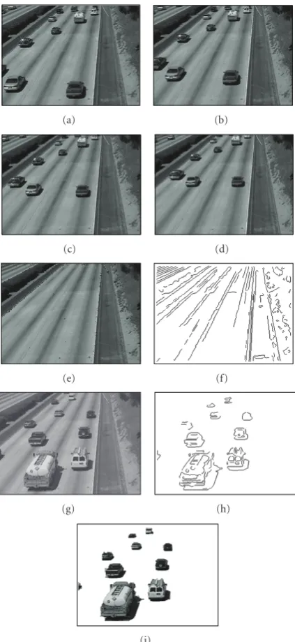
Figure 10 illustrates reference initialization and detec-tion of moving object in a busy road having complex back-ground. Figures 10(a)–10(d) show four samples of frames used for background initialization. Using previously men-tioned values for l and δmax (10 and 8, resp.), the
pro-posed method for background initialization successfully gen-erates the background, shown in Figure 10(e). Due to the slight movement of camera and cluttered scene, few num-bers of pixels did not obtain appropriate gray values. How-ever, as we utilize a set of images for reference initializa-tion, these noisy pixels do not have significant impact on the initial reference edge.Figure 10(f)depicts the resultant initial reference edges.Figure 10(g)shows the frame to de-tect moving object.Figure 10(h)displays the detected mov-ing edges, and correspondmov-ing movmov-ing objects are shown in
Figure 10(i).
Figure 11 shows that the proposed method is robust against slight movement of camera. Figure 11(a) shows a sample background image. Figures11(b)–11(d)show three consecutive frames (535–537) of a separate experiment. Frame 535, 536, and 537 have movement of 2, 3, and 4 pixels, respectively, with respect to the background along the up-per left direction. Thus each pair of consecutive frames has movement of 1 pixel.Figure 11(e)is the frame number 537 having similar movement of frame 535, manually adopted to illustrate different characteristic of the method proposed by Dailey et al. [10]. To demonstrate the robustness of the pro-posed method in camera movement, we compared it with the method proposed by Dailey et al. [10] and Kim and Hwang [8]. As mentioned inSection 2, to detect moving edge seg-ment of In, Dailey et al. utilize In−1 and In+1. Figure 11(f)
shows the result, obtained by the method proposed by Dai-ley et al. It is noticeable that many background edge pixels are detected as foreground edge pixels. Due to camera move-ment, background edge pixels of one frame cannot cancel out that of other frame. The result is even worse when previous (11.b) and next (11.e) frame has similar movement with re-spect to current frame. In this case, AND operation induces most of the background pixels in the detection result. This result is shown in Figure 11(g). The result obtained by the method proposed by Kim et al. is shown in Figure 11(h). Here Tstill and Tchange are set to 3. Due to camera
(a) (b) (c) (d)
(e) (f) (g) (h)
(i) (j) (k) (l)
(m) (n)
Ghost effect
(o) (p)
Figure9: Moving object detection and segmentation by the proposed method. (a) Frame 205; (b) edge image of detected moving object at frame 205; (c) segmented moving object of frame 205; (d) frame 290; (e) edge image of detected moving object at frame 290; (f) segmented moving object of frame 290; (g) edge image of updated reference edge at frame 322; (h) frame 419; (i) edge image of detected moving object at frame 419; (j) segmented moving object of frame 419; (k) frame 435; (l) edge image of detected moving object of frame 435; (m) segmented moving object of frame 435; (n) frame 470; (o) detected moving object of frame 470 with ghost effect; (p) segmented moving object of frame 470 using our proposed method.
edge segments. The result obtained by the proposed method is shown inFigure 11(i).λis set to 3 in this experiment.
The proposed method is robust against the change in il-lumination in a limited scale. Figures12(a)–12(f)illustrate some results of a separate experiment in indoor environment with illumination change. Figures12(a)and12(b)show the background and current frame, respectively, with different illuminations.Figure 12(c)shows the histogram of the dif-ference image. It is easily noticeable that there is no signifi-cant valley at the higher gray level region to detect the small moving object. However, for single thresholding, threshold
value exists at the valley of the two peaks (bimodal), or at the bottom rim of a single peak (unimodal) [27]. So, im-age differencing approaches followed by adaptive threshold-ing methods are not suitable for this situation.Figure 12(d)
(a) (b)
(c) (d)
(e) (f)
(g) (h)
(i)
Figure 10: Detection in complex background with more fore-grounds; (a)–(d) four intermediate images of a video sequence; (e) obtained background image; (f) edge image of the accumulated background; (g) current frame; (h) detected moving edges; (i) seg-mented moving objects.
background adapt with these variations. Moving edges ob-tained by the proposed method is shown in Figure 12(e).
Figure 12(f)shows the segmented moving object by the pro-posed method. Segmentation result for [8] is not included here as segmentation from moving edges to moving object is not presented in that paper. Figures12(g)–12(i)show the performance of the proposed method in outdoor environ-ment with illumination change.Figure 12(g)shows a sample of the background frame in bright state at noonused in refer-ence initialization.Figure 12(h)shows current frame in dark
(a) (b)
(c) (d)
(e) (f)
(g) (h)
(i)
Figure11: Results illustrating the performance in camera move-ment; (a) sample images of background; (b)–(d) frames 535, 536, and 537, respectively; (e) frame 537 having similar movement with frame 535; (f) result obtained by the method in [10] using frames in (b), (c), and (d); (g) result obtained by the method in [10] using frames in (b), (c), and (e); (h) result obtained by the method in [8]; (i) result obtained by the proposed method.
(a) (b)
(c) (d)
(e) (f)
(g) (h)
(i)
Figure 12: Results illustrating the performance in illumination change; (a) background frame. (b) frame 978 having different il-lumination; (c) histogram of difference image of (a) and (b); (d) edge image of detected moving object by the method of Kim et al.; (e) edge image of detected moving object by the proposed method; (f) segmented moving object by the proposed method; (g) back-ground of different experiment in bright state at noon; (h) cur-rent frame having moving object in dark state at afternoon. (i) seg-mented moving object.
Figure 13illustrates the segmentation result of the pro-posed method to comprehend its robustness even in the absence of some moving edge pixels in the detection result. A comparison between our segmentation result and the result obtained from VOP extraction method proposed by Kim et al. is also included. Kim et al. segment moving object region
(a) (b)
(c) (d)
(e) (f)
(g) (h)
(i) (j)
(k) (l)
by horizontal and vertical scanning followed by morpholog-ical operation. Figures 13(a)and13(b)illustrate the back-ground and current frame of a video sequence.Figure 13(c)
shows the detected moving edges by the method of Kim et al. Since extracted result has almost complete boundary of mov-ing object regions, Kim-Hwang’s VOP extraction method with the help of morphological closing extracts moving ob-ject region effectively. A 9×9 structuring element for mor-phological closing is utilized here. In such situation, our proposed method also works well to extract moving object regions. Results reflecting detected moving edges and seg-mented moving object by the proposed method are shown in Figures 13(e) and 13(f), respectively. However, due to the presence of low contrast between foreground and back-ground in the scene or in presence of illumination variation, moving edge detection result may be degraded. Figures13(g)
and13(h) show the background and current frame of an-other experiment where some portion of foreground and its neighboring background have almost similar gray scale val-ues and hence, low contrast persists. In this case, both meth-ods failed to detect complete boundary of moving objects. Moving edge detection result using methods of Kim et al. and the proposed one are shown in Figures13(i)and13(k), re-spectively. In this case, Kim-Hwang’s VOP extraction method fails to extract the moving object regions properly. Segmen-tation result using Kim-Hwang’s VOP extraction method is shown inFigure 13(j). Their method is largely dependent on the detected moving edges as well as the size of the structur-ing element. Figure 13(l)illustrates the moving object seg-mentation result obtained by the proposed method. Since, we have utilized watershed algorithm with the gradient in-formationGROIinstead of relying only on detected edge
in-formation, our proposed method segment out the moving object regions more accurately even in the presence of such challenging situation.
Table 1 shows the relative error rates in among three methods discussed in this paper. Here,τ,TM,TR,Tstill, and Tchange are set to 3, 16, 32, 3, and 3, respectively. Errors
are classified as false positive error (FPE) and false nega-tive error (FNE). FPE is the percentage of error due to de-tecting moving object in spite of no moving object exists in the scene. Similarly FNE is defined by the percentage of missing while moving object exists. However, indoor envi-ronment is more challenging than the outdoor in the case of moving object detection. This is due to the illumina-tion effect, which causes more variations in indoor scene. The proposed system generates more FPE than FNE. FPE occurs when comparatively large variation of illumination and reflection take place suddenly. The method proposed by Kim et al. also shows higher FPE than FNE. On the other hand, FNE is higher in the case of Dailey et al. This method misses detection of moving object when object moves very slowly. The rest two methods do not suffer from this prob-lem. Reduced error rate is recorded in experiment 2 due to the comparatively modest variations in environment during this experiment. However, overall error rate of the proposed method is less than 1%, which is acceptable considering the dynamism of real environment. Speed of the proposed method is reasonable as it processes 5 fps as compared to
Table1: Relative error rates in different environment.
Exp. no. Environment No. of Method FPE FNE
frames (%) (%)
1 Outdoor 2500
Proposed 0.45 0.09 Kim 1.56 0.16 Dailey 1.35 3.10
2 Outdoor 3000
Proposed 0.23 0.13 Kim 0.55 0.09 Dailey 0.33 2.05
3 Indoor 3000
Proposed 0.84 0.11 Kim 2.17 0.23 Dailey 1.79 3.35
2 fps by the method of Kim et al. and 7 fps by the method of Dailey et al.
5. CONCLUSIONS
The proposed system presents the effectiveness of the edge segment-based moving object segmentation method for au-tomated video surveillance. The shape information of seg-mented moving object can support the coding of video se-quences to allow separate and flexible reconstruction and manipulation at the decoder. Our goal is to design a dy-namic detection method that will be also robust in the case of moving object tracking and classifications. We designed edge class and matching procedure considering this goal. This pa-per illustrates the detection and segmentation parts of the proposed method, which proves its effectiveness by reduc-ing the risk of false alarm due to noise, change of illumina-tion, and contents of background while showing high sen-sitivity to the intruder. Numerous test results on real scenes and comparisons with some existing approaches justify the suitability of the proposed edge segment-based method for automated video surveillance. It also opens a new door to many related research issues including segment-based track-ing and motion analysis. We are currently pursutrack-ing tracktrack-ing and classification of the detected moving objects.
ACKNOWLEDGMENTS
The authors do like to mention their sincere thanks to Ahn Kiok, Assistant Manager, MG Systems Co. Ltd, South Korea, and Anwarul Hoque, System Engineer, AKTel, Bangladesh, for their continuous support and valuable suggestions during the implementation phase of the proposed system.
REFERENCES
[1] R. J. Radke, S. Andra, O. Al-Kofahi, and B. Roysam, “Image change detection algorithms: a systematic survey,”IEEE Trans-actions on Image Processing, vol. 14, no. 3, pp. 294–307, 2005. [2] A. Elgammal, R. Duraiswami, D. Harwood, and L. S. Davis,
[3] I. O. Sebe, J. Hu, S. You, and U. Neumann, “3D video surveil-lance with augmented virtual environments,” inProceedings of the 1st ACM SIGMM International Workshop on Video Surveil-lance (IWVS ’03), pp. 107–112, Berkeley, Calif, USA, Novem-ber 2003.
[4] M. Yokoyama and T. Poggio, “A contour-based moving ob-ject detection and tracking,” inProceedings of the 2nd Joint IEEE International Workshop on Visual Surveillance and Perfor-mance Evaluation of Tracking and Surveillance (VS-PETS ’05), pp. 271–276, Beijing, China, October 2005.
[5] M. J. Hossain, K. Ahn, J. H. Lee, and O. Chae, “Moving object detection in dynamic environment,” inProceedings of the 9th International Conference on Knowledge-Based Intelligent Infor-mation and Engineering Systems (KES ’05), vol. 3684 ofLecture Notes in Artificial Intelligence, pp. 359–365, Melbourne, Aus-tralia, September 2005.
[6] P. L. Rosin, “Edges: saliency measures and automatic thresh-olding,” Machine Vision and Applications, vol. 9, no. 4, pp. 139–159, 1997.
[7] J. H. Duncan and T.-C. Chou, “On the detection of motion and the computation of optical flow,”IEEE Transactions on Pattern Analysis and Machine Intelligence, vol. 14, no. 3, pp. 346–352, 1992.
[8] C. Kim and J.-N. Hwang, “Fast and automatic video object segmentation and tracking for content-based applications,” IEEE Transactions on Circuits and Systems for Video Technol-ogy, vol. 12, no. 2, pp. 122–129, 2002.
[9] A. D. Sappa and F. Dornaika, “An edge-based approach to mo-tion detecmo-tion,” inProceedings of the 6th International Confer-ence on Computational SciConfer-ence (ICCS ’06), vol. 3991, part 1 of LNCS, pp. 563–570, Reading, UK, May 2006.
[10] D. J. Dailey, F. W. Cathey, and S. Pumrin, “An algorithm to estimate mean traffic speed using uncalibrated cameras,”IEEE Transactions on Intelligent Transportation Systems, vol. 1, no. 2, pp. 98–107, 2000.
[11] K. Ahn, H. J. Hwang, and O. Chae, “Design and implemen-tation of edge class for Image analysis algorithm development based on standard edge,” inProceedings of the 30th Interna-tional KISS Autumn Conference, pp. 589–591, Korea, 2003. [12] Y. Ahn, K. Ahn, and O. Chae, “Detection of moving
ob-jects edges to implement home security system in a wireless environment,” inProceedings of the International Conference on Computational Science and Its Applications (ICCSA ’04), vol. 3043, part 1, pp. 1044–1051, Springer, Assisi, Italy, May 2004.
[13] A. Makarov, J.-M. Vesin, and M. Kunt, “Intrusion detec-tion using extracdetec-tion of moving edges,” inProceedings of the 12th IAPR International Conference on Pattern Recognition— Conference A: Computer Vision & Image Processing (ICPR ’94), vol. 1, pp. 804–807, Jerusalem, Israel, October 1994.
[14] P. L. Rosin, “Thresholding for change detection,”Computer Vi-sion and Image Understanding, vol. 86, no. 2, pp. 79–95, 2002. [15] R. Jain and H.-H. Nagel, “On the analysis of accumulative dif-ference pictures from image sequences of real world scenes,” IEEE Transactions on Pattern Analysis and Machine Intelligence, vol. 1, no. 2, pp. 206–214, 1979.
[16] Y. Z. Hsu, H.-H. Nagel, and G. Rekers, “New likelihood test methods for change detection in image sequences,”Computer Vision, Graphics, and Image Processing, vol. 26, no. 1, pp. 73– 106, 1984.
[17] A. Cavallaro, E. Salvador, and T. Ebrahimi, “Shadow-aware object-based video processing,”IEE Proceedings—Vision, Im-age and Signal Processing, vol. 152, no. 4, pp. 398–406, 2005.
[18] J. L. Barron, D. J. Fleet, and S. S. Beauchemin, “Performance of optical flow techniques,”International Journal of Computer Vision, vol. 12, no. 1, pp. 43–77, 1994.
[19] M. J. Hossain, M. A. A. Dewan, and O. Chae, “Moving object detection for real time video surveillance: an edge based ap-proach,”IEICE Transactions on Communications, vol. E90-B, no. 12, pp. 3654–3664, 2007.
[20] J. Canny, “A computational approach to edge detection,” IEEE Transactions on Pattern Analysis and Machine Intelligence, vol. 8, no. 6, pp. 679–698, 1986.
[21] S. M. Smith and J. M. Brady, “SUSAN—a new approach to low level image processing,”International Journal of Computer Vision, vol. 23, no. 1, pp. 45–78, 1997.
[22] H.-C. Liu and M. D. Srinath, “Partial shape classification using contour matching in distance transformation,”IEEE Trans-actions on Pattern Analysis and Machine Intelligence, vol. 12, no. 11, pp. 1072–1079, 1990.
[23] G. Borgefors, “Hierarchical chamfer matching: a parametric edge matching algorithm,”IEEE Transactions on Pattern Anal-ysis and Machine Intelligence, vol. 10, no. 6, pp. 849–865, 1988. [24] D. Gutchess, M. Trajkovi´c, E. Cohen-Solal, D. Lyons, and A. K. Jain, “A background model initialization algorithm for video surveillance,” inProceedings of the 8th International Conference on Computer Vision (ICCV ’01), vol. 1, pp. 733–740, Vancou-ver, BC, Canada, July 2001.
[25] J. H. Lee, Y. T. Cho, H. Heo, and O. Chae, “MTES: visual programming environment for teaching and research in im-age processing,” inProceedings of the 5th International Confer-ence on Computational SciConfer-ence (ICCS ’05), vol. 3514, part 1 of LNCS, pp. 1035–1042, Springer, Atlanta, GA, USA, May 2005. [26] R. Cucchiara, C. Grana, M. Piccardi, and A. Prati, “Detect-ing mov“Detect-ing objects, ghosts, and shadows in video streams,” IEEE Transactions on Pattern Analysis and Machine Intelligence, vol. 25, no. 10, pp. 1337–1342, 2003.
[27] A. Mecocci, “Moving object recognition and classification in external environments,”Signal Processing, vol. 18, no. 2, pp. 183–194, 1989.
[28] N. Otsu, “Threshold selection method from gray-level his-tograms,”IEEE Transcations on Systems, Man, and Cybernetics, vol. 9, no. 1, pp. 62–66, 1979.
[29] L. Vincent and P. Soille, “Watersheds in digital spaces: an effi -cient algorithm based on immersion simulations,”IEEE Trans-actions on Pattern Analysis and Machine Intelligence, vol. 13, no. 6, pp. 583–598, 1991.
[30] M. A. Hoque, “Reliable marker generation method based on boundary information,” MS dissertation, Computer Engineer-ing Department, Kyung Hee University, Seoul, Korea, 2006. [31] F. Meyer, “Topographic distance and watershed lines,”Signal
Processing, vol. 38, no. 1, pp. 113–125, 1994.