Ceramic MFCs with internal cathode producing sufficient power for practical applications
Iwona Gajdaa*, Andrew Stinchcombea, John Greenmana,b, Chris Melhuisha, Ioannis Ieropoulosa,b*
aBristol BioEnergy Centre, Bristol Robotics Laboratory, University of the West of England,
BS16 1QY, UK
bBiological, Biomedical and Analytical Sciences, University of the West of England, BS16
1QY, UK
* Corresponding author: Bristol BioEnergy Centre,Bristol Robotics Laboratory, T-Building, UWE, Frenchay Campus, Bristol, BS16 1QY, UK
E-mail address: [email protected] (I. Ieropoulos)Tel.: +44 117 32 86318, 86322; Fax: +44 117 32 83960
E-mail address: [email protected] (I. Gajda) Tel.:+44 117 32 82395
Highlights
- Ceramic MFCs with inner cathode chamber show good performance to power practical applications
- Three MFC units connected in parallel could energise directly a DC motor continuously for over 6 days
- During MFC operation accumulation of catholyte improves performance
- A single MFC was shown to charge a mobile phone with the aid of energy harvesting electronics
- Inverted design shows the potential for MFCs to be directly immersed in wastewater extracting caustic catholyte
Abstract
This communication reports on the powering of real world applications, whereby three interconnected MFCs directly power an external DC motor, and a single MFC recharges a mobile phone, via energy harvesting. The work is aiming to evaluate MFC performance based on low-cost, catalyst-free conditions, with an internal cathode to operate practical applications. It presents the case for simple and easy-to-operate ceramic-based designs as a viable approach to larger-scale implementation in real-world conditions such as wastewater treatment plants. MFCs hold great promise for sustainable wastewater treatment since they are the only technology that directly generates electricity from the break-down of waste. 1
Key words: Microbial Fuel Cell (MFC), off the grid energy, wastewater treatment, activated carbon, internal cathode
1. Introduction
Providing adequate sanitation and clean water to a global population is today’s economic challenge. Microbial fuel cells (MFCs) offer potential for direct biological conversion of wastewater organic materials directly into electricity [1]. Significant improvements in power performance have been achieved in the last 2 decades, so the successful, commercial real-life MFC demonstration is closer than ever before. Recent advances in various fundamental areas can lead to practical applications [2] and subsequently to commercial use. Substantial
progress has been made towards enabling the implementation of this technology by replacing expensive components such as platinum electrodes with carbon, membranes with ceramics [3,4] simplifying operational conditions [5] and modifying reactor designs [6]. In recent review the designoptimisation, improved harvesting and cost reduction have been identified as main areas that require improvement towards the generation of practically usable power [7]. A better understanding of the impact of reactor components on the performance of the reaction system is an important step towards commercialisation of Bioelectrochemical Systems (BES) [8,9].The major hurdles are being recognised in design and engineering rather than biology [10]. Understanding these phenomena can allow us to identify ways of optimising reactor design, process conditions, and optimal outputs. The attempts to
implement the MFC technology into wastewater treatment plants have thus far been limited by relatively low power densities, however, in recent study MFC was powering a pump intermittently in the aerated lagoon treatment system improving organics removal [11]. At the same time, attempts of scaling up have investigated various approaches such as a plate [12], cassette [10] or tubular systems [13–15]. In general, the multiplication and miniaturisation offers an alternative way of scaling up [16] that could be used to power mobile robots [17], due to increased power density of miniaturised MFC units [18]. In this respect, a stack of tubular MFCs provides a method of obtaining high surface areas in standard (inner anode, outside cathode) configurations and it has shown to power a commercial mobile phone handset [19]. This work is aiming to present the inverted configuration where the anode is placed outside and the cathode inside the tube to emphasise the practicality of the internal cathode design in the MFC. In this way, the proposed simple and cost effective design can be used as a functional unit by directly immersing it in wastewater tanks. With a reversed electrode set up, this work is leading further into simultaneous water recovery in the form of 35
catholyte [20] that could be collected from the internal cathode chamber, which is the reason why the energy-rich organic waste streams can be used as a high value fuel, increasing energy recovery. This work also aims to present the essential component of catholyte accumulation (known in chemical fuel cells as “flooding”) inside the cathode chamber improving - instead of hindering - the performance. This work also aims to demonstrate the practical use of these MFCs, by (i) driving a motorised model windmill directly using 3 MFCs connected together and (ii) charging a mobile phone via energy harvesting electronics using a single MFC.
2. Experimental
MFCs were assembled using 10 cm long, 3 mm wall thickness terracotta caves (Orwell Aquatics, UK) serving both as the MFC casing and a separator between the anode and the cathode. Anode electrodes were 2430 cm2; 20 gsm carbon fibre veil (PRF Composites, UK) wrapped around the ceramic cave and pressed against the wall with nickel chromium wire (0.45 mm diameter). Cathode electrodes were made of activated carbon and PTFE paste applied on the same carbon fibre veil substratum (90 cm2; 20 gsm) as previously described [21] and placed inside the cylinder so the activated carbon was facing the ceramic wall. A stainless steel crocodile clip and Ni-Chr wire was used for connecting the cathodes. The terracotta MFCs were placed inside plastic containers, inoculated with 200 mL of activated sludge provided by Wessex Water Scientific Laboratory (Cam Valley, Saltford, UK) and operated in batch conditions to assess its performance and catholyte accumulation. The anolyte was periodically supplemented with a mixture of activated sludge and 20 mM sodium acetate at pH 6.7 - 7.9. A total of three MFCs (units labelled as T1-T3) were tested under an external resistor load of 53 Ω and a further 3 MFCs were tested under open circuit conditions (units labelled as T4-T6). All tests were performed under room temperature, 22 ºC, without pH control or any platinum catalyst.
A model windmill equipped with a DC electric motor (RF-300CA-11440 DC/2.0V 11303 , HSC Motors) was used as practical demonstrator of the usable power from the three parallel connected MFCs. A 300F 2.7 V max. super-capacitor (XW3550/2R7307/R, Cooper
Bussmann) was also used to store excess energy in addition to powering the windmill.
Furthermore, a mobile phone Samsung GT-E2121B was connected via a Texas Instruments energy harvester (TI BQ25504EVM-674, Farnell, UK). The output voltage from the single ceramic MFC was insufficient to meet the voltage requirements of the phone battery and 68
charge it directly, hence the energy harvester was used. Data logging was performed via multichannel DAQ Agilent 34972A (Farnell, UK). Current and power output levels were calculated as previously described [18].
3. Results and Discussion 3.1. Performance
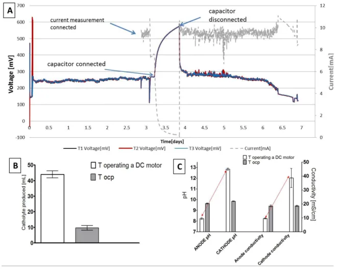
Tubular MFCs were tested in closed circuit conditions, under 53 Ω external resistor (T1, T2, T3) and open circuit conditions (T4, T5, T6). A stable power output was recorded over a period of 7 days with an average of 805 µW, 458 µW and 880 µW, for T1, T2 and T3 respectively, whilst the open circuit MFCs produced open circuit voltages of T4 649 mV, T5 638 mV and T6 656 mV. To demonstrate the useful power levels of the tested units, T1, T2 and T3 had their external resistors removed and connected in parallel directly to power the windmill motor. The substrate was replenished by fresh sludge+20 mM sodium acetate at pH 7.9 and conductivity of 17.7 mS/cm. Figure 1 illustrates the energising of the windmill DC motor. As can be seen, the voltage output was steadily increasing over a period of 3 days, from 245 mV to 265 mV, after which period a current probe was connected to measure the current directly, which was shown to be approximately 9.6 mA throughout. The test also included connecting a 300F super-capacitor to the circuit, whist the motor was still running, showing excess amounts of electricity that could be stored in a system during continuous operation. This shows that the additional energy stored in the capacitor would make the system more efficient. At the end of the 6th day, the motor stopped when the voltage level dropped below 200mV. It was observed that during this practical demonstration catholyte was produced and accumulated in the internal cathode chamber. On average, as shown in Figure 1B, MFCs powering an external circuit generated 44 mL of catholyte whilst the open circuit MFCs produced only 9.6 mL, which is significantly less volume. This suggests that some passive diffusion through the terracotta material was occurring primarily for the open-circuit MFCs, but when under load, anolyte was transported via electro-osmostic drag [13]. Catholyte properties include a significantly higher pH and an almost two-fold increase in conductivity values in comparison with the catholyte formed from the open circuit MFCs. This might be one reason why MFC operation was improved [22]. Similar caustic catholyte formation in MFC has been previously reported [20] and this could be one method of
recycling wastewater and generating caustic solutions. (See Supplementary Information for a video clip of the windmill running with only 1 MFC).
Figure 1.A- T1, T2 and T3 connected in parallel continuous operation of the DC motor operating a model windmill; B- Amount of the catholyte collected after a 7 day continuous operation; C-pH and conductivity under open and closed circuit conditions.
3.2. Catholyte effect
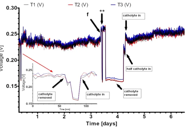
To explore the effect of the accumulated catholyte on the MFC performance, the catholyte was removed from all 3 working MFCs (T1, T2 and T3; Figure 2 inset), whilst connected and running the windmill. During this process, when the whole catholyte was removed, the motor stopped working, and only started again when the catholyte was reinstated in the inner cathode chamber. This was repeated as marked by the (**) on the Figure 2, after feeding the MFCs with fresh feedstock (f). As before, the motor stopped when the cathode chamber was emptied and started working normally when the same catholyte was returned into the
cathode. This procedure was repeated a third time, leaving the cathode empty for a day, during which the windmill had once again stopped working. After this period, only half of the catholyte was reinstated into the cathode, which resulted in a slower windmill operation – see Table 1. When the full catholyte volume was added back into the cathode, the MFC
performance once again stabilised and the windmill reached full speed and continued for the next three days. Catholyte provides a moisture bridge and sufficient hydration for the oxygen reduction reaction (ORR). In previous work, ceramic MFCs with the cathode outside,
demonstrated improved performance following manual hydration and in addition showed higher rates of anolyte dissipation when the cathode was intentionally not supplied with water [4]. In a further previous study, where inner cathodes were tested, forced air flow through the cathode tube was shown to decrease power generation, therefore it can be assumed that the cathode in such a configuration could be drying out [5].
Figure 2. Effect of accumulated catholyte during MFCs powering a motor, “f”-feeding with fresh feedstock, **-repeated catholyte removal resulting in the same behaviour as shown in the inset. Table 1. Detailed performance of the stack powering the dc motor as shown in Figure 2.
Catholyte average [mL] Voltage [mV] Motor performance [rpm]
day 0 cathode emptied 0 164 0
day 0 catholyte put back in 16.6 238 88
day 3 before feeding 53 246 108
day 3 after feeding 53 260 144
day 3 cathode emptied 0 167 0
day 4 half of the catholyte in 26.5 226 96
148 149 150 151 152 153 154 155
day 4 whole catholyte in 53 243 132
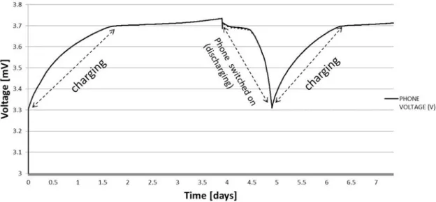
Figure 3 shows the single tubular MFC as a power source for charging a mobile phone, using an energy harvesting system. Previously it has been demonstrated this could be done directly via a stack of 12 MFCs [19], here the inverted configuration (cathode inside) of one single MFC enabled charging through smart electronics.
Figure 3. Charging cycles of the commercial mobile phone via single MFC and an energy harvesting system.
The current study also demonstrates that the capital cost of the system could be substantially reduced through system designs that use less expensive electrodes (carbon veil cost is only £6.70/m2), ceramic membranes and simple design for optimised operation. A recent report showed that in clayware cylinders (inner anode, outer cathode) with multiple electrodes exposed to the same liquid, maximum power can be extracted using parallel circuit
connection [14]. Therefore, the MFCs operated as individual units in the present study, would perform equally well when immersed in one common feedstock tank but kept in parallel as recently demonstrated at theReinvent the Toilet Fair in Delhi, India, in March 2014 under the the Bill & Melinda Gates Foundation [23] or indeed when kept in fluidic-electrical isolation as part of a cascade stack designed to treat the same feedstock [24]. This study is contributing new knowledge in the area of MFC based wastewater treatment, but further research is still required for MFC stacks in this application scenario, especially when the level of energy output (i.e. driving a real world device such as a pump) becomes the governing factor of treatment efficiency and catholyte recovery.
161 162 163 164 165
Conclusions
Microbial Fuel Cell which is representing a bioconversion technology, serves as a standalone power source for practical applications. This work is presenting ready to implement MFCs by simply immersing the units directly in the wastewater. The development of ready to use MFCs in different stages of real wastewater treatment plants would help to lower the consumption of energy for wastewater treatment and consequently establish a more stable energy network.
Acknowledgements
This work was funded by the Engineering and Physical Sciences Research Council – United Kingdom EPSRC CAF EP-I004653/1 and EP/L002132/1. Parts of this study have contributed to the Urine-tricity++ project, funded by the Bill & Melinda Gates Foundation, grant no. OPP1094890.
References
[1] Allen RM, Bennetto HP. Microbial fuel-cells. Appl Biochem Biotechnol 1993;39-40:27–40.
[2] Torres CI. On the importance of identifying, characterizing, and predicting
fundamental phenomena towards microbial electrochemistry applications. Curr Opin Biotechnol 2014;27:107–14.
[3] Behera M, Jana PS, Ghangrekar MM. Performance evaluation of low cost microbial fuel cell fabricated using earthen pot with biotic and abiotic cathode. Bioresour Technol 2010;101:1183–9.
[4] Winfield J, Greenman J, Huson D, Ieropoulos I. Comparing terracotta and earthenware for multiple functionalities in microbial fuel cells. Bioprocess Biosyst Eng
2013;36:1913–21.
[5] Liu H, Ramnarayanan R, Logan BE. Production of electricity during wastewater treatment using a single chamber microbial fuel cell. Environ Sci Technol 2004;38:2281–5.
[6] Papaharalabos G, Greenman J, Melhuish C, Ieropoulos I. A novel small scale Microbial Fuel Cell design for increased electricity generation and waste water treatment. Int J Hydrogen Energy 2015;40:4263–8.
[7] Wang H, Park J, Ren ZJ. Practical Energy Harvesting for Microbial Fuel Cells: A Review. Environ Sci Technol 2015;49:3267–77.
[8] Krieg T, Sydow A, Schröder U, Schrader J, Holtmann D. Reactor concepts for
bioelectrochemical syntheses and energy conversion. Trends Biotechnol 2014;32:645– 55.
[9] Pant D, Singh A, Van Bogaert G, Gallego YA, Diels L, Vanbroekhoven K. An introduction to the life cycle assessment (LCA) of bioelectrochemical systems (BES) for sustainable energy and product generation: Relevance and key aspects. Renew Sustain Energy Rev 2011;15:1305–13.
[10] Heidrich ES, Edwards SR, Dolfing J, Cotterill SE, Curtis TP. Performance of a pilot scale microbial electrolysis cell fed on domestic wastewater at ambient temperatures for a 12 month period. Bioresour Technol 2014;173:87–95.
[11] Ewing T, Babauta JT, Atci E, Tang N, Orellana J, Heo D, et al. Self-powered wastewater treatment for the enhanced operation of a facultative lagoon. J Power Sources 2014.
[12] Aelterman P, Rabaey K, The Pham H, Boon N, Verstraete W. Continuous electricity generation at high voltages and currents using stacked microbial fuel cells. Commun Agric Appl Biol Sci 2006;71:63–6.
[13] Kim JR, Premier GC, Hawkes FR, Dinsdale RM, Guwy AJ. Development of a tubular microbial fuel cell (MFC) employing a membrane electrode assembly cathode. J Power Sources 2009;187:393–9.
[14] Ghadge AN, Ghangrekar MM. Performance of low cost scalable air-cathode microbial fuel cell made from clayware separator using multiple electrodes. Bioresour Technol 2015.
[15] Zhang L, Li J, Zhu X, Ye D, Liao Q. Effect of proton transfer on the performance of unbuffered tubular microbial fuel cells in continuous flow mode. Int J Hydrogen Energy 2015;40:3953–60.
[16] Ieropoulos I, Greenman J, Melhuish C. Improved energy output levels from small-scale Microbial Fuel Cells. Bioelectrochemistry 2010;78:44–50.
[17] Ieropoulos I, Greenman J, Melhuish C. Imitating metabolism: Energy autonomy in biologically inspired robots. Proc. AISB, 2003, p. 1–4.
[18] Ieropoulos I, Greenman J, Melhuish C. Microbial fuel cells based on carbon veil electrodes: Stack configuration and scalability. Int J Energy Res 2008;32:1228–40.
[19] Ieropoulos I, Ledezma P, Stinchcombe A, Papaharalabos G, Melhuish C, Greenman J. Waste to real energy: the first MFC powered mobile phone. Phys Chem Chem Phys 2013;15:15312–6.
[20] Gajda I, Greenman J, Melhuish C, Santoro C, Li B, Cristiani P, et al. Water formation at the cathode and sodium recovery using Microbial Fuel Cells (MFCs). Sustain Energy Technol Assessments 2014;7:187–94.
[21] Gajda I, Greenman J, Melhuish C, Ieropoulos I. Simultaneous electricity generation and microbially-assisted electrosynthesis in ceramic MFCs. Bioelectrochemistry 2015;104:58–64.
[22] Ahn Y, Logan BE. Saline catholytes as alternatives to phosphate buffers in microbial fuel cells. Bioresour Technol 2013;132:436–9.
[23] Gatesfoundation.org. Urine-tricity. Reinvent-the-Toilet-Fair-India-2014-Program 2014:Page 13.
[24] Winfield J, Ieropoulos I, Greenman J. Investigating a cascade of seven hydraulically connected microbial fuel cells. Bioresour Technol 2012;110:245–50.