For Service Manuals MAURITRON SERVICES 8 Cherry Tree Road, Chlnnor
Oxfordshire, OX9 4Qy'
Tel (01844) 351694 Fax (01844) 352554
email:·[email protected]
I
I
I
i ; i ,
! , I
I
I1
I
I
I
, : I iI i , I
j I
I
j1
I
I
1 I II
I I 1 I I II
I II
I
I
t· "ij
l
-1",li~
}
ti
~
I
~:,
.~
1
)
%1\
;e, ~)
I
rI
I
III
!
I
i
I
II
I
l,I
1 :~,~OVERVIEW
This maintenance manual contains information on how to service
and repair the WY-30 terminal. We assume you are a qualified
service technician with previous experience in terminal and
computer repair. To take full advantage of this manual, we
suggest you read the information in the order presented.
HOW TO USE THIS MANUAL
This manual is divided into seven chapters and four appendixes. Chapter one provides important information for the technician who
has never serviced this terminal before. If you are already
familiar with the terminal, the technical information in Appendix A can remind you about the terminal.
Here is a summary of this manual:
Chapter 1, "General Information," describes the terminal, including information about internal functions, input/output (I/O), telecommunications, environmental needs, and operator controls.
Chapter 2, "Removal and Replacement Procedures," shows you how to take the terminal apart and put i t back together again.
Chapter
3,
"Troubleshooting," tellsto fix problems with the terminal. needed for troubleshooting, a quick flowchart.
you what to look for and how It includes a list of tools
reference guide, and a
Chapter
4,
"Adjustments and Alignments," describes power supplyand monitor adjustments that control the quality of the display.
Chapter 5, "Illustrated Parts List," includes a list of display and keyboard assembly parts.
Chapter 6, "Theory of Operation," describes the terminal
operation by function.
Chapter
7,
"Schematics," contains schematic representations ofAppendix A, "Specifications," lists the terminal's specifications.
Appendix B, "Connector Pin Assignments," lists the signals on each pin of the MODEM and the AUX ports located on the rear panel of the terminal.
Appendix C, "Test Connectors," describes how to make diagnostic hood test connectors.
Appendix D, "Display Inspection With the Reticle," describes how
to check the terminal's display with a special tool, the reticle.
REFERENCE MANUALS
The following publications provide additional information about the termina l:
WY-30 User's Guide, Document 880093-01
TABLE OF CONTENTS
OVERVIEW
...
i i iGENERAL INFORMATION
Introduction . . . 1-2 High Level Functional Description . . . 1-2 Microcomputer . . . 1-2
Memory . . . 1-2
Terminal Control . . . 1-2 Input/Output Devices . . . 1-2 Environment . . . 1-4 Operator Interfaces . . . 1-5
Setup Parameters . . . 1-6
Cleaning . . . 1-7
2 REMOVAL AND REPLACEMENT PROCEDURES
Overview . . . 2-2 Before You Start . . . 2-2 Removing and Replacing Assemblies in the
Keyboard Mod ule . . . 2-3
Removing and Replacing Assemblies in the
Terminal Module . . . 2-5
3 TROUBLESHOOTING
Before You Start . . . 3-2
Troubleshooting Quick Reference Guide . . . 3-3
Troubleshooting Flowchart . . . 3-3
Troubleshooting Aids . . . 3-8
4 ADJUSTMENTS AND ALIGNMENTS
Before You Start . . . 4-2 Power Adjustments . . . 4-3
5 ILLUSTRATED PARTS LIST
Introduction . . . • . . . . • . . . 5-2
Terminal Display Assembly Exploded View . . . 5-3
Keyboard Assembly Exploded View . . . 5-4 Terminal Components List . . . • • • . . . • . . • . . . • . 5-5 Keyboard Components List . . . • . . . • . . . 5-8 Terminal Board Assembly Layout . • . . . . • . . . • . . • . . . . • . . . • . . . 5-9
6 THEORY OF OPERATION
Introduction • . . . • . . . • . . . 6-2 Microcomputer and Related Logic . . . 6-2 Power Supply and Monitor Circuitry . . . 6-10 Keyboard . . • . . . • . . . • • . . . 6-13 Communication Ports . . . 6-13 Terms and Abbreviations . . • . . • • . • . . . • . . . · · · • · · · · 6-13
7 SCHEMATICS
Keyboard PCB . . . • . . . · · · 7-3 Term i na 1 PCB (L 0 g i c) . . . • . . . . • • . . • • . • . . . • • . . . 7 - 5
Terminal PCB (Monitor/Power Supply) . . . 7-7
APPENDIXES
A Specifications . . . • . . . ··· A-1 B Connector Pin Assignments . . . • . . . . • . . . • • . . . B-1 C Test Connectors . . . • . . . C-1
D Display Inspection with the Reticle . . . D-1
INDEX . . . 1-1
LIST OF FIGURES
LIST OF FIGURES Continued
4-1 Power Supply Component Layout . . . 4-3 4-2 Ad j us tmen t Locations . . . 4-8 4-3 Yoke Lock on the CRT Neck . . . 4-10 4-4 Display Magnets . . . ~ . . . 4-11 4-5 Centering Rings . . . 4-12 5-1 Terminal Display Assembly Exploded View . . . 5-3 5-2 Keyboard Assembly Exploded View . . . 5-4 5-3 Terminal Board Assembly Layout . . . 5-9 6-1 Memory Map . . . 6-3 7-1 Keyboard PCB Schematic . . . 7-3 7-2 Terminal PCB Schematic (Logic) . . . 7-5 7-3 Terminal PCB Schematic (Monitor/Power Supply) . . . 7-7 D-1 Video Inspection Reticle . . . D-1 D-2 Checking Width and Height . . . D-3 D-3 Checking Straightness, Pincushioning,
Centering, and Vertical Linearity . . . D-4
LIST OF TABLES
3-1 Troubleshooting Quick Reference Guide . . . 3-3 3-2 Terminal Installation Checklist . . . 3-8 3-3 Power-On Self-Test Error Messages . . . 3-11 3-4 Diagnostic Self-Test Error Messages . . . 3-12
1 GENERAL INFORMATION
Introduction
...
1-2High Level Functional Description . . . 1-2
Microcomputer . . . 1-2
Memory . . . 1-2
Terminal Control . . . 1-2
Input/Output Devices . . . 1-2 CRT Display . . . 1-3
Communications Interfaces . . . 1-3
Keyboard . . . 1-3
Environment
...
1-4Operator Interfaces . . . 1-5
Keyboard . . . 1-5
P ower Cord . . . 1-6
Communications Cable . . . 1-6
AC Power Switch . . . 1-6
Brigh tness Slideswi tch . . . 1-6
Touch/Tilt Screen Adjustment . . . 1-6
Setup Parameters . . . 1-6
INTRODUCTION
The WY-30 is a low-cost, entry-level, ASCII display terminal. It consists of a display console and a detachable keyboard. A user enters information for display from the keyboard. The terminal contains all of the electronics that support the display and keyboard.
In addition to the cathode ray tube (CRT) and keyboard, the WY-30 contains two independent communications interfaces. Peripherals, including a hard-copy printer or plotter, can be attached to the terminal with interface connectors on the rear panel.
The component parts are organized around and controlled by the microprocessor. The microprocessor controls all internal data manipulation and processing functions.
HIGH LEVEL FUNCTIONAL DESCRIPTION
The terminal consists of a microprocessor and related logic, a CRT controller and associated control logic, input/output (I/O) devices, monitor and power supply circuitry, and a CRT. All
circuitry is mounted on a single printed circuit board (PCB), the terminal PCB. The microprocessor controls all basic functions.
MICROCOMPUTER
The microcomputer comprises a clock and synchronization circuit, program memory, 4K of RAM, a reset circuit, and the heart of the terminal--a 2-megahertz, 6800-family microprocessor--the 68BOO.
MEMORY
Terminal memory consists of RAM and ROM. The microprocessor uses 4K of RAM for buffers, variable storage and system stack. The video interface shares this RAM for screen refresh. Program memory, 8K of ROM, holds all the terminal control firmware.
TERMINAL CONTROL
Functions of the terminal control firmware include keyboard scanning, video control, data transfer to and from the
communication ports, and on-screen data manipulation.
INPUT/OUTPUT DEVICES
CRT Display
The terminal has a 14-inch, flat-screen CRT. It displays 24 rows of characters, SO columns, and two control rows (one for terminal status and the other for label, message, and setup). The CRT -controller reads displayed characters from RAM on a direct memory access (DMA) basis.
Communications Interfaces
The terminal has two asynchronous serial interfaces that conform with the EIA standard RS-232C. Data rates are set for both
interfaces together. These parameters are operator controlled and are defined in "Setup Parameters" in this chapter. Both interfaces can communicate at data rates up to 3S.4K bits per second (bps).
Keyboard
The keyboard consists of 83 keys mounted on a single-sided PCB. All keys are momentary action key switches. The microprocessor periodically scans the keys checking for key closures.
Figure 1-1 shows the keyboard. You can find a detailed description in Chapter 6, "Theory of Operations."
Figure 1-1 Keyboard
F5 ! 1=6 F7 F8 Ins Char Del Char Clr Line Replae· inS Line Del. l,ne ell Page Insert
~~~~ P3ge Copy PM :~: ~E
[][][][][][][][][][][]O[]
BackSpaceLJ
[][]CJ[
LJ~~D~OD~~~~D~D~ ~~~[
DEJ[][J[]EJrJtJr:JODDI
ReturnIe:]
[][]~[
EJLJDDD[][][]E][][][[]LJLJu
D[][][n ..
ENVIRONMENT
The terminal can be placed on a table, desktop, or any other vibration-free horizontal surface that is free from lint and dust. Abnormally bright room light or direct sunlight can interfere with the display."
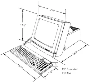
Figure 1-2 shows the WY-30 dimensions. The user should allow three inches of clearance on all sides when installing the terminal.
Users can install the terminal near most other types of electrical or electronic equipment without serious interference. They should avoid locations near strong magnetic fields that can distort and interfere with the operating or servicing of the video display.
Figure 1-2 Terminal Dimensions
2'14" Extended
1 '12" Flat
..
,.:'"
OPERATOR INTERFACES
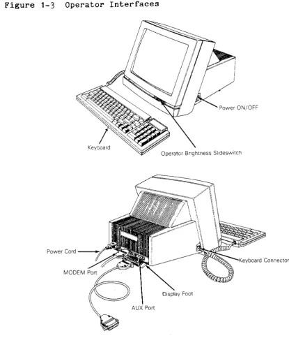
Figure 1-3 shows all operator interfaces, including the keyboard, power cord, and brightness slideswitch. It also points out the MODEM and AUX ports.
Figure 1-3 Operator Interfaces
Power ON/OFF
Power Cord
Insert the power cord into the connection on the rear panel, and then plug the three-pronged connector into the AC power source.
Caution--Compare the voltage specified on the configuration label (on the back of the CRT enclosure) with the AC power source to avoid damaging the terminal.
Communications Cable
Connect the communications cable from the computer or modem to the communications port labeled MODEM. This port defaults at 9600 baud, no parity, with one stop bit and eight data bits. The operator can change these parameters in setup mode.
AC Power Switch
The power switch is on the right side of the terminal. Pressing the back of the switch turns AC power on.
Brightness Slideswitch
The brightness slideswitch is located on the lower-right corner of the front bezel. Sliding the switch to the right increases the display brightness; sliding it to the left decreases the brightness.
Touch/Tilt Screen Adjustment
The touch/tilt screen adjustment is a spring-controlled support flap on the bottom of the terminal enclosure. A user can adjust the angle at which he views the screen by pushing or pulling the terminal bezel.
SETUP PARAMETERS
When a user turns the power on, the terminal executes an internal self-test. When the self-test finishes and the CRT is warm
(approximately 30 seconds), the cursor appears in the upper left-hand corner of the display. The unit is now ready for operation based on the setup parameters.
To change the parameters, follow these steps:
1. Enter setup mode by pressing the SHIFT and SETUP keys.
2. Press CURSOR DOWN until the parameter to be changed is displayed in the setup line, the row of highlighted fields at the bottom row of the screen.
3. Press CURSOR RIGHT or LEFT until the specific parameter to be changed is highlighted.
4. Press the spacebar to advance the parameter to the specific setting desired.
5. Press the cursor keys as required to advance to the next parameter to be changed.
6. To leave setup mode, press the SHIFT and SETUP keys.
The status line flashes a message asking if the changed parameters should be saved for power-on. Parameter changes are implemented immediately.
Pressing the Y key saves the parameters that you keyed in.
Pressing the N key saves all changes temporarily. The new parameters are effective only until you turn off the power.
Pressing the ESC key returns all parameters to their factory default values.
Pressing the ENTER key restores all parameters from memory before leaving setup mode.
7.
To return to a normal operation mode, press any key.The terminal is now operational using the parameters defined in the setup mode.
See the WY-30 User's Guide for more comprehensive setup instructions.
CLEANING
2 REMOVAL AND REPLACEMENT PROCEDURES
Overview
...
2-2Before You Start . . . 2-2 Safety . . . 2-2
Required Tools . . . 2-3
Removing and Replacing Assemblies in the
Keyboard Module . . . 2-3
Keyboard ....•.••.••• ;:, • • • • . • • • . • . • • . • . . . • • . • • • • • • • • . . • . . . 2-3
Keyboard Cable . . . 2-4
Keyboard PCB . . . 2-5
Removing and Replacing Assemblies in the
Terminal Module . . . 2-5 Removing the Terminal Enclosure . . . 2-6
Replacing the Fuse . . . 2-7
Replacing the Terminal PCB . . . 2-8
Replacing the CRT/Yoke Assembly . . . 2-10
Replacing the yoke . . . · · · 2-12
Replacing the Terminal Enclosure . . . 2-13
OVERVIEW
This chapter explains how to remove and replace assemblies and components in both terminal modules. For purposes of
orientation, "front" is the monitor face, and "back" is the rear panel and power cord location.
The terminal consists of two major modules (see Figure 2-1):
o Terminal
o Keyboard
The terminal module includes the CRT/yoke assembly and the terminal PCB. The terminal PCB holds all control logic, power supply circuitry, and the circuitry to amplify and display horizontal, vertical, and video signals on the CRT screen.
The keyboard module includes the keyboard PCB and the keyboard cable.
Figure 2-1 Terminal Modules
Termlnal--'"
.~~-Keyboard
BEFORE YOU START
Safety
Warning--This terminal contains high voltage. Don't attempt to
o Remove any jewelry, especially on hands and wrists.
o Avoid wearing clothing that holds a static charge.
o Use only insulated or nonconductive tools.
o Whenever you disconnect the anode lead from the anode, make sure to ground the anode as directed in "Discharging
the Anode."
o If you need to remove or replace the CRT/yoke assembly, remember that it can implode if you drop it or break the neck. The flying glass can injure anyone within a radius six to ten feet.
Required Tools
Before you remove or replace any assemblies in the terminal, ma sure you have the tools and materials listed below.
o No.
a
Phillips screwdrivero No. 2 Phillips screwdriver
o Insulated flat-blade screwdriver
o Alligator clips
o Digital multimeter (or voltmeter)
o Nonscratch mat or surface
o Fuse puller or small flat-blade screwdriver
REMOVING AND REPLACING ASSEMBLIES IN THE KEYBOARD MODULE
This section describes procedures to remove and replace the keyboard, keyboard cable, and keyboard PCB.
Keyboard
Tools required: None
To replace the keyboard (see Figure 2-2), follow these steps:
1. Turn off the terminal.
2. Press the keyboard cable connector tab and pull the keyboa cable out of the keyboard.
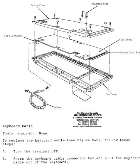
Figure 2-2 Keyboard Assembly
Bottom Cover
Cable Connector
Cable
Keyboard Cable
Tools required: None
ESD Shield
..A~_--Printed Circuit Board
For Service Manuals MAURITRON SERVICES 8 Cherry Tree Road, Chlnnor
Oxford.hlre, OX9 4Qy'
Tel (01844) 351694 Fax (01844) 352554
email:[email protected]
Top Cover
To replace the keyboard cable (see Figure 2-2), follow these steps:
1. Turn the terminal off.
2. Press the keyboard cable connector tab and pull the keyboard cable out of the keyboard.
Keyboard PCB
Tools required: No. 0 Phillips screwdriver
No. 2 Phillips screwdriver
To replace the keyboard PCB (see Figure 2-2), follow these step
1. Turn off the terminal.
2. Unp 1 ug the keyboard cab 1 e from the keyboard.
3.
Turn the keyboard over and remove the six No.2 Phillips screws that attach the keyboard bottom cover to thekeyboard.
4. Lift off the keyboard bottom cover.
5. Remove the No. 0 Phillips screw beneath the spacebar that holds the keyboard top cover to the PCB assembly.
6. Unscrew the three No. 0 Phillips screws and washers that hold the keyboard ESD shield on the keyboard PCB.
7.
Lift the PCB assembly out of the keyboard cover.8. Cover the under side of the new keyboard PCB with the keyboard ESD shield. Replace the screws and washers. Tighten.
9. Fit the new keyboard PCB assembly back into the keyboard t cover.
10. Replace the No. 0 Phillips screw that holds the PCB assemb in place.
11. Reattach the bottom cover of the keyboard assembly.
12. Plug the keyboard cable back into the terminal.
REMOVING AND REPLACING ASSEMBLIES IN THE TERMINAL MODULE
This section describes removing and replacing the terminal
Removing the Terminal Enclosure
Tool required: No.2 Phillips screwdriver
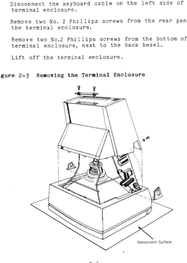
To remove the terminal enclosure (see Figure 23), follow these -steps:
1. Remove all cables and power cords from the rear of the terminal.
2. Rest the display face of the terminal on a nonscratch surface.
3. Disconnect the keyboard cable on the left side of the terminal enclosure.
4. Remove two No.2 Phillips screws from the rear panel of the terminal enclosure.
5. Remove two No.2 Phillips screws from the bottom of the terminal enclosure, next to the back bezel.
6. Lift off the terminal enclosure.
Replacing the Fuse
Tool required: Fuse puller or screwdriver
The terminal has one fuse , rated 2 amps, 125 vo 1 ts. See Figu-re
2-4 for the fuse location on the terminal PCB.
To check or replace the fuse, follow these steps:
1. Remove the terminal enclosure.
2. Use a fuse puller to remove the suspected fuse.
3. Check the fuse. If the fuse is broken or blackened, push a new fuse into the fuse socket.
If the fuse is good, push it back into the fuse socket.
4. Replace the terminal enclosure (see "Replacing the Termina Enclosure" for instructions).
Replacing the Terminal PCB
Tools required: No.2 Phillips screwdriver
Flat-bladed screwdriver
Alligator clips
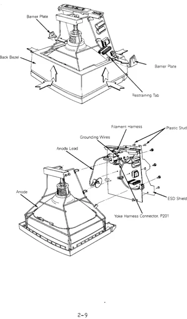
To remove the terminal PCB (see Figure 2-5), follow these steps:
1. Remove the terminal enclosure.
2. Slide the barrier plates mounted on either side of the back bezel out from under the restraining tabs.
3. Leaving the terminal on its face, pull the back bezel off the terminal chassis.
4. Discharge the anode (see "Discharging the Anode" for instructions).
5. Disconnect the anode lead.
6. Disconnect the yoke harness connector, P201, from the termina I P CE.
Warning--Handle the CRT neck carefully. If you break it, flying glass can injure anyone within a radius of six to ten feet.
7. Disconnect the filament harness from the neck of the CRT.
8. Unscrew the two Phillips No.2 screws securing grounding
wires to the CRT chassis.
Caution--Don't remove the Phillips screws directly
underneath the rear panel on the terminal PCB. They fasten the rear panel to the terminal PCB.
9. Remove the four plastic studs securing the ESD shield to the back of the terminal PCB.
10. Loosen any screws holding the ESD shield in place.
11. Remove the ESD shield.
12. Loosen the six No.2 Phillips screws on the underside of the
termina I PCB.
Figure 2-5 Removing the Terminal PCB
Back Bezel
Bamer Plate
Filament Harness
. 4
Plastic StudsGrounding Wires ~/
.~ ~
.-To replace the terminal PCB, follow these steps:
1. Posi tion the ESD shield on the back of the terminal PCB.
2. Replace the four plastic studs that secure it.
3. Position the terminal PCB in its slot in the bezel. Make sure the lever of the brightness potentiometer fits into the brightness slideswitch on the bezel.
4. Tighten the six screws that secure the terminal PCB to the chassis.
5. Reconnect the grounding wires to the chassis.
6. Reconnect the yoke harness to P201 on the terminal PCB.
Warning--Handle the CRT neck carefully. If you break it, flying glass can injure anyone within a radius of six to ten feet.
7. Reconnect the filament harness to the CRT neck.
8. Discharge the anode on the CRT (see "Discharging the Anode."
9. Reconnect the anode lead.
10. Replace the back bezel and both barrier plates.
11. Replace the terminal enclosure and keyboard.
Replacing the CRT/Yoke Assembly
Tools required: No.2 Phillips screwdriver
Flat-bladed screwdriver
Alligator clips
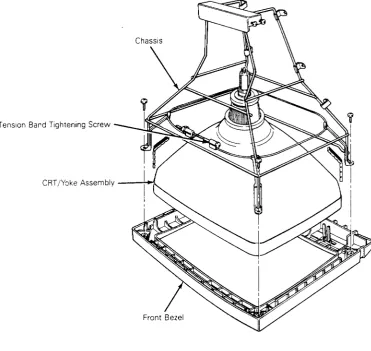
To remove the CRT/yoke assembly (see Figure 2-6), follow these steps:
1. Remove the terminal enclosure, keyboard cable, back bezel, and barrier plates.
2. Remove the terminal PCB and insulation sheet.
Figure 2-6 Removing the CRT/Yoke Assembly
Tension Band Tightening Screw
CRT /Yoke Assembly - - " + ! .
To replace the CRT/yoke assembly, follow these steps:
1. Discharge the anode on the new CRT.
Warning--If you are replacing the same CRT/yoke assembly, you s t i l l need to discharge the anode. A CRT left standing for any length of time will develop a charge from the air, and need to be discharged again.
2. Place the assembly in the front bezel. Make sure the anode faces the keyboard connector jack on the terminal PCB.
3. Fit the chassis back into the bezel.
4. Replace the four No.2 Phillips screws that secure the assembly to the chassis. Tighten.
5. Replace the terminal PCB and insulator sheet.
6.
Make sure the tension band is tight. it.7.
Replace the back bezel, barrier plates, and keyboard cable.8.
Replace the terminal enclosure.Replacing the Yoke
Tools required: None
To remove the yoke, follow these steps:
1. Remove the CRT/yoke assembly from the terminal.
2. Loosen the yoke lock on the neck of the CRT (see Figure 2-7).
3. Remove the yoke.
To replace the yoke, follow these steps:
Warning--Before you reattach the yoke assembly, you must
discharge the anode. A CRT left standing for any length of time will develop a charge from the air, and need to be discharged again.
1. Position the yoke on the neck of the CRT (see Figure 2-7).
2. Tigh ten the yoke lock.
3.
Replace the CRT/yoke assembly in the terminal.Figure 2-7 Replacing the Yoke
Replacing the Terminal Enclosure
Tool required: No.2 Phillips screwdriver
To replace the terminal enclosure, follow these steps:
1. With the terminal "face on a nonscratch surface, reseat the enclosure over the chassis into the back bezel.
2. Replace the two No.2 Phillips screws on the rear of the
terminal enclosure. Tighten.
3.
Replace the two No.2 Phillips screws on the bottom of theterminal. Tighten.
Discharging the Anode
Tools required: Insulated flat-blade screwdriver
Alligator clips
We have written specific warnings throughout this chapter about discharging the anode on the side of the CRT. If you have never discharged the anode, or need a review, follow these
instructions.
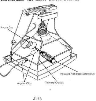
To discharge the CRT anode before removal (see Figure 2-8), follow these steps:
Figure 2-8 Discharging the Anode Before Removal
1. Turn off the terminal and unplug it from its power source.
2. Remove the terminal enclosure.
3.
Ground the shaft of an insulated flat-bladed screwdriver toth~ terminal chassi~ with alligator clips.
4. Slip the blade between the anode cap and the anode. Touch the blade to the wire anode leads under the cap. Listen for a popping or crackling sound.
5. Remove the anode lead.
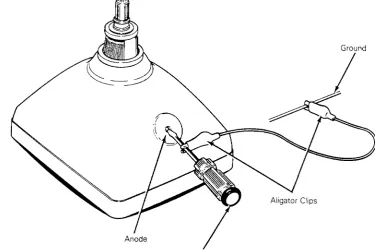
To discharge the anode before installation (See Figure 2-9), follow these steps:
1. Ground the shaft of an insulated flate-bladed screwdriver.
2. Touch the blade of the screwdriver to the anode. Listen for a popping or crackling sound.
3.
Install the CRT.Figure 2-9 Discharging the Anode Before Installation
Ground
3 TROUBLESHOOTING
Before You Start . . . 3-2 Safety . . . 3-2 Required Tool s . . . 3-2
Troubleshooting Quick Reference Guide . . . 3-3
Troubleshooting Flowchart . . . 3-3
Troubleshooting Aids . . . 3-8
Installation Checklist . . . · · · 3-8
Checking for Continuity . . . 3-9
Power Supply Check on the Terminal PCB . . . 3-9
BEFORE YOU START
Safety
Warning--This terminal contains high voltage. Don't attempt to
service the terminal without taking all the precautions necessary for working with high voltage, including the following:
o If you must open the terminal for any reason, turn off the power, disconnect any communication cables, and unplug the terminal.
o Remove any jewelry, especially from your hands and wrists.
o Avoid wearing clothing that holds a static charge.
o Use only insulated or nonconductive tools.
o Whenever you disconnect the anode from the anode lead, make sure to discharge the anode as directed in Chapter 2.
o If you need to remove or replace the CRT/yoke assembly, remember that the CRT can implode if you drop it or break the neck. The flying glass can injure anyone within a radius of six to ten feet.
Required Tools
Before you start to repair in the terminal, make sure you ha ve the tools and materials listed below.
o No.2 Phillips screwdriver
o 3/16-inch flat-bladed screwdriver
o Digital multimeter (or an ohmmeter and voltmeter)
o Test connectors for the MODEM and AUX ports (See Appendix C for instructions to make them or Chapter 5 for ordering information.)
o Nonconductive video alignment tool
. ~
TROUBLESHOOTING QUICK REFERENCE GUIDE
Table
3-1
is a troubleshooting reference guide. Once youdiscover the major symptoms, this table can quickly direct you to
the most likely problem area. However, don't automatically
replace the suggested modules until you've studied the problem or checked related details in the troubleshooting flowchart.
Table
3-1
Troubleshooting Quick Reference GuideSymptom Possible Problem Area(s)
No display Terminal PCB, CRT/yoke assembly
Poor display quality
Wrong size display Crooked
Too bright Not in focus
Fails self-test
Fails diagnostic test
Inoperative keys
Can't communicate with computer
Letters or error codes on the screen
Touch/tilt doesn't respond correctly
Adjustments, terminal PCB
Adjustments, terminal PCB, yoke
Terminal PCB
Terminal PCB, wrong diagnostic setup, faulty test connectors
Keyboard, terminal PCB, keyboard cable
Setup parameters, terminal PCB, communication cable
Terminal PCB
Touch/tilt screw tension
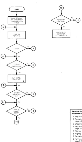
TROUBLESHOOTING FLOWCHART
Read the troubleshooting flowchart and match the symptoms with
the suggested solutions. Any flowchart block that requires a
procedure includes a bold number that is keyed to the legend on
each page of the flowchart. The legend lists the procedure name
Figure 3-1 Troubleshooting Flowchart, page 1 of 4
TURN TERMINAL
OFF DISCONNECT
COMMUNICATION CA3LE
- ..JRN ON
TE;:l"v1I N,:'l,L
RLN SYSTEM DIAGNOSTIC
8
CHECK SE~lP COMPeTE"
DOCJMENTATION
Terminal Troubleshooting Flowchart Legend
1 Replacing the Fuse, page 2-7 2 Replacing the Terminal PCB,
page 2-8
3 Checking the Power Supply, page 4-3 4 Replacing the CRT/Yoke Assembly,
page 2-10
5 Aligning the Brightness, page 4-8 6 Aligning the Display, page 4-6 7 Replacing the Yoke, page 2-12 8 Running the Diagnostic Self-Test.
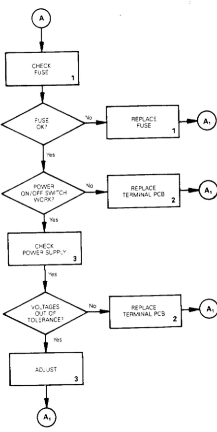
Figure 3-1 Troubleshooting Flowchart, page 2 of 4
CHECK FUSE
CHECK POWE'! SUPPLY
ADJUST
3
3
For Service Manuals MAURITRON SERVICES 8 Cherry Tree Road, Chlnnor
Oxfordshire, OX9 4Qy' Tel (01844) 351694 Fax (01844) 352554
email:[email protected]
REPLACE FUSE
REPLACE TERMINAL PCB
REPLACE TERMINAL PCB
2
2
Terminal Troubleshooting Flowchart Legend
Replacing the Fuse, page 2-7 2 Replacing the Terminal PCB,
page 2-8
3 Checking the Power Supply, page 4-3 4 Replacing the CRT/Yoke Assembly,
page 2-10
5 Aligning the Brightness, page 4-8 6 Aligning the Display, page 4-6 7 Replacing the Yoke, page 2-12 8 Running the Diagnostic Self-Test,
page 3-11
9 Checking the Keyboard, page 3-12 10 Checking the Communications Cable,
page 3-8
Figure 3-1 Troubleshooting Flowchart, page 3 or 4
TURN OFF TERMINAL. REMOVE ENCLOSURE TURN ON TERMINAL
PER"ORM BR:GrlTNESS ALIGNMENT
REPLACE TERMINAL ?CB
5
2
Terminal Troubleshooting Flowchart Legend
No
1 Replacing the Fuse, page 2-7 2 Replacing the Terminal PCB,
page 2-8
REPLAC= TERMINAL PCB
3 Checking the Power Supply, page 4-3 4 Replacing the CRT/Yoke Assembly,
page 2-10
5 Aligning the Brightness, page 4-8 6 Aligning the Display, page 4-6 7 Replacing the Yoke, page 2-12 8 Running the Diagnostic Self-Test.
page 3-11
2
REPLACE TERMINAL PCB
PERFORM FULL MONITOR
ALIGNMENT
REPLACE TERMINAL PCB
6
2
2
REPLACE TUBE
4
REPLACE YOKE
Figure 3-1 Troubleshooting Flowchart, page 4 of 4
PERFORM KEYBOARD
CHECK 9
CHECK COMMUNICATIONS
CABLE 10
CHECK HOST SOFTWARE
No REPLACE WITH
No
KNOWN GOOD KEYBOARD 11
REPLACE OLD KEYBOARD
REPLACE CABLE
No REPLACE
TERMINAL PCB
Terminal Troubleshooting Flowchart Legend
1 Replacing the Fuse, page 2-7 2 Replacing the Terminal PCB,
page 2-8
3 Checking the Power Supply, page 4-3 4 Replacing the CRT/Yoke Assembly,
page 2-10
5 Aligning the Brightness. page 4-8 6 Aligning the Display. page 4-6 7 Replacing the Yoke. page 2-12 8 Running the Diagnostic Self-Test.
page 3-11
9 Checking the Keyboard. page 3-12 10 Checking the Communications Cable.
page 3-8
11 Replacing the Keyboard. page 2-3
.-TROUBLESHOOTING AIDS
This section contains a number of specialized procedures to help you repair the terminal. Most of them are referenced on the troubleshooting flowchart.
Installation Checklist
The checklist in Table 3-2 helps you quickly check terminal installation. If a user installs the terminal incorrectly, it may not function properly. If you can't find the problem, improper installation may be the key.
Table 3-2 Terminal Installation Checklist
Environment
Room temperature is between +40 and +91 degrees Fahrenheit (5 and 33 degrees Celsius).
Terminal isn't near a magnetic field.
Keyboard
Keyboard cable is in the keyboard connector jack on the left side of the terminal.
Keyboard cable is in the connector jack on the rear of the keyboard.
AC Power Cord
Female end of the power cord is plugged into the AC power socket on the rear panel of the terminal.
Male end of the power cord is plugged into the wall socket.
Communication Interface Cable
One end of the RS-232C interface cable is connected to the MODEM port on the terminal's rear panel.
Table 3-2 Continued
Computer Interface
You'll need to check the computer's documentation to determine the following information:
Correct baud rate
Correct stop bits
Correct data bits
Correct parity type
Correct handshaking protocol
Checking for Continuity
Sometimes you can fix the problem without opening the terminal.
The problem could be a damaged cable or power cord. Sometimes,
you may need to open the terminal to check the fuse or internal
connections. Check this list, then, with an ohmmeter, check the
continuity of the components listed below.
Outside the terminal, check the
o Power cord
o Communication cable (supplied with the computer)
Inside the terminal, check the
o Fuse
o AC power input receptacle (on the rear panel of the
terminal)
o Terminal PCB to the CRT/yoke wiring harness
Hold the probes in place for five seconds, or until the ohmmeter
settles, to ensure an accurate reading. If the part in question
is open, replace it.
Power Supply Check on the Terminal PCB
Tools required: No.2 Phillips screwdriver
Digital multimeter
Nonconductive video alignment tool
To check the voltages, follow these steps:
1. Turn the terminal off.
2. Remove the terminal enclosure.
3.
Attach one lead from the DMM to the chassis as ground.4. Turn the terminal on.
5. With the other lead from the DMM, look for these voltages at these points on the terminal PCB:
Voltage
+5V ~5%
+12V +5%
-12V ~5%
Point
R15
C27
C31
6. If one or more of these voltages are not in tolerance, adjust VR101.
7.
If you adjust VR101, and the voltage or voltages are still not within tolerance, replace the terminal PCB.Power-on Self-Test
The power-on self-test checks the terminal's random-access memory (RAM), read-only memory (ROM), electrically eraseable read-only memory (EEROM), and external communication ports.
Each time you turn the terminal on, the power-on self-test
Table 3-3 Power-On Self-Test Error Messages
Error
Message Failure
K
o
x
C
A
y
9
P
EEROM chedksum error
RAM error
MODEM port TXD/RXD error
MODEM port DTR/DCD error
MODEM port RTS/CTS error
AUX port error
EEROM read/write error
PROM checksum error
Diagnostic Self-Test
The terminal diagnostic self-test routine starts in setup mode. This test routine includes communications circuitry tests,
read/write tests, and row buffer tests. Two special test
connectors allow the diagnostic test to function (see Appendix C for connector definitions or Chapter 5 for ordering information). After you start it, the diagnostic test continues to run until you stop it. If the test detects an error, an error message appears in the lower right-hand corner of the screen (see Table
3-4 for error message de fini t ions).
Follow these steps to start the diagnostic self-test:
1. Turn the terminal off.
2. Detach any communications cables on the back of the terminal.
3. Attach the test connectors to the MODEM and AUX ports that are on the rear panel of the terminal.
4 .
5.
6.
7.
Note--See Appendix C for a description of these test
connectors and instructions for making them.
Turn the terminal on.
Hold the SHIFT key, then press the SETUP key.
Press CURSOR DOWN five times. Look for to the TEST:OFF field in the setup line at the bottom of the screen.
8.
Press the spacebar. This toggles the TEST field ON.9. Hold SHIFT, then press SETUP. flashing test pattern.
Press N. You should see a
10. Look for one of the error messages found in Table
3-4.
Note--To fully test the terminal, let the diagnostic self-test run five minutes.
11. If you see an error message, replace the terminal logic PCB; if you don't see an error, press SETUP twice.
12. Turn the terminal off. Remove the test connectors, and reattach the communications cables.
Table
3-4
Diagnostic Self-Test Error MessagesError
Message Failure
A RTS to CTS data communications error on MODEM port
C DTR to DCD data communications error on MODEM port
K EEROM data check sum error
o
RAM errorX Transmit/receive data error on MODEM port
Y Printer port error
9 EEROM read/write diagnostic self-test error
P Program ROM check sum error
Checking the Keyboard
If you suspect the keyboard is the source of the problem, follow this procedure to verify it:
1. Turn the terminal off.
2. Disconnect the communication cable.
6. Type on the keys. Test a 11 the keys in shi fted and
unshi ft ed pos it ions. I f the ke ys don It respond, see sect ion E of "Troubleshooting Flowchart."
Isolating Circuits
If you troubleshoot to the component level using the schematics in Chapter
7,
you may want to isolate the logic, monitor, or power supply circuitry. Table3-5
is a list of jumpers on the terminal PCB and the areas they isolate. For an exact location, see the terminal PCB component layout in Chapter 5.Table
3-5
Terminal PCB Circuit Isolation JumpersJumper Areas Isolated
J525 Ground from logic
J526
J524 Power supply from logic
J527
J543 Video circuit
Logic from monitor circuitry
J522 Vertical synchronization
Logic from monitor circuitry
J545 Horizontal synchronization
Logic from monitor circuitry
J725 Dim circuit
4 ADJUSTMENTS AND ALIGNMENTS
Before You Start . . . 4-2
Safety ... 4-2 Tools Required . . . 4-2
Power Adjustments ... 4-3
Does the Terminal Meet the Display Specifications? . . . 4-4
Aligning the Terminal Display . . . 4-6
Adjustments . . . 4-7
Height . . . 4-7
Vertical Hold . . . 4-7
Lineari ty . . . 0 0 0 0 0 0 0 0 0 0 0 0 • • • • 0 • • • • • • • • • • • • • • 4-8
Brightness . . . 0 • • • • • • • • • • • • • • • 0 • • • • • • • • • • • • • • • • • 4-8
Focus ... 4-9 Wid th . . . 0 • • • • • • • • • 0 • • 0 0 • • • • 0 • • • • • • • • • • • • • • • • • • • • 4-9
Display Leveling . . . 0 • • • • • • • • • • • • 0 . 0 • • • • • • 0 • • • • 0 0 • • • • • • 4-9
Display Magnets 0 0 0 0 • • • • • • • • • • • • • • • • • • • • • • • • • • • • • • • • • • • • • 4-11
BEFORE YOU START
Safety
Warning--This terminal contains high voltage. Don't attempt to
service the terminal without taking all the precautions necessary for working with high voltage, including the following:
o If you must open the terminal for any reason, turn off the power, disconnect any communication cables, and unplug the terminal.
o Remove any jewelry, especially on your hands and wrists.
o Avoid wearing clothing that holds a static charge.
o Use only insulated or nonconductive tools.
o Whenever you disconnect the anode from the anode lead, make sure to ground the anode as directed in Chapter 2,
"Discharging the Anode."
o If you need to remove or replace the CRT/yoke assembly, remember that it can implode if you drop it or break the neck. The flying glass can injure anyone within a radius of six to ten feet.
Tools Required
Before you test the power supply voltages or make any adjustments to the power supply or monitor assemblies, make sure you have the tools listed below.
o Flat-bladed nonconductive alignment tool
o Hex nonconductive alignment tool
o No. 2 Phillips screwdriver
o Digital voltmeter
o Oscilloscope
o Millimeter ruler or reticle (optional--see Appendix D for instructions on how to use the reticle when you align the terminal display)
, .:
POWER ADJUSTMENTS
The monitor/power supply PCB provides all of the voltages for the logic (+5V, +12V, and -12V). You can adjust the +5 supply.
Note--You can find the locations of all components and test points referred to in this chapter in Figure 4-1.
Figure 4-1 Power Supply Component Layout
To adjust the power supply, follow these steps:
1 . Turn the termina I off.
2. Unplug the power cord from the back of the terminal. If communications cables are attached to the back of the terminal, detach those, too.
3.
Place the terminal on its face and remove the terminal enclosure and back bezel (see Chapter 2).4. Plug the terminal into an AC power source.
8 .
9.
Note--If you can't bring the +5V supply into tolerance, see Chapter 3, "Troubleshooting."
Check the -12V supply at C31 on the terminal PCB. The digital voltmeter shou'ld read -12V (+5 percent). If the -12V supply is not within tolerance after you have adjusted the +5 supply, see Chapter 3, "Troubleshooting."
Check the +12V supply at C27 on the terminal PCB. The digital voltmeter should read +12V (+5 percent). If the +12V supply is not within tolerance after you have adjusted the +5 supply, see Chapter 3, "Troubleshooting."
10. Turn the terminal so the screen is visible. Set the
terminal PCB on a surface where the traces will not touch other metal.
11. Check to see if the display needs alignment. (See "Does the Terminal Meet the Display Specifications?") If it doesn't need alignment, turn off the terminal, unplug it, and replace the top cover.
If the display needs alignment, go to "Aligning the Terminal Display."
DOES THE TERMINAL MEET THE DISPLAY SPECIFICATIONS?
Before you adjust the display on the monitor, measure the screen margins and study the display, following the procedure below.
Note--If you have just finished checking and adjusting the power supplies, go to step 4.
1. Turn the terminal off.
2. Unplug the power cord from the back of the terminal.
3. If any communications cables are attached to the back of the terminal, detach them.
4. Attach the test connectors to the MODEM and AUX ports on the rear pane 1.
Note--See Appendix C for a description of these connectors and instructions for making them. See Chapter 5 for
ordering information.
5. Plug in the power cord and turn the terminal on. Let it run for 30 minutes.
6. Hold the SHIFT key, then press the SETUP key.
7. Press CURSOR DOWN fi ve times. Look for the TEST:OFF field in the setup line at the bottom of the screen.
8. Press CURSOR RIGHT four times.
9. Press the spacebar. This toggles the TEST field ON.
10. Hold the CTRL key, then press the SETUP key. Press the N key. You should see a flashing test pattern.
11. Hold down the spacebar until the test pattern stops flashing.
12. Margins on the top, bottom, and both sides should measure 11mm (+2mm). If they don't, see the next section,
"Alignlng the Terminal Display."
13. Look at the display. Do you see any of these problems?
o Barreling (display edges that curve outwards)
o Pincushioning (display edges that curve inwards)
o Display edges aren't straight
o Display is too wide or too narrow
o Display is too high or too short
o Display isn't centered or level
o Poor focus
o Too dim or too bright
o Poor contrast
For Service Manuals MAURITRON SERVICES 8 Cherry Tree Road, Chlnnor
Oxfordshire, OX9 4Qy'
Tel (01844) 351694
Fax (01844) 352554
emall:[email protected]
o Letters at the top of the pattern are a different size than the letters the bottom
o Letters aren't uniform throughout
If you find any of the problems mentioned here, go to the next section, "Aligning the Terminal Display."
ALIGNING THE TERMINAL DISPLAY
Warning--The CRT/yoke assembly has high voltages. Only qualified service personnel should perform these adjustments.
The monitor has several alignments and adjustments. If the terminal display is out of tolerance in one or two areas, make adjustments to correct only those problems. If you change the CRT/yoke assembly or the terminal PCB, you must perform a full alignment. Peform these procedures only if the display is out of tolerance and doesn't match the specification.
Note--If you already have the test pattern on the screen, go to step 9.
To align the terminal display, follow these steps:
1. Turn the terminal off.
2. Disconnect the communications cables and power cord.
3. Attach the test connectors to the MODEM and AUX ports on the rear panel.
Note--See Appendix C for a description of these connectors and instructions for making them.
4. Plug the power cord into the back of the terminal and turn it on. Let it run for 30 minutes. (If it has already run for 30 minutes, continue the procedure.)
5. Hold the SHIFT key, then press the SETUP key.
6. Press CURSOR DOWN fi ve times. Look for the TEST:OFF field in the setup line at the bottom of the screen.
7. Press CURSOR RIGHT four times.
8.
Press the spacebar. This toggles the TEST field ON.9. Hold the CTRL key, then press the SETUP key. Press the N key. You shou I d see a f lashing test pattern.
10. Hold down the spacebar until the test pattern stops flashing.
11. Adjust the display. Check Figure 4-1 for component locations.
Table 4-1 Display Problems and Adjustments
Display Problems
Letters at the top of the display aren't the same height as those at the bottom of the display
Fuzzy letters
Too bright; too dim; raster scan lines show; individual problems with or dim
Display too short or too tall
Too wide or too narrow
No vertical hold
Not centered
Not level
Pincushioning, barreling, crooked edges, corners sag or move out of specification
ADJUSTMENTS
Adjustments
Linearity
Focus
Brightness
Height
Width
Vertical hold
Centering rings
Yoke lock
Disp lay magnets
Page
4-8
4-9
4-8
4-7
4-7
4-7
4-12
4-9
4-10
This section contains detailed instructions for each adjustment mentioned in Table 4-1. Figure 4-2 can help you to identify adjustment locations on the terminal PCB.
Height
The height adjustment is labeled VR302 on the terminal PCB. Adjust VR302 until the top edge and the bottom edge of the display are both 11mm C+2mm) from the edge of the bezel.
Vertical Hold
Figure 4-2 Adjustment Locations
L202, Width
VR201, Focus
VR202, Full Brightness
VR303, Linearity
Linearity
The linearity adjustment is labeled VR303 on the terminal PCB. Adjust VR303 until characters on the bottom of the display are the same height as those on the top.
Brightness
You can adjust bright and dim separately. Although you can adjust them independently, it's a good idea to adjust bright first, and then dim.
1. Slide the brightness slideswith as far right as possible (full brightness).
2. Turn VR202 on the terminal PCB as far clockwise as possible. You should see the raster lines on the screen.
4.
Focus
Compare the full bright line-blocks in the test pattern to the dim line-blocks in the test pattern. If dim looks either too bright or not bright enough, adjust VR401 until the contrast looks correct.
Note--Do not use the focus control to adjust the outer
extremities of the screen. Some focus distortion happens in any CRT.
The focus adjustment is labeled VR201 on the terminal PCB.
Adjust VR201 until the characters halfway between the center of the display and the bezel are distinct and clear.
Width
Caution--Do not use a metal tool to adjust the width coil. The
magnetic properties of a metal tool will affect the adjustment.
The width adjustment is labeled L202 on the terminal PCB. With a hex nonconductive alignment tool, adjust L202 until either side of the display is 11mm (~2mm) from the edge of the bezel.
Display Leveling
The yoke lock is located on the neck of the CRT (see Figure 4-3).
To level the display, follow these steps:
1. Loosen the yoke lock on the neck of the CRT.
2. Rotate the yoke until the top and bottom edges of the display are level with the top and bottom of the bezel.
3. Tighten the yoke lock.
Warning--Do not tighten the yoke lock too much or the neck of the
Figure 4-3 Yoke Lock on the CRT Neck
Rotate Yoke To Level Display
r~ ~
--=--
-=---:
-=-=
-=-=-
=
II
I
II
II I
i
I
I
I
i
I
I
Yoke
Yoke Lock
Display Magnets
There are eight display magnets on a ring around the yoke. When turned, they change corresponding screen areas. They can also affect adjacent areas. Figure 4-4 identifies each magnet; Table
4-2 identifies which portion of the screen each changes.
Figure 4-4 Display Magnets
Table 4-2
Magnet Number
2
3
4
5
6
7 3
5
Screen Areas Affected by Display Magnets
Area Affected
Top
Upper left corner
Left
Lower left corner
Bottom
Centering Rings
There are two display centering rings around the yoke. When
turned, they move the display position on the screen. Figure 4-5 shows the rings. If the display isn't in the center of the
screen, tu~n the rings until" it is, then make height and width adjustments described on pages
4-7
and4-9.
Figure 4-5 Centering Rings
5 ILLUSTRATED PARTS LIST
Introduction . . . 5-2 Terminal Display Assembly Exploded View . . . 5-3 Keyboard Assembly Exploded View . . . 5-4
Terminal Components List . . . 5-5
INTRODUCTION
This chapter provides the information you need to order parts for the termina 1.
The first part of this chapter provides two exploded assembly drawings: Figure 5-1, the terminal display, and Figure 5-2, the keyboard. Each replaceable assembly, plastic covering, or cable is labeled on the drawings with a specific part name and part number. When you order replacement parts, please give both the part name and the part number.
In the second part of this chapter, we list all piece parts, their values or generic industry numbers when relevant, and locations on the terminal PCB or the keyboard PCB. Table 5-1
Figure 5-1
Enclosure Assembly 830017-01
Back Bezel Assembly 830018-01
Terminal Display Assembly Exploded View
===~
Barner Plate, Power On/Off (AC Switch) 710049-01
Module Jack 560009-01
Pow 340(
Figure 5-2 Keyboard Assembly Exploded View
Module Jack
560009-01
Keyboard Cable
94-038-03
Keyboard Assembly 840013-01
Keyboard peBA
Table 5-1 Terminal PCB Components List
Part Number Description
Integrated Circuits
230129-01 250220-01 80-300-02 80-400-00 80-400-04 80-400-09 80-400-11 80-400-15 80-400-24 80-400-26 80-400-27 80-400-29 80-400-34 80-400-64 80-430-04 80-431-12 80-431-34 80-431-40 80-432-00 80-432-01 80-432-15 80-432-20 80-432-23 80-435-12 80-520-10 Resistors 80-161-29 80-161-37 80-161-38 80-161-39 80-161-40 80-161-43 80-161-46 80-163-03 80-900-00 80-900-02 80-900-04 80-900-05 80-900-08 80-900-11
ASY FIRMWARE CHAR. GEN. PRO ASY FIRMWARE PROGRAM PROM PPT BEEPER,AUDIO
PPT IC 74LSOO PPT IC 74LS04 PPT IC 74LS139 PPT IC 74LS174 PPT IC 74LS374 PPT IC 74LS132 PPT IC 74LS74 PPT IC 74LS283 PPT IC 74LS158 PPT IC 74LS138 PPT IC 74LS368
PPT IC 4016 2K x 8K STATIC RAM PPT IC 2661-B
PPT IC CRT CNTL 6845RA 2MHZ PPT IC 68BOO MICROPROCESSOR PPT IC 1488
PPT IC 1489
PPT IC ADJ. SHUNT REGULATOR PPT IC TDA 1170N
PPT IC 4N35
PPT IC GATE ARRAY (VIDEO) ER5911A 1024 BIT EEROM
PPT RES. ,VAR.1K OHM PPT RES. ,VAR.100K-B PPT RES. ,VAR.100K-B PPT RES. ,VAR.200K-B PPT RES. ,VAR.2MEG-B PPT RES.,VAR.500 OHM PPT RES.,VAR.100K-A
PPT THERMISTOR SG-15 50HM 1A PPT RES, CF 100 OHM 1/4W 5%
PPT RES, CF 470 OHM 1/4W 5%
PPT RES, CF 680 OHM 1/4W 5%
PPT RES, CF 1K OHM 1/4W 5%
PPT RES, CF 10K OHM 1/4W 5%
PPT RES, CF 3.3 OHM 1/4W 5%
PPT RES, CF 47 OHM 1/4W 5%
Location U12 U18 B1 U4 U14,U5 U29 U24 U13,U15,U16 U20 u26 U7,U9 U3,U6,U8 U23 U19 U 1 , U2 U22 Ul0 U17 U27 U28 IC102 IC301 IC101 U 11 U25 VR101 R221 VR303
Table 5-1 Continued
Part Number Description
Resistors (continued)
80-900-20 80-900-21 80-900-22 80-900-23 80-900-24 80-900-31 80-900-33 80-900-35 80-900-37 80-900-39 80-900-46 80-900-58 80-900-65 80-900-69 80-900-89 80-900-90 80-900-93 80-901-04 80-901-50 80-901-63 80-901-69 80-901-71 80-901-76 80-904-03 80-904-15 80-904-42 80-904-50 80-905-43 80-905-64 80-905-66 80-905-69
PPT RES, CF 68K OHM 1/4W 5%
PPT RES, CF 150K OHM 1/4W 5%
PPT RES, CF 270K OHM 1/4W 5%
PPT RES, CF 470K OHM 1/4W 5%
PPT RES, CF 12K OHM 1/4W 5%
PPT RES, CF 4.7K OHM 1/4W 5%
PPT RES, CF 120K OHM 1/4W 5%
PPT RES, CF 100K OHM 1/4W 5%
PPT RES, CF 82 OHM 1/4W 5%
PPT RES, CF 2.2K OHM 1/4W 5%
PPT RES, CF 22K OHM 1/4W 5%
PPT RES, CF 1MEG, 1/4W 5%
PPT RES, CF 220K OHM 1/4W 5%
PPT RES, CF 62 OHM 1/4W 5%
PPT RES, CF 15K OHM 1/4W 5%
PPT RES, CF 33 OHM 1/4W 5%
PPT RES, CF 10 OHM 1/4W 5%
PPT RES, CF 57 OHM 1/4W 5%
PPT RES, CF 180K OHM 1/4W 5%
PPT RES, MOF 12 OHM 2W 5% PPT RES, WW 1.5 OHM 3W 5% PPT RES, MOF 1K OHM 2W 5% PPT RES, CF 330K 1W 5%
PPT RES, CF 120K OHM 1/2W 5%
PPT RES, CF 1 OHM 1/2W 5%
PPT RES, CF 3K OHM 1/4W 5%
PPT RES, CF 10 OHM 1/2W 5%
PPT RES, MOF 33 OHM 1W 5% PPT RES, CF 220K OHM 1/2W 5%
PPT RES, MOF 560 OHM 1W 5% PPT RES, MOF 1K OHM 5W 5%
Crystals, Coils, Diodes, Transistors
410009-01 410010-01 410011-01 80-006-06 80-170-01 80-170-19 80-170-24 80-170-25 80-170-43 80-170-44 80-170-47 80-170-55 80-170-66
PPT COIL, HOR. WIDTH
PPT COIL, HOR. LINERARITY PPT COIL, DYNAMIC FOCUS PPT COIL, 10UH CHOKE PPT DIODE, IN914B PPT DIODE, V09C PPT DIODE, RGP5020 PPT DIODE, RGP30G
PPT DIODE, IN4937 1A/600V PPT DIODE, IN4004 1A/400V PPT DIODE, SB 350 3A/50V PPT DIODE, IN747A
PPT DIODE, V19E
Table 5-1 Continued
Part Number Description
Crystals, Coils, Diodes, Transistors (continued)
80-170-61 80-170-68 80-110-69 80-170-78 80-170-19 80-170-80 80-180-02 80-180-04 80-180-06 80-180-07 80-180-25 80-180-48 80-180-65 80-180-46 80-190-05 80-600-25 80-690-23 Capacitors 80-920-04 80-920-09 80-920-11 80-920-25 80-920-29 80-920-34 80-920-36 80-920-41 80-920-54 80-920-92 80-920-93 80-920-94 80-920-98 80-930-00
PPT DIODE, V11N PPT DIODE, 1 S2016
PPT DIODE, ZENER HZ6C2 PPT DIODE, 1N5397
PPT DIODE, U19C
PPT DIODE, ZENER HZ3B2 PPT TRANSISTOR, 2N2222 PPT TRANSISTOR, 2N2906 PPT TRANSISTOR, 2N2369 PPT TRANSISTOR, BU406 PPT TRANSISTOR, 2SC3150 PPT TRANSISTOR, 2SC1213 PPT TRANSISTOR, BSX-32 PPT TRANSISTOR, BSX-59 PPT LED, 5219
PPT COIL, CHOKE 10UH 1.5A
PPT CRYSTAL, 19.6614MHZ HC18/W
PPT CAP., CD .01MF 1KV PPT CAP., CD .001MF 50V PPT CAP., MG .1MF 50V AXIAL
PPT CAP., CD 1000PF 500V
PPT CAP., MG 220PF 50V (AXIAL)
PPT CAP., CD 680PF 50V PPT CAP., 22PFAXIAL 50V
PPT CAP., MG 330PF 50V K PPT CAP., MPF .22MF 100V PPT CAP., CD 560PF 1KV K Y5P PPT CAP., CD 330PF 500V K Y5P PPT CAP., CD 1000PF 1KV Z PPT CAP., CD 100PF 50V K Y5P PPT CAP., AEL 10MF 16V
PPT CAP., AEL 41MF 25V VT. MNT.
Location D203 D401 D402,Z1,Z2,Z3 D101,D102,D103 D104 D201 D404 Q102,Q403 Q1 Q401 Q202 Q101 Q201 Q402 SUB DS1 L102,L103 X1 C210 C204 C8,C9,C10,C11,C12 C120,C121,C122, C123,C124,C125, C13,C14,C19,C216, C24,C25,C26,C21, C3 , C30 , C31 , C32 , C33,C36,C41,C6,C7 C215
C15 ,C16 ,C17 ,C18 C20,C21,C22,C 23 C305,C30 8
C34,C35,C40,C42, C43
Table 5-1 Continued
Part Number Description
Capacitors (continued)
80-930-43 80-930-51 80-930-58 80-930-82 80-930-84 80-930-86 80-930-89 80-930-92 80-940-06 80-940-17 80-940-19 80-940-30 80-940-49 80-940-66 80-940-67 80-950-02 80-960-01 80-960-02 80-960-03 80-960-20 80-960-25 Transformers 4200028-01 4200029-01 4200030-01 4200031-01 680002-01
PPT CAP., AEL 1000MF 16V VT. MNT. PPT CAP., AEL 2200MF 16V
PPT CAP., AEL 100MF 16V PPT CAP., AEL 100MF 16V PPT CAP., AEL 100MF 63V PPT CAP., AEL 220MF 200V PPT CAP., AEL 2200UF 10V, 85 DEGREE C
PPT CAP., AEL 6.8UF 35V PPT CAP., MPF .39MFD 100V PPT CAP., PPN .022MFD 400V PPT CAP., MPF .1MFD 100V
PPT CAP., PPN .018MF 630V 5% PPT CAP., PEE .22MF 50V 5% PPT CAP., PPN .22UF 630V J
PPT CAP., PEE .22UF 100V K PPT CAP., MICA 56PF
PPT CAP., INTERF. SUPP., .47MFD 250VAC
PPT CAP., INTERF. SUPP., . 1 MFDI 250VAC
PPT CAP., .0047MFD 250VAC-Y PME271YA4L470M FIF PPT CAP., MG 1000PF/50V KX7R PPT CAP., MK 200PF 50V J NPO
PWR TRANSFORMER EI-40 DRIVE TRANSFORMER
HOR. DRIVE TRANSFORMER FLYBACK
LINE FILTER, COMMON CHOKE 18MH
Table 5-2 Keyboard Components List
Part Number
80-170-01 80-170-69 80-435-13 80-900-39 80-900-93 80-904-47 80-920-11 80-930-35 80-960-05 Description
PPT DIODE, IN914B
PPT DIODE, ZENER HZ6C2 PPT IC KEYBOARD GATE ARRAY PPT RES, CF 2.2K OHM 1/4W 5%
PPT RES, CF 10 OHM 1/4W 5%
PPT RES, CF 24K OHM 1/4W 5%
PPT CAP., MG .1MF 50V AXIAL PPT CAP., AEL 470MF 6.3V
PPT CAP., MG .0015MF 50V K X7R
Ul I
\,Q
~
~ ~
f f
0
'2II
~bOI.
8 7C~ J.'05~J50~'" ~
VRIOI.IO~
\~) -++- (~\ I C7 BLK WHT ICIOI CIII 1
T
~ -41~ \...J 0101 C108 ) 1 0 2 , I Q T
E
t
n CID c E Ql02'" , - - - , , / , n T2Q.
0103 010. 1\V
~ 1. (J E \ / 'B~/--JI03---- W ~ 102 VR2O<el05 CI06 - - H - - (~\ T I J505 ~
R1I511 FIOl 0102 V 8 CRIO "" I ~ Rll0 Cl
CIOI ~ -
D
-.rv- - - RI03 CI'')-- '\ ~ f f C==:J 123QV 0101 J501 RIDl .,... J504 \.J.,. !
1
rW]
Ef
Cl03
lCIO. RII3
~ C~,'*B
2C~2~'
•~
" . ,16
I'~'--
C/3.,. C37 J507/t-
J50J950:2ffOOO~_~
-~
r
lrml
1r
cI181~
f
I 01O.C121~~~
0106 CJ6I
t
03
c=:J 05. C2
:l~1 - - T T 0 f 1 fJTp R1J'l 9 J7o,} 1 CJ ~1 81
".. ~ T LID] 0 GP,} T J!'l14 J~16 -·n- 8 E 03
~
I Cl02 Jib! '("T'f Cl~~19 ~ GPJ ) 5 1 3 / , ~1--/ ~ (I R5 Z VR203O
'J70 nO) J515 J71] R6 ~0
a
TR1O! lID2 I-- • I :~=P/04~=- U19 ---. U25 GP4.... Q CI22 U13 ___ -m'" __ : c-<---~
Ill. CII3 ° CII5 C2.
I
~ C5 Oij :::"Al>~::: J532 ~ 0VR303 V0301 V0302 ~ ~
1
=If
_--J~aL /-J713T GPS L:.. ! "-- 0_9___
:II
J53-4 U24fG V0202 GON T T 0 G~ 0108 T C6 f T : : l m : : : ; /
I ~
0
C30. C302 BON U12? ] ~107 0 GPIO J7J5: : l ]l2 -L -H- ~I- -u- ~ -tJ- llO" ~12" J525 J529 T
fl·' .
·J717 '~
C215 ~c OJ 030J CI23 ~ ~ J526 - - .,----, 02. C8: :J/'6 ' : J535 J537O 0 5 ~ R302 ~ R224 ~ RIDS J523 - - _ _ J530 _ II ~I u.... I ' , : • / I . GPII .
-l3 BlU ~ R3D4 41-CJ12 --""""""-J5ISC311 ~ Rl07 B IIJ524
1
1 J53I OGP9 T :::J7I.0
~~
--<I-- -+ ~ - - 0e
n J52 J528 C261 Ull J7JB J7J. - . ~ J5J6 J53.C2l3 C301 R301 ~.Ly . "
-===-lC20
f
~ R30S IC301 ~ --!!W- GP7 CIl7q
OGP