University of Twente
Faculty EE-Math-CS
Department of Electrical Engineering
Supervisors prof.dr.ir. J. van Amerongen dr.ir. J.F. Broenink
dipl.ing. B. Orlic
January 2004
Report 002CE2004
Control Engineering Department of Electrical Engineering
University of Twente
Fault Tolerance in Real-time Distributed
System Using the CT Library
Hany Ferdinando
Summary
Fault tolerance is more and more important nowadays. The role of computer in industries cannot be neglected. The computers that control machines are often inter-connected via fieldbuses. This can be CAN (Control Area Network), I2C (Inter Integrated Circuit), Spacewire,
etc.
The goal of this project is to build a fault tolerant distributed system using the CT (Communicating Thread) Library. The CT Library offers an Application Programming Interface (API) for CSP (Communicating Sequential Process) programming in popular programming languages.
Fault tolerance itself is too general. Therefore, this project implemented the fault tolerance on communication links in a distributed system. In case of a network failure, the system will switch to the alternative one.
The system was implemented on the ADSP-21992 EZ-KIT LITE board from Analog Devices, Inc. This chip has a CAN bus interface for Control Area Network application.
This project used the CTC (the CT Library for C). In the application on a specific processor, the CT Library needs addition of hardware dependent part, encapsulated in link driver objects and the context switch mechanism. The link driver part will encapsulate all hardware related operation into specific place in order to maintain portability of the CT Library. Therefore, a programmer can use the same program on different processors by changing its link drivers and context switch. This enables single processor to do parallel processing. This is a kernel function to handle parallel programming in a general-purpose processor.
Here, the link driver concept of Hilderink was extended by dividing the link driver object into a Remote Link Driver and a Network Device Driver. The Remote Link Driver is a link driver that provides general purposed methods for communication, while the Network Device Driver is abstract class of all board and fieldbus protocol dependent part of communication.
This project used two communication links, i.e. CAN (Control Area Network) and SPORT (Serial PORT). Both need their own link driver.
Preface
With this project, I finished my study to get a Master degree at the University of Twente, the Netherlands. I am interested in embedded control systems since more and more devices are built using this approach. Using a processor in embedded application is a challenging task, because one has to deal with limited resources.
There are lots of people whom I cannot forget. Prof. Job van Amerongen was the first person I met in this group. He is the program director of my study. I discussed all my subjects with him. Through his guidance, I could choose my subjects fit to my specialization.
I would like to thank to Jan Broenink as my supervisor. He has taught me how to manage my project well. Sometimes he visited me while I am working in my project and we had a talk for a while. Kruidnoten! I could not forget these cookies. He made me to taste it.
Bojan, my daily supervisor has guided me to finish my thesis. He always came to visit me when he went out from his room. From our discussion, I got many inspirations to solve my problem in programming.
Gerald was also helpful. He taught me how to write a link driver for my thesis. When I was programming this link driver, he always asked me how my link driver is. This gave me such a motivation to make it works. Thank you, Gerald!
Also to my friends in Embedded System group: Dusko, Peter, Thiemo and Marcel. We had a great time every Tuesday morning for discussion. You guys have been my supporter for my thesis.
I also got lots of support from my International Bible Study group. Thank you for your prayer. I could not make this without God’s help and you all have done great things in my life.
My friends in Petra Christian University, Surabaya, Indonesia never stopped to encourage me to finish my study. They have done their best effort to support me.
Last but not least, I know that lots of support has come from my own family. They supported me with their own way and I like it.
I know that I can do all things through Christ who strengthens me (Philippians 4:13)
Enschede, January 2004
Content
1 Introduction 1
1.1 Context 1
1.2 Goal and Constraint 3
1.3 Outline of the Report 4
2 Background 5
2.1 Fault tolerance – General Overview 5
2.1.1 Fault – Error – Failure 5
2.1.2 Role of Fault Tolerance 6
2.1.3 Fault Tolerance Method 6
2.2 Distributed System 7
2.2.1 Physical Model 7
2.2.2 Logical Model 8
2.3 ROPES Development Cycle 8
2.4 The CT Library 9
2.4.1 Context Switch 9
2.4.2 Link Driver 9
2.5 The CAN bus 10
2.6 The SPORT (Serial Port) 13
2.7 The ADSP-21992 14
2.7.1 CAN in the ADSP-21992 15
2.7.2 SPORT in the ADSP-21992 16
2.8 Hardware of the Plant 17
3 Software and Hardware Design 19
Fault-tolerance in real time distributed system using The CT Library
3.1.1 setjmp() function 20
3.1.2 longjmp() function 20
3.2 Embedded System Requirement 21
3.3 Extension of Link Driver Concept 21
3.4 Description of Transmit and Receive Process 24
3.5 Fault Tolerance in the CT Library 25
3.6 Hardware of the Plant 26
3.6.1 Potentiometer 27
3.6.2 H-bridge 27
3.6.3 LED indicator of link availability 27
4 Implementation 29
4.1 Object-Oriented Programming in C 29
4.2 Context Switch Implementation 29
4.3 Peripheral LinkDriver Implementation 30
4.3.1 ADCLinkDriver 30
4.3.2 AuxPWMLinkDriver 31
4.3.3 EIULinkDriver 31
4.4 Communication LinkDriver Implementation 32
4.4.1 RemoteLinkDriver 33
4.4.2 NetworkDeviceDriver 33
4.5 Altering Code to Achieve Fault Tolerance 35
5 Experimental Results 37
5.1 Experiment with simple producer-consumer 37 5.2 Experiment with LINIX – one-way configuration 40 5.3 Fault tolerance experiment using one-way configuration 41
6 Conclusions and Recommendations 45
6.1 Conclusions 45
Hany Ferdinando
Appendix A Description and Specific Properties of CAN and SPORT in
the ADSP-21992 47
Appendix B Experiments performed 55
Appendix C Source Code of ADSP-21992 Specific Parts 63
Chapter 1
Introduction
1.1 Context
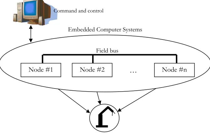
In industries, the use of computers cannot be ignored. It relates to a quality control, data acquisition for various management levels, etc. Computers control almost each machine and most computers are usually also connected via a certain network. Therefore, the computers can communicate to each other. We call it a distributed system. Figure 1.1 shows the configuration of a distributed system.
Due to increasing complexity of requirements and applied control algorithms, more and more processing power is needed. There is a trend in control industry to implement control systems as distributed, by delegating part of the work from central computer to intelligent controllers located near the drives. In this way system architecture becomes more modular and resilient to node and/or network failures. Networks provide means to download code into the boards, to change parameters online, identify devices on network, and transfer sensor, actuator and calculation data between nodes. To reduce wiring costs and associated problems, fieldbus architectures are often used.
Command and control
Embedded Computer Systems
Figure 1.1 Distributed systems with several nodes connected to a computer and a robot.
Node #1 Node #2 Node #n
Field bus
Fault-tolerance in real time distributed system using The CT Library
In a distributed system, several computers work in parallel and they can share their data via a fieldbus. Now, the problem becomes more and more complex, because the system consists of more computers instead of only one. Concurrency is the main idea. Here, this kind of system should be able to handle conditions such as deadlock, livelock, starvation, alarm shower, etc. These should be solved because their effect can be disastrous to the whole system.
In order to make a system robust to those kinds of condition, fault tolerance is needed. A system with fault tolerance can be considered as a robust system. It means the system is built less sensitive to some error. In general, there are two types of fault tolerance, i.e. hardware fault tolerance and software fault tolerance. This project will use software fault tolerance. For software fault tolerance, many techniques have been developed nowadays, but the goal is one, i.e. to build a reliable system. Unfortunately, there is no general fault tolerance technique for all problems; a problem is specific and its solution as well. Fault tolerance implemented in this project is concerned with switching from broken network to the available one. Therefore, when system detects, that the current network is broken; system replaces it with the available one.
The CSP (Communicating Sequential Process) is a notation for describing concurrent systems whose component processes interact with each other by communication (Hilderink et al., 2000). The CSP programming concept has been successfully implemented in Occam programming language, used so far mostly in a specific kind of processors known as transputers (Welch et al., 1993).
This project will use the Communicating Thread (CT) library made by Hilderink (Hilderink et al., 2000). The CT library implements occam-like processes, constructs and channels offering the API (Application Programmer Interface) of the CSP in popular programming languages. This library was developed after the transputer disappeared from the market. There are three libraries for CT, i.e. CT for Java (CTJ), CT for C (CTC) and CT for C++ (CTCPP). This thesis will use CTC.
To use the CT library on a specific processor, one should write hardware dependent parts, i.e. a context switch and a link driver. The context switch deals with how to handle transition from one thread to the next one. Every thread has its own context or state. When there is transition from one thread to another, this state should be saved to stack. This state will be restored from stack when the system jumps back to the thread.
In the CSP, processes communicate via channel. Channels between processes on one processor use built-in memory driver, while channels between processes on different processor use peripheral driver. These drivers are called link drivers (Hilderink et al., 2000). Essentially, link driver is object in which all hardware dependent code needed for proper operation of channel is encapsulated. This concept of separating hardware dependent and independent part came from (Hilderink et al., 2000). With this concept, if one wants to run the same program on different processor or to use different peripherals, only changes are needed in the hardware dependent part of context switch and/or link drivers, leaving the rest of the code intact. This makes the link driver concept very suitable for implementing the CT library in a distributed system. Figure 1.2 shows this diagram.
Hany Ferdinando
specific ID for each message, in other words the addressing is message based instead of location based.
Figure 1.2 Separation between hardware dependent part and hardware independent part (Hilderink et al., 2000)
The SPORT is a point-to-point communication link. Various serial communication protocols, like RS-232, can be based on SPORT links.
The fault tolerance implemented in this project deals with handling communication link failure. Therefore, when the system detects that the current communication link failed, that link will be replaced with the available one. The system always uses the available communication link with the highest priority. If the higher priority link is recovered, the system will switch back to this link.
1.2 Goal and Constraint
The goal of this project is to implement fault tolerance in a distributed system using the CT library. The link driver concept will be implemented for the CAN bus and the SPORT.
For there are many methods in the software fault tolerance, this project chose to implement fault tolerance to handle the broken link. In this idea, every node will have two communication links. If the primary link fails, the system communication will be transferred automatically to the alternative one. The CAN bus will be the primary link, while the SPORT will be the alternative one. The system will use two ADSP-21992 EZ-KIT LITE boards from Analog Devices. Other important constraint is that this thesis will use a simple transmitted data instead of data in structure.
Fault-tolerance in real time distributed system using The CT Library
1.3 Outline of the report
Chapter 2 carries out the background to implement this project. Fault tolerance part explains the difference between fault, error and failure. It includes the role of fault tolerance and method to implement it. The overview of a distributed system is also explained here. This project uses the ROPES (Rapid Object-oriented Process of Embedded System) software development approach. A brief discussion about ROPES is found here. This chapter discusses the CT Library, the heart of this project. The discussion emphasizes on the link driver and context switch concept. The hardware part such as the ADSP-21992, its communication link (CAN and SPORT) and the plant close this chapter.
Chapter 3 explains about the software and hardware design in this project. Especially, the design of the hardware dependent part, i.e. the link driver and the context switch for this project, are discussed here. A brief overview of the hardware part finishes this chapter.
Chapter 4 brings the design into implementation. The motivation behind several implementations will be explained here. Detailed information about dedicated link drivers for the ADSP-21992 is found here. It includes the implementation of fault tolerance in the Remote Link Driver class.
All experiments are presented in chapter 5.
Chapter 6 closes this discussion with conclusions from this project. Several recommendations for the next phase of this project are also presented here.
Chapter 2
Background
2.1 Fault tolerance – general overview
Fault tolerance is an approach by which the reliability of a computer system can be increased (Jalote, 1994). Fault tolerance itself is not a new area. There are many algorithms developed in order to get a better approach. Generally, fault tolerance consists of two main areas, i.e. the hardware and the software fault-tolerance.
Fault tolerance is a part of a larger set called dependability of a computer system. The development of a dependable computing system calls for the combined utilization of a set of four techniques: fault prevention, fault tolerance, fault removal and fault forecasting (Avizienis et al.).
2.1.1 Fault – error – failure
To deal with fault tolerance, one needs to understand concepts of fault, error and failure. Sometimes, it is difficult to distinguish them. According to (Jalote, 1994), fault will generate error and an error is that part of the system that is liable to lead to subsequent failure. A failure of the system occurs when the behavior of the system deviates from that required by its specifications. In (Avizienis et al.), fault is the adjudged or hypothesized cause of an error (a fault is active when it produces an error, otherwise it is dormant), an error is that part of the system state that may cause a subsequent failure (a failure occurs when an error reaches the service interface and alters the service). A system failure is an event that occurs when the delivered service deviates from the correct service. Figure 2.1 shows this relation in a diagram.
Figure 2.1 the fundamental chain of threats to dependability (Avizienis et al.)
Though a fault has the potential for generating errors, it may not generate any error during the period of observation. In other words, the presence of fault does not ensure that an error will occur. The reverse; however is not true (Jalote, 1994). When there is an error, fault(s) must have occurred prior to error. For the source of the failure comes from fault, one should take care this fault.
Fault-tolerance in real time distributed system using The CT Library
2.1.2 Role of Fault Tolerance
Fault tolerance comes from the fact that fault prevention is not enough. The fault prevention approach is achieved by eliminating as many faults as possible before the system is put in regular use (Jalote, 1994). However, it is very difficult to guarantee that fault prevention has eliminated all faults in a system. This is the reason why fault tolerance is important. Therefore, fault prevention will do its part during design phase, while fault tolerance will do its part in the operational phase.
Fault tolerance will not eliminate faults in a system, but will handle it in order to avoid generating error. Fault tolerance is intended to preserve the delivery of correct service in the presence of active faults (Avizienis et al.) or to avoid system failure, even if faults are present (Jalote, 1994).
Systems with a fault tolerant facility will have redundant components inside the system, because the redundancy is the key to supporting fault tolerance. The redundant component will not play its role when there is no fault. Unfortunately, a system, as a whole, cannot be made fault tolerant against its own failure (Jalote, 1994). A system can be made fault tolerant to other system’s failure. This is the reason why in a fault tolerant system, there will be redundant components. Therefore, these redundant components are such a small sub-system against other sub-system’s failure. There are two types of redundancy, i.e. hardware redundancy and software redundancy. All are used in the implementation of fault tolerance in a distributed system (Jalote, 1994).
2.1.3 Fault tolerance Method
Nowadays, no general technique can be proposed to add fault tolerance in a system. It depends on the requirements of the application (Torres-Pomales, 2000). Fault tolerance can be implemented using two approaches, i.e. hardware and software fault tolerance.
The Hardware fault tolerance relates to an electrical characteristic of the system, e.g. voltage level, sink-source current. The component factories, especially for semiconductor components, implement this kind of fault tolerance. Once a chip is on the market, there is no possibility to repair it if there is an error. That is why, the hardware fault tolerance is also important. However, the hardware fault tolerance is not the focus of this project.
The Software fault tolerance deals with software design. A programmer will add some redundant parts inside the software to handle faults and prevent failures. The development of object-oriented programming is very helpful in this technique.
In providing a fault tolerance, four phases can be identified: error detection, damage confinement, error recovery, and fault treatment and continued system service (Jalote, 1994). The error detection is important since this indicates the presence of fault (and failure). Any damage caused by that error will be identified by in damage confinement phase, and then error recovery is done. After recovering from the error, fault treatment will localize the erroneous component from the operation and continue system service.
Hany Ferdinando
with a single piece of software by adding a mechanism into the design to detect and handle the errors. For multi-version technique, fault tolerance uses several different versions (or variants) of the software with an assumption that error from different version of software will be different as well. For detail discussion about software fault tolerance, see (Torres-Pomales, 2000).
2.2 Distributed Systems
(Jalote, 1994) categorized two views on a distributed system namely as a physical model or a logical model. The former is defined by the physical component of the system, but the later is defined from processing or computation point of view. Both are important.
2.2.1 Physical Model
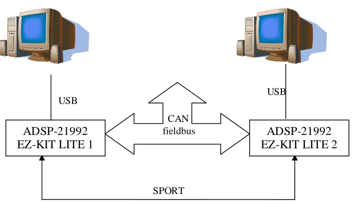
In the physical model (or application model), a system consists of several computers (called nodes) in different places. They are connected through some communication network.
The way in which the different links are connected to different nodes is called a network topology. There are many network topologies, e.g. fully connected, star, tree, bus. The most popular one is the bus topology. For the bus topology, there are many protocols available now, e.g. the CAN bus, the I2C, etc.
SPORT USB
CAN fieldbus
USB
ADSP-21992 EZ-KIT LITE 1
ADSP-21992 EZ-KIT LITE 2
Fault-tolerance in real time distributed system using The CT Library
2.2.2 Logical Model
From the application point of view, distributed processes can be implemented in a single computer, thus without a communication network. This model consists of concurrently executing processes that co-operate with each other to perform some task.
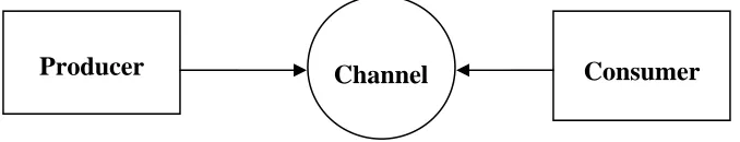
At a logical model (or an architecture model), a distributed system considers as consisting of finite set of processes and channels between the processes. Channels represent the logical connection between the processes. Two processes will communicate to each other through this channel. There are two kinds of channels, i.e. synchronous and asynchronous channels. In the synchronous channel, if one process sends something to other process, it must wait until the receiver acknowledges receipt of that data. In addition, a receiver must wait until the transmitter sends something. The Asynchronous channel omits this kind of synchronization, because the channel is buffered.
Producer Channel Consumer
Figure 2.3 Logical model of the simple user application based on process/channel paradigm
2.3 ROPES development cycle
To develop a system, one has to do some iterative process. In case of an Embedded Systems, this can be ROPES (Rapid Object-oriented Process of Embedded System) (Douglass, 2003). This approach is used in many real-time and embedded development environments. This iterative process is from simple to complex, from general to specific.
Hany Ferdinando
Figure 2.4 shows this iterative approach. Each cycle starts with analysis followed subsequently by design, implementation and testing. The result of one cycle is a prototype.
2.4 The CT Library
The CT library consists of hardware dependent and hardware independent parts. A user needs to write his own hardware dependent parts when these parts are not available yet, usually when a user uses a new processor. The hardware dependent parts include context switch (it depends on the processor architecture) and link driver (it depends on the peripherals on the processor).
2.4.1 Context Switch
Running parallel programs in a single ordinary processor is tricky. It must use some mechanism to share the CPU execution time among parallel software units of execution. Indeed, the execution inside the processor is sequential, but from outside point of view, all processes look like they run in parallel. The problem is how to move from one process to another. The answer lies in the context switch. That is why this part is very important in the CT library.
All parallel processes will be considered as threads. All threads will wait in the ready queue before running. Each thread has a priority and its own stack. It is the dispatcher’s responsibility to manage those threads: to decide which thread from ready queue will run next, and to perform a context switch from currently executing thread to the next one.
The dispatcher will compare the priority of the current thread to that of the thread from the top of the sorted ready queue. If the priority of current thread is higher than or the same as that of in the ready queue, there is no context switching. Otherwise, context switching will occur.
If there is a context switch, all necessary information on the current thread is saved to a stack and all necessary information of the next thread is loaded. Part of the code that deals with a stack and a memory is most often hardware specific. This is the reason why the user needs to know how to implement it in a specific processor.
2.4.2 Link Driver
There are two types of channels in the CT library: channels with and channels without a link driver. A channel without a link driver is a simple entity that connects processes internally in a single processor. This type of channel can be viewed as a channel with built-in local memory link driver handling either a rendezvous or buffered communication. On the other hand, a channel with a link driver is a special channel, because processes use hardware dependent part of the processor, e.g. ADC, RS-232, etc. Therefore, channels in a single processor share memory and execution time; while in distributed system, channels share a peripheral driver (Hilderink et al., 2000).
Fault-tolerance in real time distributed system using The CT Library
acknowledge, that process is released. For buffered channel, a process does not wait for acknowledge because the data is received in buffers. When the receiver is ready, the data will be read.
Link drivers deal with hardware dependent parts of a program code. This hardware can be a communication link (such as RS-232, SPORT, SPI, CAN bus, USB, Firewire, etc.) or a peripheral device (such as Timer, PWM, ADC, DAC, etc.).
A process connected to a channel does not need to know whether that channel has a link driver or not. If that channel uses a link driver, then the read and write methods of that channel will be delegated to those of that link driver.
2.5 The CAN bus
The CAN bus was developed by Robert Bosch GmBH in 1980s. Originally, the CAN bus was developed for automobile industry, but now the application become wider and wider in industries.
The CAN bus is classified as CDMA/CD (Carrier Detect Multiple Access with Collision Detection). It means, whenever one node wants to use the bus, it needs to detect first if the bus is occupied or not. The detection procedure uses an arbitration algorithm. This will be explained later. More details are presented in (Robert Bosch GmBH, 1991).
The CAN bus uses content based addressing instead of location based addressing. Thus in CAN, message ID (identifier) does not contain address of receiver node, but every node knows IDs of messages it wants to receive. Therefore, several nodes can receive data with the same ID. This will make the system simpler since if several nodes need data from the same type of sensor, the system does not need to install one sensor for each node. Beside, this makes system more flexible. To add a receiver-type node, the system does not need to be re-programmed anymore. The node transmitting the lowest number of ID (this means that node has highest priority) will get the bus. The other nodes wait until the bus is free again (bus idle state).
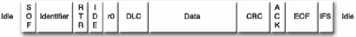
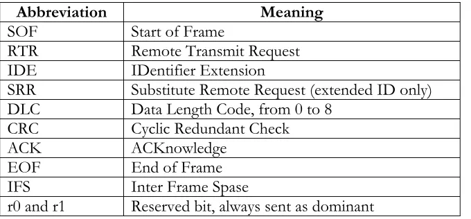
There are two CAN bus frame formats, namely 2.0 A and 2.0 B. The difference between them is in length of their ID. The former uses an 11-bit ID, while the later uses a 29-bit ID. The CAN bus version 2.0B is extended mode of the 2.0A. Therefore, a node with 2.0B, can detect IDs from 2.0A, but not vice versa. For this reason, there are two version of the 2.0 B format, i.e. a passive and an active one. The passive means the node only acts as a receiver, while the active acts as a transceiver. Figure 2.5a shows the CAN frame format (this is CAN 2.0A). CAN 2.0B is different from 2.0A, figure 2.5b and 2.5c show this difference.
Figure 2.5a the standard CAN frame format (CAN in Automation, 2003)
Hany Ferdinando
arbitration process. The arbitration begins with the start of a frame. A node can send start of frame signal (SOF on Figures 2.5a-c) only when the bus is idle, otherwise, that node must wait. Table 2.1 provides explanation of several abbreviation used in figure 2.5.
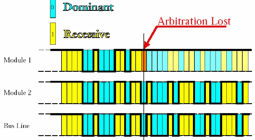
Transmitting of SOF is followed by a message ID. While transmitting their message ID, nodes have to monitor the bus level also. If the bus level and their transmitted level are different, then those nodes have lost arbitration and should stop transmitting their ID. This is the arbitration process (see figure 2.6). This operation enables the CAN bus to act as a multi-master bus that resolves bus access conflicts in a deterministic way.
Figure 2.5b CAN frame format for 2.0A (Robert Bosch GmBH, 1991)
Figure 2.5c CAN frame format for 2.0B (Robert Bosch GmBH, 1991)
Table 2.1 List of terminologies in figure 2.5
Abbreviation Meaning SOF Start of Frame
RTR Remote Transmit Request
IDE IDentifier Extension
SRR Substitute Remote Request (extended ID only) DLC Data Length Code, from 0 to 8
CRC Cyclic Redundant Check ACK ACKnowledge EOF End of Frame
IFS Inter Frame Spase
r0 and r1 Reserved bit, always sent as dominant
To achieve design transparency and implementation flexibility, the CAN bus protocol has been subdivided into different layers:
Fault-tolerance in real time distributed system using The CT Library
This layer deals with an electrical characteristic of signal on the transmission media, and the transmission media itself. The transmission media can be a single wire, a twisted pair (shielded or unshielded), a fiber optic, etc.
• Transfer layer
The transfer layer consists of kernel of the CAN, a transfer protocol, bit timing procedure, control over CAN.
• Object layer
Tasks of this layer are message filtering, message and status handling. The message filtering is important to detect if the ID is important to that node or not, while message and status handling interpret a message and a status of the bus.
Figure 2.6 Arbitration process (Kvaser)
The CAN controller handles all CAN operation such as arbitration, error checking, framing, acknowledge signaling, error handling and fault confinement. The following text will explain each of these operations.
The five frames are data frame, remote frame, error frame, overload frame and interframe space. Since there are five types of frames in the CAN bus, a controller should choose which frame is appropriate for a given task. 1 bit (RTR) is used to distinguish data from a remote frame. If one node is busy and cannot receive more data, then an overload frame is sent. Inter Frame Space (IFS) is space between two frames.
Hany Ferdinando
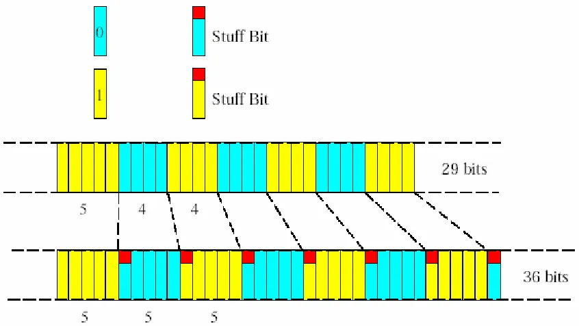
There are several error types in CAN, they are bit error, stuff error, CRC (Cyclic Redundancy Check) error and acknowledge error. The bit error actually happens on the arbitration process. The CAN uses bit stuffing in sending data. It means for five consecutive bits with the same value, one opposite bit will be inserted (see figure 2.7). Stuff error takes care of an error when this rule is violated. The CRC does the error checking. In this operation, a receiver node will calculate the CRC of all bits then compare it to CRC calculation from the transmitter. If they are different, that receiver will send an error frame to ask for retransmission.
To guarantee the CAN bus operation, a fault confinement algorithm is made. These algorithms deal with a transmitter and a receiver error counter. The value of this counter influences the behavior of that node. If the value is between 0 and 127, a node is in active error mode. For 128 to 255, a node is in passive error mode. When the value exceeds 255, a node is in bus off mode. (Robert Bosch GmBH, 1991) explain this in detail.
Figure 2.7 Bit stuffing in CAN bus (Kvaser)
2.6 The SPORT (Serial Port)
The SPORT stands for Serial Port. It is a general-purpose serial point-to-point link to transfer data from one processor to another. The heart of SPORT is the clock. The clock will control the data transfer between two nodes. It means the speed can be varied during sending the data. (Analog Device Inc., 2002a).
Fault-tolerance in real time distributed system using The CT Library
The SPORT operation enables data framing or not. This means that user can use a frame to indicate a group of data. SPORT can be used to emulate the serial RS-232 protocol. The ADSP-21992 EZ-KIT LITE boards even have RS-232 connector on board.
2.7 ADSP-21992
The ADSP-21992 (Analog Device Inc., 2002a) is a 16 bits fixed-point DSP processor from Analog Devices. This chip is developed from the ADSP-21990. The main difference is the addition of the CAN controller. The ADSP-21992 is a complete chip not only for DSP operation but also for a general-purpose controller. This chip is also equipped with DMA (direct memory access) controller. There are three buses inside this chip; they are PM (Program Memory) bus, DM (Data Memory) bus and DMA bus. Each bus consists of separate address and data bus.
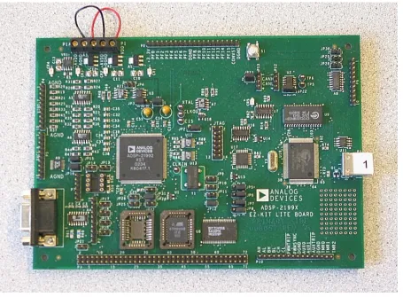
Figure 2.8 The ADSP-21992 EZ-KIT LITE boards
Hany Ferdinando
The ADSP-21992 comes with a development kit board called the ADSP-21992 EZ-KIT LITE. Figure 2.8 shows this development board. In normal operation, this evaluation board is driven by 16MHz for its operation clock (CCLK – Core CLK), derived from 32MHz clock generator. The peripheral clock (HCLK – Peripheral CLK) is always half of the operation clock. This information is very important since all timing for peripherals will be derived from HCLK. With software manipulation, the user can drive the ADSP-21992 chip on this board up to 160MHz as CCLK. Appendix A, section A.1.1 explains how to do this. There are two connectors for the CAN bus and a jumper to enable 120Ω resistor to terminate the network. With these two connectors, a user can daisy chain the board. The SPORT connectors will be used to connect this board to another board with SPORT facility.
2.7.1 CAN in the ADSP-21992 EZ-KIT LITE
The CAN controller in the ADSP-21992 organizes CAN buffer as 16 different mailboxes. A mailbox contains data buffer, the number of transmitted or received byte, message IDs and message filters. A user can configure each mailbox either as a transmitter or as a receiver.
Configuring the CAN controller means to set up the CAN speed, to configure direction of the mailboxes to transmit or to receive data and to set a value of filter mask for the receiver mailboxes. The maximum speed of the CAN bus is 1Mbps, but Analog Devices recommends using speed lower than 1Mbps (Analog Device Inc., 2002a).
Appendix A, section A.2 gives more detail on the CAN module in the ADSP-21992 and its initialization. After all initializations, one needs to know the performance of CAN module in the ADSP-21992, and appendix B showed the result of experiments designed to benchmark its performance.
The ADSP-21992 provides three interrupts for CAN, i.e. a transmitter mailbox interrupt, a receiver mailbox interrupt and a CAN global interrupt. They are peripheral interrupts mapped to user’s interrupt. Every successful transmitting message from the transmitter mailbox is followed by invoking a mailbox transmitter interrupt. When a receiver mailbox receives message well, the CAN controller will generate a mailbox receiver interrupt. The Global interrupt handles other events important for CAN operation. Appendix A, section A.2 gives some errata for chapter 13 of (Analog Device Inc., 2002a).
For the transmitter mailbox, a user should write all necessary data first before enabling it. Data here refer to message ID for CAN, the size of message and the data itself. When all data is ready, the transmitter can send it after enabling that mailbox. For every successful transmission, there will be a CAN transmitter interrupt (if this interrupt is enabled). This interrupt is only information that the message is transmitted well. This is not an indicator that a receiver mailbox has received that message. That signal means that the data arrived safely on the receiver’s side. This paradigm is very important. Therefore, a user cannot use this interrupt as an indicator that the target mailbox received that data well. A user can choose to overwrite the unread data or to protect those unread data. If choice is made to protect unread data, the user will lose the incoming data although the receiver’s side already received that data. The experiment presented in the Appendix B, on section B.2 illustrates this phenomenon.
Fault-tolerance in real time distributed system using The CT Library
find data length code, the data bytes and the message ID. Inside this Interrupt Service Routine (ISR), the interrupt signal should be cleared.
2.7.2 SPORT in the ADSP-21992 EZ-KIT LITE
The SPORT in the ADSP-21992 is clocked by either HCLK or an external source. The user can select this source. These are the features of SPORT in ADSP-21992 (Analog Device Inc., 2002a):
• Provides independent transmit and receive functions
• Transfers serial data words from three to sixteen bits in length, either MSB-first or LSB-first
• Double-buffers data (both receive and transmit functions have a data buffer register and a shift register), providing additional time to service the SPORT
• Internally generates serial clock and frame sync signals in a wide range of frequencies or accepts clock and frame sync input from an external source
• Performs interrupt-driven, single-word transfers to and from on-chip memory under DSP core control
• Provides Direct Memory Access transfer to and from memory under I/O processor control. DMA can be autobuffer-based (a repeated, identical range of transfers) or descriptor-based (individual or repeated ranges of transfers with differing DMA parameters).
• Executes DMA transfers to and from on-chip memory—the SPORT can automatically receive and transmit an entire block of data
• Permits chaining of DMA operations for multiple data blocks
• Has a multichannel mode for TDM interfaces—the SPORT can receive and transmit data selectively from channels of a time-division-multiplexed serial bitstream multiplexed into up to 128 channels—this mode can be useful as a network communication scheme for multiple processors
• Can operate with or without frame synchronization signals for each data word; with internally-generated or externally-generated frame signals; with active high or active low frame signals; and with either of two configurable pulse widths and frame signal timing
Hany Ferdinando
To do some basic configuration for the SPORT means to set the speed of the clock (derived from HCLK), to select between using external or internal clock source, to select using frame synchronization or not, and to set the number of bit sent via the SPORT. Chapter 8 of (Analog Device Inc., 2002a) gives detailed explanation about the SPORT in the ADSP-21992. (Analog Device Inc., 2002a) also writes that the maximum data transfer rate of the SPORT is half of the HCLK. For initialization procedure, see Appendix A, section A.3.
2.8 Hardware of the plant
A plant is used to demonstrate whether fault tolerance is working or not. The plant used is the LINIX. The LINIX is a DC motor with an inertia as load, a flexible transmission belt and a rotary encoder. The motor and the inertia load are connected with a belt. Since the focus of this project is on implementing fault tolerance mechanism in scope of the CT library communication subsystem, and not on the control design, a simple PID control law was used. The control loop is implemented as distributed using the CAN bus or alternatively, the SPORT link. After unplugging the CAN connection, the system should continue to work using the alternative SPORT connection. After the CAN is plugged-in again, this should be detected by software and the CAN should be automatically put back in a service. If now we disconnect the SPORT, the plant should again continue to work as though nothing is going on.
The system uses one-way configuration. On this configuration, there is only one data communication, from board 1 to board 2. Board 1 reads the reference signal and actual speed of the motor, calculates the difference between these signals and sends that to board 2. Board 2 calculates the PID control action and steers the motor.
Chapter 3
Software and Hardware Design
3.1 Context Switch
There are two approaches to implement a context switch, i.e. using an assembly language or using setjmp() and longjmp() C functions. Both have their own advantages and disadvantages.
Implementation using an assembly language is difficult, especially if a user is not familiar with the processor’s architecture. The main reason is that a user must decide on set of registers that need to be saved into a stack. This approach allows a context switch to happen during ISR execution.
On the other hand, the implementation using two functions setjmp() and longjmp() is easier than using assembly, because the compiler will translate those functions into assembly code and a user does not need to decide which registers should be saved into the stack. The compiler generates assembly code from C/C++ code in such a way that the set of the registers used in one C instruction is much larger then set of registers common to neighboring C instructions. Therefore, if the context switch can only happen between C instructions, only a small subset of registers is kept on stack. This idea is exploited by using setjmp()/longjmp() to implement a fast and absolutely portable context switches mechanism. However, this solution does not allow context switching to happen during the ISR, because interrupts can happen between any two-assembly instructions.
This project uses the second approach, i.e. using setjmp() and longjmp() functions. The reason is implementing a context switch as soon as possible is more needed than the way it handles the ISR. These two functions are already implemented in most of the C libraries (also in the C library for the ADSP-219x), therefore, a user will not really face incompatibilities if he changes the processor. Thus, the only instructions added in assembly are concerned with setting the initial stack pointer value for newly created process.
A user needs to know which register is used as a stack pointer register on that processor. For ADSP-21992, this register is the index register I4 (it will serve as stack pointer).
Fault-tolerance in real time distributed system using The CT Library
3.1.1 setjmp( ) function
Here is the description of the setjmp() function according to (Analog Device Inc., 2002c). The purpose of this function is saving all necessary parameters to a stack. This function saves the calling information in the jmp_buf argument. The effect of the call is to declare a run-time label that can be jumped to via a subsequent call to longjmp.
When setjmp is called, it immediately returns with a result of zero to indicate that the environment has been saved in the jmp_buf argument. If, at some later point, longjmp is called with the same jmp_buf argument, longjmp will restore the environment from the argument. The execution will then resume at the statement immediately following the corresponding call to setjmp. The effect is as if the call to setjmp has returned for a second time but this time the function will return a non-zero result.
The effect of calling longjmp will be undefined if the function that called setjmp has returned in the interim.
3.1.2 longjmp( ) fiuncton
Here is the description of the longjmp() function according to (Analog Device Inc., 2002c). The longjmp function causes the program to execute a second return from the place where setjmp (env) was called (with the same jmp_buf argument).
The longjmp function takes as its arguments a jump buffer that contains the context at the time of the original setjmp. It also takes an integer, return_val, which setjmp returns if return_val is non-zero. Otherwise, setjmp returns a one.
If env was not initialized through a previous call to setjmp or the function that called setjmp has since then returned, the behavior is undefined. In addition, automatic variables that are local to the original function calling setjmp, that do not have volatile-qualified type, and that have changed their value prior to the longjmp call, have indeterminate value.
Use setjmp()
function Use
longjmp() function
Figure 3.1 Timing diagram of context switch mechanism
Figure 3.1 shows the timing diagram of context switch mechanism. The grey box is only done first time new thread is scheduled.
Set I4 (SP) register to point to stack of newly created thread and start
execution of its run() method SP = Stack Pointer
Determine next
Process thread Save the context of currentProcess thread to jmp_buf Jump to the next Process thread
Start of
Hany Ferdinando
3.2 Embedded system requirements
Since resources in an embedded system are limited, the ISR should be able to direct itself efficiently to the appropriate location without wasting time. Several CAN mailboxes will be used. They will serve as a transmitter, a receiver, an acknowledge transmitter and an acknowledge receiver. It also needs two additional mailboxes to detect link failure. In case of the SPORT, there will be simple protocol to distinguish data, acknowledge and link test.
The ISR should last as minimal amount of time as possible. Calling any potentially blocking synchronization primitive (like rendezvous channels communication) is not permitted from inside of the ISR.
3.3 Extension of the Link Driver concept
Hilderink proposed a link driver as a hardware dependent part of a processor (Hilderink et al., 2000). The idea behind this is to encapsulate hardware related operations into certain parts of the software. This will facilitate the use of the same program in different processors or with different peripheral hardware. What needs to be done in such a case is only changing the link drivers. No changes are needed in user’s application. Therefore, it is easy to move an established program from one processor to other processor.
Figure 3.2 shows link driver concept. It starts from a concept of a channel. All processes communicate to each other via channel only, through read and write functions. Inside each channel, there is a link driver. The link driver encapsulates hardware dependent part of code used inside a channel. Processes are independent from the hardware. Therefore, in figure 3.2 there is a dashed line to separate hardware independent part from hardware dependent part.
Fault-tolerance in real time distributed system using The CT Library
For peripherals handling communication (CAN, SPORT) this concept has been extended, as shown on Figure 3.3 (Orlic et al., 2003). The motivation to extend Hilderink’s idea is to implement a mechanism for addressing channels in a distributed system, and to divide the part of the LinkDriver implementing higher communication OSI layers from the part implementing lower level hardware and fieldbus protocol specific parts. The RemoteLinkDriver class will be derived from the LinkDriver class, thus inheriting the interface of the Link Driver and ability to be plugged-in the channel.
Channel Producer
Link driver
CAN Device
Driver
SPORT Device
Driver
SPORT Device
Driver
ADSP 21992 CAN
Figure 3.3 Modified concept of implementing link and device drivers (Orlic et al., 2003)
Specific for communication link driver, there will be the Network Device Driver (NDD). All communication link drivers (CAN Device Driver and SPORT Device Driver on Figure 3.3) should be derived from this abstract class.
Besides, this modification aims at obtaining flexibility and fault tolerance in using the available communication peripherals. This means the communication link can be changed (for example, in case of network failure or to implement some traffic congestion control) during the operation, without shutting down the system. Therefore, if there is an alternative route for a message, switching to that route is done transparent to processes using the channel.
The RemoteLinkDriver class saves the available communication link driver inside a look up table. This class also holds a method to switch from a failed communication link to one that is available or to switch from the currently used to recovered higher priority link.
Classes for peripherals, such as ADC, DAC, PWM, Encoder Interface Unit and flag I/O., are derived from the LinkDriver class directly.
Hany Ferdinando
board. In this project, two different types of Network Device Drivers are implemented: one dedicated to managing the CAN fieldbus and the other controlling the SPORT. Requests of Producer/Consumer process to write/read on a channel will be delegated to the Remote Link Driver object, which will divide/assembly messages into/from packets and use the services of one of available NDDs to transmit/receive packets. A channel will never know which NDD is used. For the other peripheral device, its link driver will be called from the LinkDriver class. It is strongly advised that users never accesses the hardware dependent part outside the LinkDriver class. Figure 3.4 shows the class structure implemented in this project.
+read() : void +write() : void +isExternal() : void +isInputReady() : void +isOutputReady() : void +constructor() : LinkDriver +destructor() : void
LinkDriver
-buffer : signed int -bufferSize : unsigned int
+read() : void +write() : void +isExternal() : void +isInputReady() : void +isOutputReady() : void +constructor() : RemoteLinkDriver +destructor() : void
RemoteLinkDriver
-bAck : bool
+transmit() : void +receive() : void +init() : void
+constructor() : NetworkDeviceDriver +destructor() : void
NetworkDeviceDriver
+transmit() +receive() +init() +checkLink()
+constructor() : CANDeviceDriver +destructor() : void
CANDeviceDriver
+transmit() +receive() +init() +checkLink()
+constructor() : SPORTDeviceDriver +destructor() : void
SPORTDeviceDriver -End1 1 -End2 * -End3 1 -End4 *
+constructor() : DeviceDriver +destructor() : void
DeviceDriver
+constructor() : ADSPDeviceDriver +destructor() : void
+init() : void
ADSPDeviceDriver
+constructor() : ADCLinkDriver +destructor() : void +read() : void +isExternal() : bool +init() : void
ADCLinkDriver
+constructor() : EIULinkDriver +desctructor() : void +read() : void +isExternal() : bool +init() : void
EIULinkDriver
+constructor() : AuxPWMLinkDriver +destructor() : void
+write() : void +isExternal() : bool +init() : void
AuxPWMLinkDriver -End5 1 -End6 * -End7 1 -End8 * -End9 1 -End10 *
+init() : void +Timer2_IRQ() : void
«interface»
Timer
+init() : void +FIOA_IRQ() : void
«interface» DigitalFlag -End11 1 -End12 * -End13 1 -End14 *
Fault-tolerance in real time distributed system using The CT Library
Figure 3.5 Sequence diagram of transmit and receive process in the producer and consumer The address of each channel in the system is composed of two parts: a node identifier (nodeID) and channel identifier (channelID). A node identifier is used to route message to a destination node. Channel ID is a unique identifier of a channel in scope of its node. Together node ID and channel ID make a unique address. Such an address is independent of the communication link used. However, the way in which this address is actually used is specific to the fieldbus protocol used.
The SPORT is a point-to-point link and therefore address of the destination node is fixed in wires and need not be sent. Address of the channel has to be sent if multiple channels are intended to be used.
In the CAN bus, addressing is specific in a sense that it is content based. All mailboxes from all nodes in the system filter the identification bits (messageID) of every message on bus. A message will enter a mailbox if a messageID match the filter and there is free place in mailbox. Clearly, in case of the point-to-point channels, the most efficient solution is to incorporate the destination nodeID as part of messageID.
3.4 Description of complete transmit-receive process
This section explains the detail description of transmit-receive process between one producer (P) and one consumer (C) on a different processor. Figure 3.5 shows the sequence diagram of this process.
Producer Consumer
ISR releases consumer Read() Write()
ISR releases consumer Prepare the data Blocked,
wait for data
Write data to channel
Read data Blocked,
wait for ack. ISR releases
producer Read()
Send acknowledge Prepare the data
Write data to channel
Blocked, wait for data
Read data Write()
Blocked, wait for ack.
Send acknowledge ISR releases
Hany Ferdinando
O
this process is blocked by a semaphore.
or the acknowledge signal. Upon receiving this signal, the P
3.5 Fault Tolerance in the CT library
a distributed system, one needs to
ce built in this project relates to the communication link. Generally, several links
r not, one board (master) will send regular message to
ose, there will be a switch on the cable. Instead of plugging or
ed as soon as possible by the ther necessary information specific to this test case is that the default link is CAN bus and SPORT point-to-point link is used after detection of CAN bus failure. First, it is assumed that there is no failed link. P wants to write data to its channel. Because a link driver object is plugged-in to that channel, the execution of its operation is delegated to the Remote Link Driver’s write() operation. Inside this, the transmit method of default NDD (CAN Device Driver in this case) will be called to send this data packet by packet. Here, the data will be transmitted and the P is blocked (because P has to wait for acknowledge) from the C. The blocking mechanism is implemented using a semaphore.
At the other side, the C will read from its channel, but
This semaphore will be released in the ISR of receive mailbox interrupt. When data arrive at the CAN mailbox, an ISR is generated. The ISR will release the semaphore and the blocking process can continue. Here, the data is read and the C will send an acknowledge signal to the P to indicate that the data is already read.
At the other board, the P is waiting f
will be released and the next loop can run again. This is the normal operation without considering a network failure.
For there are many implementations of fault tolerance in
define what kind fault tolerance will be implemented here. This fault tolerance will be built in the CT framework.
The fault toleran
might be available to transport message between two nodes. In this study case, the main link is the CAN bus (this is the active link by default with the highest priority), while the alternative one is the SPORT. If something happened which makes the default link fail, the system will automatically replace it with the alternative one, without bothering a user’s application with exceptions and communication details.
To detect whether there is link failure o
the other board (slave). The slave will send back this signal to the master (echo). If within pre-defined time there is no echo received, the master knows that the communication link has failed. For the slave, if after sending an echo there is no more regular message, that node knows that the communications failed. The channel will not know whether there is changing from default to alternative link or not. In case the higher communication link is available again, the system will switch back to this link.
For demonstration purp
unplugging the cable, this switch will simulate breaking the cable.
When there is a network failure, the broken link should be replac
Fault-tolerance in real time distributed system using The CT Library
a link failure.
3.6 Hardw
implemented fault tolerance is working or not. The l hardware circuits are used to enable LINIX work
s a reference signal)
Figure 3.6 shows the sequence diagram used in the fault tolerance implementation. It also illustrates when there is
Figure 3.6 Sequence diagram of fault tolerance implementation
Master Slave
send regular data
send echo wait for echo
time out
time out
Receive ISR set the flag
Receive ISR set the flag Timer’s ISR clear the flag
The link is broken
replace the broken link
replace the broken link Timer’s ISR
are of the plant
A plant is used to demonstrate whether the plant used is the LINIX. Several additiona with the ADSP boards:
• PWM motor driver
• Potentiometer (a
• Power supply circuit
clear the flag send regular data
send echo wait for echo
time out
time o
ceive ISR set the flag Re
Receive ISR set the flag Timer’s ISR
time out
Hany Ferdinando
board to display if CAN and SPORT links are
Figure 3.7 shows the block diagram of the plant while figure 3.8 shows the complete additional hardware circuit used to enable 2 board. See figure 3.7, board 1 receives data from reference (set point) and encoder (present speed) then send synchronization
On figure 3.4, a Potentiometer (R6) acts as a reference signal. It will deliver a voltage from a M317, to the ADC unit of the ADSP-21992. When R6 is in maximum value, R5 should be adjusted to get 1 volt at ADC channel 1 output.
To control speed of the DC motor, one can control the voltage applied to that motor. In the polarity will change the direction of the motor. In order to generate a variable DC voltage from a digital system, the PWM approach is used. Usually, the current is not
ge by controlling one of the input pins with a PWM signal. The other pin is for the direction. The later pin is not used, since this project relates to speed control.
This additional circuit contains LEDs to indicate that the communication links are available. The green and yellow LED is for CAN and SPORT respectively. When the LED is on, the corresponding communication is available. Digital I/O flags of the ADSP-21992 control the LEDs.
• 2 LED indicators are used per each available.
ADSP-21992 EZ-KIT LITE
(1)
ADSP-21992 EZ-KIT LITE
(2) Ref. signal
En
c
o
d
e
r
PW
M
CAN bus
Figure 3.7 One-way configurations
LINIX works with the ADSP-2199
pulse to board 2 to steer the DC motor via PWM circuit using value from previous cycle. Board 1 calculates the difference between set point and the present speed then send the result to board 2. Board 2 upon receiving this data calculates controller action for the next cycle using PID controller.
3.6.1 Potentiometer
regulated power supply, L
3.6.2 H-bridge
addition, inverting
enough. For this purpose, an H-bridge is used. The H-bridge here is taken from the ARTY robot project (Engelen, 1999).
The H-bridge gets its name from the fact that the circuit forms the letter ‘H’. With this circuit, one can get a variable DC volta
Chapter 4
Implementation
4.1 Object-Oriented Programming in C
The C language does not support the Object-Oriented Programming. For this reason, Hilderink mimics the behavior of this kind of programming for C (Hilderink). It includes single inheritance, polymorphism, packages, interfacing, instance construction and instance destruction.
With this style, it is easy to manage the program. Another advantage is that a user can easily transfer such a C program to C++ and the other way around. But the program looks like more complex.
4.2 Context Switch Implementation
First, a simple context switching mechanism is made using setjmp/longjmp functionality but without the CT library. The code of this minimal kernel is in Appendix C section C.1.1. Then the context switching mechanism of the CT library is carefully examined and changes ar
in several functions based on the minimal-kernel example.
In the CTC, atomic sections are implemented using two fu Processor__enterAtomic() and Processor__exitAtomic()
Processor__exitAtomic() function, context switch is performed if needed. The heart of the context switch is saving and restoring context of threads to and from the stac
implementation of the context switch in the CT library means writing three methods:
• void Processor__startswitch(void)
• void Processor__stopswitch(void)
• void Processor__contextswitch(void)
Unfortunately, assembly language cannot be avoided because pointer to the stack of the new thread must be written into the I4 register (used as a stack pointer by the C compiler). There is no other way to access this register except using assembly language. Changes to those functions are described in Appendix C section C.1.2.
e made
nctions: . Inside
Fault-tolerance in real time distributed system using The CT Library
4.3 Peripheral LinkDriver Implementation
4.3.1. ADCLinkDriver
ADC stands for Analog to Digital Converter. It converts analog signal input and gives digital signal as its result. It means the only operation related to value of this part is to read it. Therefore, ADCLinkDriver will only have read operation. The write operation will throw an error exception if one calls it.
The ADSP-21992 has eight channels of 14-bit ADC. Actually, there are several modes of operation but for simplicity, only the mode (simultaneous sampling mode) related to this project will be implemented. This project also uses only one channel.
To initialize ADC in the ADSP-21992 means to choose the mode of operation and select the clock divider. These will be done by writing a value to ADCCTRL register. To know whether the conversion is finished or not, an interrupt can be used. The ADC interrupt is mapped on IPR3 register at bit 12 to 15, written in (Analog Device Inc., 2002a) as IPR3[15:12]. This interrupt can be used to synchronize ADC operations.
Here is the idea for the read() method in the ADCLinkDriver. First, user should give command to ADC to start to convert the analog signal then this process will be blocked until the ADC interrupt releases it. After releasing that signal, the read() method continues by reading the result. Listing 4.1 shows the read() method in the ADCLinkDriver.
Listing 4.1 ISR and read() method of the ADCLinkDriver
void ADCLinkDriver__read(ADCLinkDriver me, Object obj,unsigned size){ sysreg_write(sysreg_IOPG,ADC_Page); // set to ADC page io_space_write(ADC_SOFTCONVST, 1); // start conversion
// wait for end of conversion interrupt
Processor__enterAtomic(); // enter atomic section Semaphore__p(me->sem); // wait here Processor__exitAtomic(); // exit atomic section
sysreg_write(sysreg_IOPG,ADC_Page); // set to ADC page
*(me->buffer) = io_space_read(ADC_DATA1); // read data from ADC register buff. *(int*)obj = *(me->buffer); // put data to the output
}
void ADC0_IRQ(){ unsigned temp;
sysreg_write(sysreg_IOPG, ADC_Page); // set to ADC page io_space_write(ADC_STAT,0x0100); // clear the interrupt
Semaphore__v(semADC); // release the reader
}
Hany Ferdinando
4.3.2 AuxPWMLinkDriver
PWM stands for Pulse Width Modulation. The idea is to produce variable DC voltage by varying the duty cycle of the square wave signal and keep the frequency constant.
from 0-100%. Indeed, the value of this duty cycle can be read, but the main is to set this duty cycle. This means PWM only has write opera ADCLinkDriver, the read operation will throw an error exception if one calls it.
This project only uses one of two channels. Therefore, th with one channel only. There is no interrupt used for t
consists of setting the operation frequency. In this operation, there is no synchronization as well.
Here is the idea for write() method in the AuxPWMLinkDriver. After writing a value to to perform the context switch if needed. In the CT library this can be done by explicitly calling pair of functions used to enter
MLinkDriver__write(AuxPWMLinkDriver me, Object obj, unsigned size){
= (unsigned)(*(me->buffer)); // write the value to temp sysreg_write(sysreg_IOPG,Aux_PWM_Page); // set to AuxPWM page
io_space_write(AUX_CHA0,temp); // write the value to register
ter atomic section
Processor__exitAtomic(); // exit atomic section, will allow
means the
num e ounted. To generate this constant time
duration, the EIU Loop Timer will be helpful. Beside, this can also generate an interrupt.
The fo t and at every interrupt the user can
read h nd store it into global variable of
initial experiment, the time duration is 1ms. This is long enough for low speed rotation. For time duration less than 1ms, the encoder output gives unstable value at low speed. The EIU Loop Timer interrupt is mapped on IPR3[3:0].
Duty cycle is varied operation for PWM tion. Opposite to
e AuxPWMLinkDriver will also deal his PWM and the initialization only
Auxiliary PWM register, control should be given to the dispatcher
and exit atomic section. Listing 4.2 shows this function.
Listing 4.2 write() method of the AuxPWMLinkDriver.
void AuxPW
unsigned temp; // declare temp variable
// only to change duty cycle, no lock and unlock mechanism needed
me->buffer = obj; // get the value
temp
Processor__enterAtomic(); // en
// context switch to happen here
}
4.3.3 EIULinkDriver
EIU stands for Encoder Interface Unit. This peripheral accepts pulses as input from an encoder and delivers the number of count from its counter. From this, it is clear that the EIU has a read operation only. Similar to ADCLinkDriver, the write operation will throw an error exception if one calls it.
The EIU in the ADSP-21992 is used to estimate the speed of the motor shaft. This b r of pulses in certain time duration should be c
re re, there will be a constant interval for this interrup t e number of pulses within that time duration a
EIULinkDriver. After reading that value, this interrupt will reset the value inside the quadrature counter, and the incremental counter will start from zero again.
Fault-tolerance in real time distributed system using The CT Library
er because for every EIU ed to a buffer and read() method can read it directly.
kDriver. Since there is no synchronization, after
e to the output
O); // store value to buffer
lementation
he parent class write nfortunately, only
Figure 4.1 Class diagram of communication link driver EIULinkDriver use no synchronization to read the quadrature count Loop Timer, the value of quadrature counter has already been stor
Here is the idea of read method in the EIULin
reading quadrature counter from certain buffer, control should be given to the dispatcher to perform the context switch if needed. Listing 4.3 shows the write() function of the EIULinkDriver.
Listing 4.3 ISR and write() method of the EIULinkDriver
void EIULinkDriver__read(EIULinkDriver me, Object obj,unsigned size){ *(me->buffer) = encoder; // read from buffer
*(int*)obj = *(me->buffer); // put the valu
Processor__enterAtomic(); // enter atomic section Processor__exitAtomic(); // exit atomic section }
void EIU0_Timer(){
sysreg_write(sysreg_IOPG, EIU0_Page); // set to EIU page encoder = (unsigned)io_space_read(EIU0_CNT_L
io_space_write(EIU0_STAT,0x0021); // clear the interrupt
io_space_write(EIU0_CNT_HI,0x0000); // reset the EIU counter high io_space_write(EIU0_CNT_LO,0x0000); // reset the EIU counter low }
4.4 Communication LinkDriver Imp
The RemoteLinkDriver class will be derived from the LinkDriver class. Since in t there are five undefined methods, a user should down those methods. U read, write and isExternal methods will be used.
+r +w +is
+isInputReady() : void +isOutputReady() : void
ead() : void rite() : void External() : void
+constructor() : LinkDriver +destructor() : void -bu
-b
ffer : signed int ufferSize : unsigned int
LinkDriver
+read() : void +write() : void +isExternal() : void +isInputReady() : vo di +isOutputReady() : void +constructor() : RemoteLinkDriver +destructor() : void
-bAck : bool
RemoteLinkDriver
+transmit() : void +receive() : void +init() : void
+constructor() : NetworkDeviceDriver +destructor() : void
NetworkDeviceDriver
+transmit()
+checkLink()
+constructor() : CANDeviceDriver +receive()
+init()
+destructor() : void
CANDeviceDriver
+transmit() SPORTDeviceDriver -End1 1 -End2 +receive() +init() * +checkLink()
+constructor() : SPORTDeviceDriver +destructor() : void
-End3 1
Hany Ferdinando
eripheral, an additional class is derived from the abstract NetworkDeviceDriver class. This abstract class is used to define an interface common to all
ever access hardware or register
out inside nk failures and
nd ost to the least
ra the system
k, e.g. k, unplugged link, etc.
received, the acknowledge flag will be set.
as two special methods, i.e. the handleLinkFailure and the
lable or not. Special for the communication p
fieldbus protocols and board specific Network Device Driver objects. It has four methods inside, i.e. transmit, receive, init (for initialization) and checkLink (for fault tolerance prupose). Figure 4.1 shows class diagram for the implementation of communication link driver. Actually, this is the upper part of figure 3.3.
4.4.1 Remote Link Driver
The RemoteLinkDriver will encapsulate all general-purpose communication operations. It means if one process uses its channel to send or to receive data, write or read methods of the RemoteLinkDriver will do this.
The RemoteLinkDriver consists of three methods, i.e. read, write and isExternal method. The isExternal method only returns a TRUE value. The read and write methods will use the available link with the highest priority in the system. Those methods n
directly but use the NDD’s functionality instead.
With this approach, it is possible to switch from one communication link to the other with bothering its operation. The RemoteLinkDriver uses only communication links available an array of a structured data. This structure should be made such that handling li
be one e ly. Th elem the m ha ling link recovery can d asi e ents are sorted from
important. From this idea, one