EURASIP Journal on Advances
in Signal Processing
Wanget al. EURASIP Journal on Advances in Signal Processing (2016) 2016:115
DOI 10.1186/s13634-016-0416-1
R E S E A R C H
Open Access
Range cell migration correction analysis of
one-step and two-step motion compensation
for millimeter-wave airborne SAR imaging
Guanyong Wang
1,2, Lei Zhang
1*, Jun Li
2and Qingrong Hu
2Abstract
Conventional two-step motion compensation (MOCO) method is widely adapted for airborne synthetic aperture radar (SAR) imaging due to its conciseness combining with the SAR focusing procedure. For two-step MOCO, range-independent compensation is processed before range cell migration correction (RCMC), and the range-dependent phase correction is implemented after RCMC. However, the accuracy of RCMC would be seriously decreased by the residual range-dependent phase, which is a fatal problem for high-resolution millimeter-wave (MMW) SAR imaging. In this paper, an extensive investigation on the RCMC accuracy is provided by establishing an accurate formula
expression between the range cell migration error and the residual range-dependent phase error. One-step MOCO-based SAR imaging algorithm is investigated by compensating the range-dependent motion error before RCMC, so the presence of range cell migration error would be significantly suppressed. What is more, a modified azimuth match filtering (AMF) function is given by precise topography and aperture-dependent motion compensation (PTA) method to overcome the residual azimuth-dependent phase error in the azimuth compression stage. Both simulated and real-measured MMW SAR data sets are used to validate the analysis for high-resolution airborne SAR imaging.
Keywords: Synthetic aperture radar (SAR), Motion compensation (MOCO), Millimeter-wave (MMW), One-step MOCO
1 Introduction
Motion compensation (MOCO) [1–4] is a crucial operat-ing step for airborne synthetic aperture radar (SAR) [5–7] imaging because the non-ideal movement deviates the radar platform from the predetermined flight trajectory. More importantly, for high-resolution millimeter-wave (MMW) [8] SAR systems, imaging performance is more sensitive to the envelope and phase of motion errors, so a precise MOCO is essential with the availability of high-precision inertial navigation system (INS) mea-surement. An efficient two-step MOCO algorithm [4] is proposed by Moreira and Huang, combining with chirp scaling algorithm (CSA) [9, 10] for airborne SAR imaging. This method is divided into range-independent com-pensation step and range-dependent comcom-pensation step,
*Correspondence: [email protected]
1National Lab of Radar Signal Processing and the Collaborative Innovation Center of Information Sensing and Understanding, Xidian University, Xi’an 710071, People’s Republic of China
Full list of author information is available at the end of the article
while the first step is processed to the range compressed data and the second step is processed after range cell migration correction (RCMC). The problem of con-ventional two-step MOCO processing is also obvious. The residual range-dependent motion error remained after the first step seriously decreases the accuracy of RCMC in two-dimensional wavenumber domain, which presents as a curving range cell migration (RCM) range profile in two-dimensional time domain, and destroys the performance of azimuth pulse compres-sion. Reference [11] describes the problem above for Omega-k algorithm [12, 13]. In their work, a one-step MOCO method is proposed, but the detailed analysis of the RCMC error is not given. Besides, the original MOCO methods only take range-dependent motion error into account, and the residual azimuth-dependent motion error should also be considered, which is non-ignorable for high-resolution airborne MMW SAR imaging with wide swath. The existed azimuth-dependent MOCO algorithms [14–18] could precisely compensate
the azimuth-dependent motion error and modify the azimuth matched filtering function in order to eliminate the influence of azimuth-variant motion error.
Based on the signal model in [3], we investigate the cause of RCMC error as well as its definite expres-sion deduction for MMW SAR system in this paper. A background assumption is confirmed that the trajectory information is accurately recorded by the INS and the whole motion compensation procedure is processed with-out autofocus step. The one-step MOCO-based imaging algorithm is investigated, which compensates range-dependent motion error before RCMC in order to sup-press the residual envelope and phase error of RCM range profile. Moreover, according to the analytical expression of the residual spatial variant error, an accurate azimuth match filtering (AMF) function is modified by precise topography- and aperture-dependent motion compensa-tion (PTA) [17], which compensates the residual azimuth-dependent motion errors remained by RCMC. In this paper, the conventional two-step MOCO-based imag-ing algorithm is introduced for comparison, theoretical analysis to the superiority of one-step MOCO would be adequately verified by simulated and real-measured data experiments.
The whole paper is organized as follows: Section 2 gives the signal and geometry model of the SAR imaging, RCMC accuracy respect to the residual range-dependent error is analyzed as well, and flowcharts of one-step and two-step MOCO-based SAR imaging algorithms are then given for comparison. In Section 3, RCMC error compar-ison between one-step and two-step MOCO is discussed, and computational burden of both methods is also ana-lyzed in detail. In Section 4, extensive experimental results are given with both simulated and real measured MMW airborne SAR data. Conclusions are given in the last section.
2 One-step MOCO-based SAR imaging algorithm
2.1 SAR imaging and RCMC error analysis
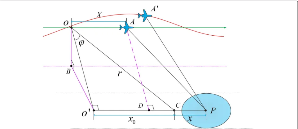
The squinted SAR geometry is given in Fig. 1. In the model above, the SAR sensor travels along a straight-line flight path with a constant velocityvin ideal conditions, and the synthetic aperture length is L. SymbolO stands for the original point of SAR sensor. The ideal linear trajectory is defined asX-axis corresponding to the azimuth direction, point A denotes the ideal position of platform. During the data acquisition, the radar beam illuminates at squint angleϕ, symbolCdenotes the scene center, andr repre-sents the range fromCto radar at squint angleϕ. SymbolP stands for the target located on the scene center lineOC, which is parallel to the trajectory. The distance between targetPand scene centerCis given byx, and the distance betweenOandCis given byx0. The instantaneous range
from targetPto the radar in the conical coordinate system [19] is given by:
whereX= vtmdenotes the instantaneous azimuth coor-dinate of antenna phase center at slow time tm. The expression of echo signal from targetPis given by:
S(τ,X)=εp·rect
Wanget al. EURASIP Journal on Advances in Signal Processing (2016) 2016:115 Page 3 of 11
Fig. 1Geometric model of squint SAR imaging
S(Kr,X) =
where Kr represents the range wavenumber spectrum with Kr = Krc+ Kr and Krc = 4πfc/c is the range wavenumber center withKr ∈
−2παTp/c, 2παTp/c
. Then, applying the azimuth FT to (4) with respect toX, the impact ofRE to the stationary phase point could be ignored for simplifying the analysis formula. The expres-sion of signal in two-dimenexpres-sional wavenumber domain is given by [3]:
whereKx represents the azimuth wavenumber spectrum andX∗denotes the ideal stationary phase point. The first phase term of (5) is expressed by a Taylor expansion with respect toKr = Kr −Krcaround Kr = 0, so (5) is
where the second term of (7) represents the range cell migration and the third term represents the second-order coupling phase. One may multiply both sides of Eq. (7) by HRCMC(Kx,Kr)andHSORC(Kx,Kr)to perform the RCMC and second-order range compression (SORC).
HRCMC(Kx,Kr)=exp
The expression of signal in two-dimensional wavenum-ber domain processed by RCMC and SORC is given as follows:
where the second term of (10) is shown in (11), which is considered the residual motion error phase in two-dimension wavenumber domain, decreasing the accuracy of RCMC seriously.
(Kr,Kx)=exp−jKrRE
X∗ (11)
is expressed as follows, remaining the constant term and
Ignoring the impact to the stationary phase point made byRE(X∗), we apply azimuth inverse Fourier transform
where the stationary phase pointKx∗is given by:
Kx∗≈ −Krc
X−rsinϕ−x
(cosϕ·r)2+(X−x−rsinϕ)2 (15) Substituting (15) into (12) with replacement ofKxbyKx∗ and orderingX−x = 0 for simply analyzing, the resid-ual motion error in azimuth time and range wavenumber domain is given by:
RE(X)=RE+
rsinϕ Krccos2ϕ ·
∂RE
∂X ·Kr (16)
Substituting (16) into (14), the expression of signal is translated to the following equation:
S(Kr,X)= exp
where the second term of (17) is the RCMC error with respect to the residual motion errorRE. This phase term is expressed as a series ofKr, so the phase and envelope component would be distinguished where
ϑ0=KrcRE (18)
It is worthy to note thatϑ0represents the phase com-ponent of RCMC error andϑ1denotes the envelope error of RCMC, which seriously destroys the imaging perfor-mance.ϑ2is the second-order term, which slightly reflects the focusing performance in range, and the effect could be ignored in most cases.
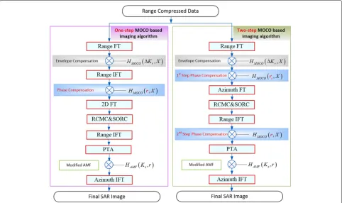
2.2 Flowcharts of one-step and two-step MOCO-based imaging algorithms
As shown in Fig. 2, a flowchart of the one-step MOCO-based imaging algorithm is given in this subsection, while the conventional two-step MOCO-based imaging algo-rithm is also given for comparison. It is here needed to explain that the flowchart is displayed in such form for the purpose of distinguishing the procedure of the one-step MOCO and two-step MOCO more legible. We introduce PTA for azimuth-variant MOCO in order to eliminate the influence caused by other residual special-dependent errors. In a one-step procedure, bulk envelope compensation is processed in range wavenumber domain by multiplyingHMOCO(Kr,X)to the range compressed data. The envelope compensation function is expressed as:
HMOCO(Kr,X)=exp
−jRr(rs) Kr (21)
whereRr denotes the slant range projection of motion error, which is with respect to slant range r and would be expressed in (26). Then, the range-dependent motion error is compensated in range time domain by multiplying HMOCO(r,X), where
The compensated data is then transformed into two-dimensional wavenumber domain, and SORC and RCMC are processed by multiplying HSORC(Kx,Kr) and HRCMC(Kx,Kr), shown in (8) and (9), respectively. One-step MOCO has compensated most of the range-dependent motion errors, but the residual azimuth-dependent motion error is remained after RCMC, which decreases the accuracy of azimuth pulse compression. Due to the residual azimuth-dependent motion error,ϑ0 is calculated in (18), and a method of PTA is introduced to compensateϑ0by modifying the AMF function. Accord-ing to [17], the modified AMF function HAMF(Kx,r) is
whereX∗eis calculated by
∂Rn(Xe∗)
Wanget al. EURASIP Journal on Advances in Signal Processing (2016) 2016:115 Page 5 of 11
Fig. 2Flowchart of one-step MOCO-based imaging algorithm compared with conventional two-step MOCO-based imaging algorithm
processed after RCMC, but serious RCM envelope error is remained at this step. In order to make the comparison more equitable, azimuth-dependent motion error is then compensated by method of PTA.
3 Comparative analysis of one-step and two-step
MOCO
3.1 RCMC error comparison between one-step and two-step MOCO
In the previous section, we analyze the RCMC error with respect to the residual motion error RE, but RE is different for the one-step and two-step MOCO. In this subsection, we focus on calculating RE and compar-ing the RCMC error between the one-step and two-step MOCO.
The actual range history at slant rangeris expressed as:
˜
R(r,X)=
(X−x−rsinϕ−x)2+(Yt−y)2+(H−z)2 (25)
where x, y, and z represent the along track error, cross track error, and height error, respectively. Xt = rsinϕ denotes the projection of r on x direction, Yt =
r2cos2ϕ−H2 denotes the projection of r on y direction, and H is the height of the platform. The
azimuth-independent motion error respect to rangeris expressed as:
Rr(r)= Xt
r x+ Yt
ry+ H
rz (26)
For the two-step MOCO algorithm, the range-independent component of motion error is compensated in the first step. The residual motion errorR˜Econtains range-dependent component and azimuth-dependent component, which is given by:
R˜E(r,X)= ˜R(r,X)−Rn(r,X)−Rr(rs) = rs−r
r2 s ·
−√ H2 r2
scos2ϕ−H2
y+Hz
+δRa(X) (27)
where r denotes the range bin of target, rs denotes the slant range from the radar to the beam center,δRais the azimuth-dependent motion error. It is obvious in (27) that the residual motion error is in proportion to the range between target and scene center, so the error is diffused along range direction.
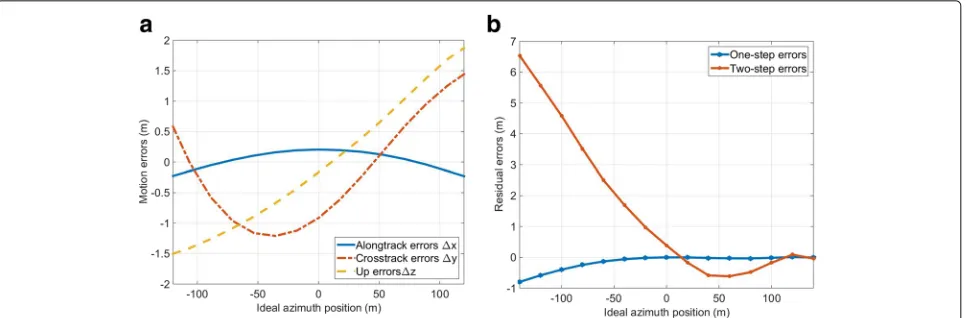
Fig. 3Real measured motion error and corresponding residual RCMC envelope error.aReal-measured motion error.bCorresponding residual
wherexdenotes the azimuth position of the target. In this section, we mainly focus on providing the comparison of RCMC envelope error between the two-step and one-step MOCO, which is expressed asϑ1in (19). Order
u(X)= − H
Substituting (29) into (19), the RCMC envelope error for the two-step MOCO is given by:
T1≈
Table 1Simulation parameters
Carrier frequency 35 GHz
Pulse repetition frequency 2000 Hz
Velocity 70 m/s
Pulse width 2μs
Center closest slant range 4000 m
Squint angle 5◦
Grazing angle 45◦
Range resolution 0.15 m
Azimuth resolution 0.15 m
Point A coordinate (0, 400)
Point B coordinate (0, 0)
Point C coordinate (0,−400)
Similarly, substituting (30) into (19), the RCMC enve-lope error for the one-step MOCO is given by:
T2≈ (
where the azimuth-dependent motion errorδRahas little impact on the RCMC envelope, so it is not considered in this paper. The ratio betweenT1andT2is expressed as:
where the numerator of (32) represents the range differ-ence between target and scene center and the denomina-tor represents the length of range walk. It’s clear that the RCMC envelope error is in proportion to the range dif-ference for two-step MOCO, so the imaging performance would be seriously destroyed at the points far from scene center line. However, in some cases, the effect of resid-ual range-dependent motion error could be neglected if the maximum of RCMC envelope is within 1/4 rang bin, which is shown as:
maxRE+
where max|·|denotes the maximum of the absolute value. For the two-step MOCO, the inequality becomes:
maxrs−r
And for the one-step MOCO, the inequality becomes:
Wanget al. EURASIP Journal on Advances in Signal Processing (2016) 2016:115 Page 7 of 11
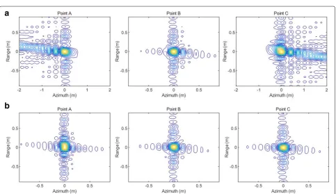
Fig. 4Comparison of the two-step MOCO and one-step MOCO in RCMC results of points A, B and C.aTwo-step MOCO results.bOne-step MOCO results
Fig. 6Comparison of the two-step MOCO and one-step MOCO in azimuth pulse response curves of points A, B, and C
It could be found that, for SAR imaging with wide swath, the requirement of inequation (34) is hard to satisfy at points far from the scene center line, while inequation (35) is easier to meet. A simulation result of the RCM error comparison with real-measured trajectory devia-tions between the two-step and one-step MOCO is shown in Fig. 3. The trajectory deviations are extracted from a real position and orientation system shown in Fig. 3a. The residual RCMC envelope error is calculated with a squint angle of 5◦ and a pitch angle of 45◦, the center closest slant range is 4000 m, and the range difference between target and scene center is 100 m. The corresponding resid-ual RCMC envelope errors are shown in Fig. 3b. It is clear that the envelope error of the two-step MOCO is up to several meters, while the one-step MOCO significantly overcomes this problem.
3.2 Computational burden analysis
In this subsection, the computational burden of the one-step and two-step MOCO-based SAR imaging algo-rithms is respectively measured by operating number of fast Fourier transform (FFT), inverse fast Fourier trans-form (IFFT), and complex multiplication for compari-son. As shown in Fig. 2, suppose the azimuth and range point numbers are denoted by Na and Nr. It needs to be noticed that we analyze the operand by merg-ing adjoinmerg-ing phase terms and without regard of the calculation of PTA operation. For the one-step MOCO-based imaging algorithm, there are 4Na timesNr-point FFT/IFFT operators, 2NrtimesNa-point FFT/IFFT oper-ators, and 5 timesNr×Na-point complex multiplications to obtain a focused imaging. Comparing with the conven-tional two-step based imaging algorithm, there are 2Na timesNr-point FFT/IFFT operators, 2NrtimesNa-point FFT/IFFT operators, and 5 times Nr × Na-point com-plex multiplications. It could be found that the one-step MOCO-based imaging algorithm adds 2Nr more times Na-point FFT/IFFT operators, which slightly increases
the computational burden and exchanges for a better focused imagery.
4 Simulated and real data experiments
4.1 Experiments with simulated data
In this subsection, a group of point target simulation experiments are set to demonstrate the effectiveness of the one-step MOCO-based imaging algorithm compared with the two-step MOCO-based imaging algorithm. Sim-ulation parameters and three-point target coordinates are shown in Table 1. It needs to be emphasized that points A and C are far from the scene center line, while point B lies on the scene center line. In this simulation experiment, the performance of the one-step MOCO imaging algorithm is validated by simulated data mixed with motion errors which are extracted from airborne INS, which are shown in Fig. 3a.
At first, we present the comparison of RCMC error with respect to the residual range-dependent motion error between the two-step MOCO and one-step MOCO. In order to illustrate the RCMC error explicitly, the range profile of three points are shown in two-dimensional time domain. It could be easily found in Fig. 4a that the residual RCMs of points A and C are obvious, except for point B because it is lying on the scene cen-ter line without range-dependent motion error before RCMC. These RCMC errors are deemed to coincide well
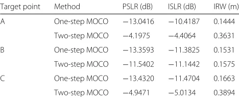
Table 2Focusing performance comparison between two focusing algorithms
Target point Method PSLR (dB) ISLR (dB) IRW (m)
A One-step MOCO −13.0416 −10.4187 0.1444
Two-step MOCO −4.1975 −4.4064 0.3631
B One-step MOCO −13.3593 −11.3825 0.1531
Two-step MOCO −11.5402 −11.1442 0.1575
C One-step MOCO −13.4320 −11.4704 0.1663
Wanget al. EURASIP Journal on Advances in Signal Processing (2016) 2016:115 Page 9 of 11
Table 3Experiment parameters
Carrier frequency 35 GHz
Pulse repetition frequency 5000 Hz
Velocity 70 m/s
Pulse width 20μs
Center closest slant range 4000 m
Squint angle 5◦
Grazing angle 45◦
Range resolution 0.15 m
Azimuth resolution 0.15 m
with the expression of ϑ1 in (19). It is also shown in Fig. 4a that the residual RCMC errors of points A and C processed by two-step MOCO are spanning across several range cells, so the focusing performance would be seriously damaged. The RCM corrected range pro-files of points A, B, and C processed by the one-step MOCO are shown in Fig. 4b for comparison, while all the RCMC errors of points A, B, and C are well removed.
Then, azimuth compression performance of the one-step MOCO-based imaging algorithm is investigated. The two-dimensional images of points A, B, and C processed by the conventional two-step MOCO-based imaging algo-rithm and one-step MOCO-based imaging algoalgo-rithm are shown in Fig. 5. Because of the existence of residual RCMC errors, the imaging algorithm based on the con-ventional two-step MOCO fails to focus in azimuth for points A and C, as shown in Fig. 5a. While the well-focused imaging results of points A, B, and C processed by the one-step MOCO-based imaging algorithm are shown in Fig. 5b. Figure 6 shows the comparison of azimuth point
spreading response of points A, B, and C. In order to eval-uate the focused improvement of the proposed algorithm comparing with the conventional one, three quantita-tive metrics are introduced to measure the point impulse responses of points A, B, and C, which are shown in Table 2. The quantitative metrics are peak side-lobe ratio, (PSLR), integrated side-lobe ratio (ISLR), and impulse response width (IRW). It is obvious that the focusing degradation of the conventional two-step MOCO-based imaging algorithm is overcame by the one-step MOCO-based imaging algorithm, especially for points A and C, which are far from the scene center line.
4.2 Experiments with real-measured data
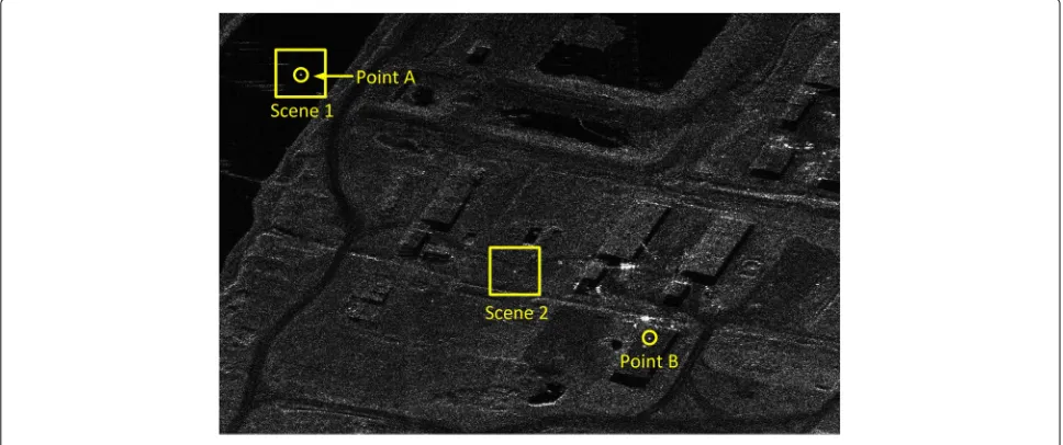
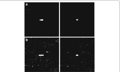
In this subsection, a set of comparison experiment is pro-vided based on the processing of measured data recorded by an experimental airborne MMW SAR system. The instantaneous position and motion parameters of plat-form are measured by a high-accuracy INS equipped on the platform. Detailed radar parameters are shown in Table 3. An imaging result processed by the one-step MOCO-based imaging algorithm is shown in Fig. 7. In order to compare the imaging performance between the conventional two-step MOCO-based imaging algo-rithm and one-step MOCO-based imaging algoalgo-rithm more vividly, two typical areas named scene 1 and scene 2 with obvious point-like targets are highlighted by the yellow rectangles in the scene. The picked two scenes are respectively magnified in Fig. 8a, b for imaging perfor-mance comparison, where the two-step MOCO imaging results are lied on the left, while the one-step MOCO imaging results are lied on the right. It is shown that defocusing of targets in the images is distinct for the two-step MOCO-based imaging algorithm, and the one-two-step
Fig. 8Comparison of the two-step MOCO-based imaging algorithm and one-step MOCO-based imaging algorithm in local amplification results of scene 1 and scene 2.aComparison of scene 1 (the two-step MOCO-based imaging result is on theleft, the one-step MOCO-based imaging result is on theright).bComparison of scene 2 (two-step MOCO-based imaging result is on theleft, the one-step MOCO-based imaging result is on theright)
MOCO significantly removes the RCMC error, so the tar-gets are well focused. Moreover, in order to check the azimuth point spreading response improvement of the one-step MOCO-based imaging algorithm, two isolated point-like targets named point A and point B are extracted from Fig. 7 by yellow circle for azimuth point spreading response function comparison. The comparison results of point A and point B are shown in Fig. 9a, b, respectively. A better azimuth pulse response function could be obtained
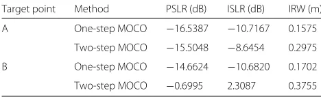
by the one-step MOCO-based imaging algorithm, com-pared with the two-step. The quantitative analysis results of the azimuth point spreading response functions of Fig. 9 are listed in Table 4. It could be found in the exper-iments above that, focusing performance is sensitive to the residual RCMC error especially for high-resolution MMW SAR imaging, so conventional two-step MOCO-based imaging algorithm is not suitable for this case. The one-step MOCO removes the range-dependent motion
Wanget al. EURASIP Journal on Advances in Signal Processing (2016) 2016:115 Page 11 of 11
Table 4Focusing performance comparison of points A and B between two focusing algorithms
Target point Method PSLR (dB) ISLR (dB) IRW (m)
A One-step MOCO −16.5387 −10.7167 0.1575
Two-step MOCO −15.5048 −8.6454 0.2975
B One-step MOCO −14.6624 −10.6820 0.1702
Two-step MOCO −0.6995 2.3087 0.3755
error before RCMC, so that the range profile after RCMC is accurate.
In order to verify the calculation analysis in Section 2, we record the calculation time for both two-step and one-step MOCO-based SAR imaging algorithms. The computer platform is installed with Windows10 64-bit operating system, Core [email protected] CPU, 16-GB memory and Matlab with version of R2015a. A block of 16, 384×8192 (range×azimuth) points SAR data is used for test, the whole data is divided into four sub-blocks in azimuth, and the calculation time of the two-step and one-step MOCO-based imaging algorithms are 855.13s and 909.49s, respectively. With the nearly equal computa-tion complexity compared with the two-step MOCO, the one-step MOCO is applicative for practical MMW SAR imaging application.
5 Conclusions
The conventional two-step MOCO algorithm remains the range-dependent motion error before RCMC, which decreases the accuracy of RCMC in two-dimensional wavenumber domain, inducing serious envelope and phase error to the range profile. In this paper, analytical expressions of these errors are deduced in detail. The one-step MOCO-based imaging algorithm is also investigated to compare with the conventional two-step MOCO-based imaging algorithm, which removes the range-dependent motion error before RCMC, so the RCMC error is sig-nificantly suppressed. Simulations and measured MMW data experiments illustrate the outperforms of the one-step MOCO-based SAR imaging algorithm, which verify the analysis in this paper.
Acknowledgements
The authors thank the anonymous reviewers for their valuable comments to improve the paper quality. This work was supported by the National Natural Science Foundation of China under grant numbers 61301280 and 61301293 and the High-Resolution Earth Observation System Major Special Project Youth Innovation Foundation of China under grant number GFZX04060103.
Competing interests
The authors declare that they have no competing interests.
Author details
1National Lab of Radar Signal Processing and the Collaborative Innovation Center of Information Sensing and Understanding, Xidian University, Xi’an 710071, People’s Republic of China.2Beijing Institute of Radio Measurement,
The Second Academy of China Aerospace Science and Industry Corporation (CASIC), Beijing 100854, People’s Republic of China.
Received: 13 May 2016 Accepted: 28 October 2016
References
1. MD Xing, XW Jiang, RB Wu, et al, Motion compensation for UAV SAR based on raw radar data. IEEE Trans. Geosci. Remote Sensing.47(8), 2870–2883 (2009)
2. AE Azouz, ZF Li, Improved phase gradient autofocus algorithm based on segments of variable lengths and minimum-entropy phase correction. IET Radar Sonar Navigation.9(4), 467–479 (2015)
3. L Zhang, MD Xing, ZQ Qiao, Wavenumber-domain autofocusing for highly squinted UAV SAR imagery. IEEE Sensors J.12(5), 1574–1588 (2012) 4. A Moreira, YH Huang, Airborne SAR processing of highly squinted data
using a chirp scaling approach with integrated motion compensation. IEEE Trans. Geosci. Remote Sensing.32(5), 1029–1040 (1994)
5. WG Carrara, RM Majewshi, RS Goodman,Spotlight Synthetic Aperture Radar Signal Processing Algorithm. (Artech House, Boston, 1995), pp. 15–27 6. CV Jakowatz, DE Wahl, PH Eichel, et al,Spotlight Mode Synthetic Aperture
Radar: a Signal Processing Approach. (Kluwer Academic Publisher, Boston, 1996), pp. 252–267
7. I Cumming, F Wong,Digital Processing of Synthetic Aperture Radar Data: Algorithms and Implementation. (Norwood, Artech House, 2005) 8. WQ Wang, QC Peng, JY Cai, Waveform-diversity-based millimeter-wave
UAV SAR remote sensing. IEEE Trans. Geosci. Remote Sensing.47(3), 691–700 (2009)
9. RK Raney, H Runge, IG Cumming, et al, Precision of SAR processing using chirp scaling. IEEE Trans. Geosci. Remote Sensing.32(4), 786–799 (1994) 10. GW Davidson, ID Cumming, MR Ito, A chirp scaling approach for
processing squint model SAR data. IEEE Trans. Aerospace Electronic Syst. 32(1), 121–133 (1996)
11. MD Yang, DY Zhu, W Song, Comparison of two-step and one-step motion compensation algorithms for airborne synthetic aperture radar. Electron. Lett.51(14), 1108–1110 (2015)
12. R Bamler, A comparison of range-doppler and wavenumber domain SAR focusing algorithm. IEEE Trans. Geosci. Remote Sensing.30(4), 706–713 (1992)
13. A Reigber, E Alivizatos, A Potsis, et al, Extended wavenumber-domain synthetic aperture radar focusing with integrated motion compensation. IET Radar Sonar Navigation.153(3), 301–310 (2006)
14. KAC Macedo, R Scheiber, Precise topography- and aperture-dependent motion compensation for airborne SAR. IEEE Geosci. Remote Sensing Lett.2(2), 172–176 (2005)
15. P Prats, KAC Macedo, A Reigber, et al, Comparison of topography- and aperture-dependent motion compensation algorithms for airborne SAR. IEEE Geosci. Remote Sensing Lett.4(3), 349–353 (2007)
16. P Prats, A Reigber, JJ Mallorqui, Topography-dependent motion compensation for repeat-pass interferometric SAR systems. IEEE Geosci. Remote Sensing Lett.2(2), 206–210 (2005)
17. S Perna, V Zamparelli, A Pauciullo, et al, Azimuth-to-frequency mapping in airborne SAR data corrupted by uncompensated motion errors. IEEE Geosci. Remote Sensing Lett.10(6), 1493–1497 (2013)
18. A Potsis, A Reigber, J Mittermayer, et al, Sub-aperture algorithm for motion compensation improvement in wide-beam SAR data processing. Electron. Lett.37(23), 1405–1407 (2001)