R E S E A R C H
Open Access
Study of double rotor speed-regulating
wind power generation system
Yanan Li, Peng Yang
*and Huajun Wang
Abstract
Large-scale wind turbines have become the trend of the wind power industry. However, the main factors restricting the large scale wind turbines are frequent replacement of carbon brush and slip ring and the harmonic of the stator current in double-fed induction generator, plus converters’large volume, high cost, and high failure rate in full power converter of wind turbine. Therefore, new double rotor speed-regulating wind power generation system comprising a double rotor speed-regulating device connected to the gearbox and the synchronous generator is proposed for the sake of lower cost, higher reliability, and stronger adaptability of the power grid. The structure of the system and the connection of each component are described; meanwhile, the working principle of the system under different operating conditions is analyzed. Furthermore, the mathematical model of the system is established, besides the control strategy being proposed. The simulation results verify the correctness of the mathematical model and the control strategy.
Keywords:Wind power, Double rotor generator, Speed-regulating device, Mathematical model, Large-scale wind turbines, Grid adaptability
1 Introduction
Wind power has become an important object of R&D around the world as an effective measure to solve the current energy crisis and environmental contamination. Nevertheless, double-fed induction generator (DFIG) and permanent magnetic synchronous generator (PMSG) have the disadvantages of poor grid-connected capacity when the wind turbines become large scale.
Internet of things relies on the development of tech-nology referred to as ABC: A is artificial intelligence, B is big data, and C refers to cloud computing. For the wind power market, it is necessary to rely on ABC tech-nology, combined with the characteristics of the wind power industry, in order to be in the dominant position in the market competition. First of all, in the artificial intelligence, the amount of data and the complexity of the algorithm will be greatly improved. The simulation data will also be included in the sequence of calculation and training, which makes the speed of intelligence fas-ter, and the intelligence of the equipment on this basis will be more and more high. Meanwhile, big data will no
longer be a single list of concepts, but will become the core of the infrastructure, and the automatic data gener-ated by the device (including human self ) will be far more than the data generated by human social behavior, cloud to end, end to end, cloud to cloud, and big data will be ubiquitous in the way of network. Furthermore, with the increase of mass data and the increasing de-mand of machine learning for real time, and the high coupling of business logic, the way of public cloud will no longer fit the Internet of things. The mode of mini data center will replace the public cloud. The data deci-sion processing will be closer to the data source, and the edge computing will become the mainstream. Therefore, the real-time nature of the Internet of things will make the operation of the wind power more intelligent and will have a far-reaching impact on the change of the wind power service industry.
As far as the DFIG is concerned, the use of the high variable ratio gearbox increases the failure rate of the wind turbine generator system to reduce the reliability [1]. Meanwhile, the carbon brushes and slip rings are available in the generator rotor [2]. In general, the carbon brush is replaced every 6 months and the slip ring is re-placed every 2 years, resulting in the high maintenance * Correspondence:[email protected]
School of Artificial Intelligence, Hebei University of Technology, Tianjin, China
frequency and high cost [3]. Moreover, the generator stator is directly connected with the power grid, plus the rotor current is in constant change, so the stator output current is more harmonic and difficult to control [4]. The inflow of the harmonic current to the power grid will cause the following negative effects [5]. Firstly, the har-monics increase the loss of transmission lines and trans-formers, accelerate the insulation aging of the equipment, shorten the service life, and even lead to equipment scrap-ping [6]. Secondly, the harmonic causes the protection de-vice malfunction, which leads to the inaccuracy of the electrical measurement instrument [7]. Thirdly, the har-monic leads to the local parallel or series resonance of the power grid to further amplify the harmonics, and then re-sults in the instability of the power grid [8].
Compared with DFIG, PMSG has no carbon brush and slip ring, so the maintenance performance is better than DFIG [9]. Specifically, the harmonic frequency of the stator output current is stable and easy to control [10]. Besides, the generator and the power grid are iso-lated by the full power converter, so there is no current impact and the power grid adaptability is stronger [11]. However, due to the use of the full power converter, the converter has large capacity, large volume, and high loss, which brings about high cost of manufacturing and op-eration [12]. In addition, the converter has been the higher failure rate component of the PMSG, which re-duces the reliability and increases the maintenance cost of the PMSG [13].
Therefore, the new concept of speed-regulating wind turbine is presented. That is to say, variable wind speed is regulated to a constant speed by the speed-regulating device between the wind turbine and the generator, so synchronous is driven to output constant frequency elec-tric power.
A new type of variable speed constant frequency wind turbine which combines the hydraulic coupling speed-regulating device called Windrive with the conventional synchronous generator has been proposed by Dewind [14]. The working principle is shown in Fig.1.
Windrive is a speed controller composed of planetary gear and torque converter, which is responsible for necting the high-speed shaft of the gearbox and the con-stant speed synchronous generator shaft to ensure the
variable speed constant frequency operation of the wind turbine and capture the maximum wind energy [15].
But the Windrive also has existing weaknesses. Firstly, the hydraulic torque converter absorbs the energy from the power grid to regulate the speed in lower wind speed period of time, which reduces the generating efficiency [16]. Secondly, the hydraulic torque converter is gener-ally required for the operating environment, so its ap-plicability in the harsh natural environment of the wind farm remains to be verified [17]. Thirdly, variable speed constant frequency operating range of wind turbine with hydraulic torque converter is restricted [18]. Fourthly, the manufacturing cost of the torque converter is high, which leads to the failure of mass production.
Therefore, a new type of variable speed constant fre-quency wind turbine based on the electromagnetic coupler has been proposed by Tsinghua University. The hydraulic coupling device has been replaced by frequency control electromagnetic coupler, so that the high-speed output shaft of the gear box is connected with the gener-ator shaft in a noncontact way. The structure is shown in Fig.2.
The advantages of the wind turbine with electromag-netic coupler are as follows: firstly, the wind turbine can carry out stepless speed regulation due to non-contact flexible drive device like electromagnetic coupler [19]. Secondly, the speed-regulating range of the wind turbine is wider, and the utilization rate of wind energy is higher in lower wind speed period of time [20]. Thirdly, the re-sponse speed of the wind turbine is fast and the adjust-ment is stable due to the transfer torque of the electromagnetic coupler controlled by converter [21].
However, the volume and weight of the wind turbine are equivalent to about two times that of the same cap-acity wind turbine by using electromagnetic coupler re-placed hydraulic torque converter, which increases the difficulty of transportation and lifting. Furthermore, only can the electromagnetic coupler achieve speed regula-tion through adjusting the torque and speed of the wind turbine, so the generating efficiency of wind turbine needs to be improved. In addition, the high cost of elec-tromagnetic coupler is also a crucial factor which re-stricts mass production of the electromagnetic coupling speed-regulating wind turbine.
Based on the analysis of the characteristics of two kinds of speed-regulating wind turbines mentioned above, a new type of driving chain of speed-regulating wind turbine is proposed in this paper, which achieves speed regulating and generating simultaneously in a certain period of time to reduce the capacity of generator and converter. More-over, the range of variable speed constant frequency of the wind turbine is wider, and the generating efficiency and reliability are improved on the basis of stronger grid adaptability.
2 Structure of the double rotor speed-regulating wind power generation system
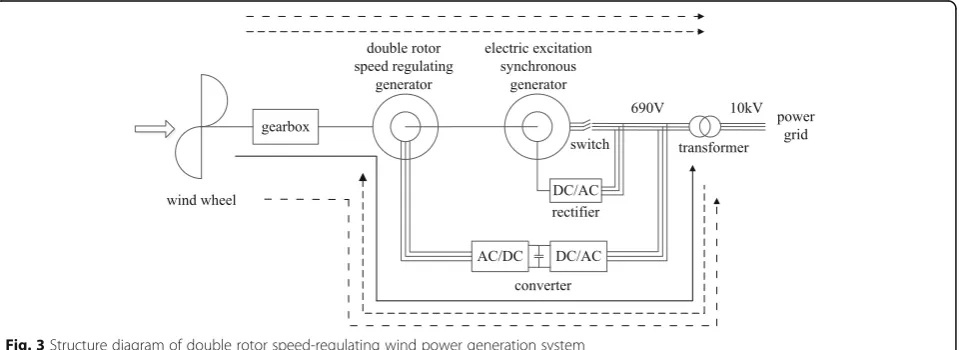
The structure of the double rotor speed-regulating wind power generation system is shown in Fig. 3. It is mainly composed of the wind wheel, gearbox, double rotor speed-regulating generator, electric excitation synchronous generator, converter, rectifier, transformer, and switch. The double rotor speed-regulating gener-ator comprises a permanent magnet outer rotor and a wound inner rotor. The permanent magnet outer rotor is mechanically connected to the gear box, besides the wound inner rotor is coaxially connected with the rotor
of electric excitation synchronous generator as well as is electrically connected with the converter.
3 Working principle and operation state of double rotor speed-regulating wind power generation system
3.1 Working principle
The rotational speed of the double rotor speed-regulat-ing generator can be obtained as shown in formula (1) since the rotating magnetic field formed by inner and outer rotor of the speed-regulating generator must re-main relatively static to achieve stable mechanical and electrical energy conversion according to the electromech-anical principle.
nout¼ninþnf ð1Þ
wherenoutis the rotational speed of the outer rotor under
external forces, nin is the mechanical speed of the inner
rotor, andnfis the rotational speed of the rotating magnetic
field generated by the current from the wound inner rotor.
The power of the double rotor speed-regulating gener-ator can be obtained as shown in formula (2) according to the energy conservation law.
Fig. 2Electromagnetic coupling speed-regulating wind turbine structure diagram
PmþPf¼PL ð2Þ
where Pm is the input mechanical power of the
speed-regulating generator, Pf is the electrical power of the
speed-regulating generator, and PL is the output
mech-anical power of the speed-regulating generator.
The torque transmission of the speed-regulating gen-erator as shown in formula (3) can be deduced by the formula (2).
TmωoutþTeωf ¼TLωin ð3Þ
where ωout andωin are the mechanical angular velocity
of the outer and inner rotor of the speed-regulating gen-erator respectively,ωfis the angular velocity of the
rotat-ing magnetic field formed by the current of the wound inner rotor, Te is the electromagnetic torque of the
speed-regulating generator, andTmand TL are the input
and output mechanical torque of the speed-regulating generator respectively.
The electromagnetic torque expression of the speed-regulating generator as shown in formula (4) can be de-rived from the formula (3).
Te¼TLωin−Tmωout
ωout−ωin ð
4Þ
It is known by the formula (4) that the electromag-netic torque of the speed-regulating generator declines logarithmically with the increase of the inner and outer rotor speed.
3.2 Operating state
Five operating states of the double rotor speed-regulating wind power generation system are as follows:
State I Speed-regulating generator generates electricity State II Speed-regulating generator speed regulating State III Speed-regulating generator speed regulates and generates electricity simultaneously
State IV Constant speed-operating state State V Constant power-operating state (rated operating state)
3.2.1 State I
The inner rotor of the speed-regulating generator co-axially connected with the rotor of the synchronous generator is equivalent to a stator because the syn-chronous generator is not connected with the power grid. That means the system is equivalent to the full-power converter wind turbine generator with per-manent magnet outer rotor and wound inner stator.
The outer rotor speed nout of the speed-regulating
generator increases from zero with the rise of wind speed v since the wind speed reaches cut in value vin,
and the output power of the speed-regulating generator
to the power grid is Pf. The synchronous generator is
connected with the power grid as soon asPfreaches the
rated powerPfNof the speed-regulating generator. From
this moment on, the system will operate in the state II, and the wind speed of this moment isv1.
The power flow of the system in the state I is as shown in the solid line in Fig. 3. The wind energy absorbed by the wind wheel is converted to electricity by the speed-regulating generator and then transferred to the power grid.
3.2.2 State II
The outer rotor speed nout continually increases with
the rise of the wind speed since the wind speed exceeds v1. The inner rotor of the speed-regulating generator
coaxially connected with the rotor of the synchronous generator starts to rotate as the synchronous generator is connected with the power grid, that is, the inner rotor speed ninincreases from zero. The frequency fof
the inner rotor winding current is regulated and con-trolled in order that the inner rotor speed nin rapidly
reaches and stabilizes at the synchronous speedn0, that
is nout<nin=n0. The speed-regulating generator is in
the state of speed regulating as the converter absorbs ac-tive power from the power grid to the speed-regulating generator, that is to say, the output power of the speed-regulating generator is positive, Pf> 0, besides the
output powerPfof the speed-regulating generator first
in-creases and then dein-creases with the speed difference be-tween the inner and outer rotor. The converter provides DC excitation for the speed-regulating generator as soon as the outer rotor speednoutincreases to the
syn-chronous speedn0with the rise of the wind speed, that
is, nout=nin=n0,Pf= 0. From this moment on, the
sys-tem will operate in the state III, plus the wind speed of this moment isv2.
The power flow of the system in the state II is as shown in the dotted line in Fig. 3. The wind energy absorbed by the wind wheel and speed regulated through the speed-regulating generator is transferred to the syn-chronous generator and then transported to the power grid. Simultaneously, the converter absorbs part of the power from the grid to provide to the speed-regulating generator.
3.2.3 State III
The outer rotor speed nout continues to increase with
the wind speed rising since the wind speed exceeds v2.
That is nout>nin=n0. The speed-regulating generator is
in the state of speed regulating and generating electricity as it outputs active power to the power grid through the converter, that is to say, the output power of the speed-regulating generator is negative,Pf< 0, besides the
speed-regulating generator increases with the speed dif-ference between the inner and outer rotor. The system will operate in the state IV as soon as the outer rotor speed increases to its rated speed with the wind speed rising, that is, nout=noutN, and the wind speed of this
moment isvωN.
3.2.4 State IV
The outer rotor speednout has already reached the rated
value noutN since the wind speed exceeds vωN, whereas
the output power Pf of the speed-regulating generator
has not reached the rated value PfN; thus, the output
power Pf continues to increase as the wind speed rises
while the outer rotor speed keeps stable. The system operates in the constant power operation state as soon as the output power of the speed-regulating generator is increased to the rated value PfN. From this moment on,
the system will operate in the state V, and the wind speed of this moment isvN.
3.2.5 State V
The system operates in the rated operating state by adjusting the pitch angle to limit the wind energy captured by the wind wheel since the wind speed ex-ceeds vN. That is to say, the outer rotor speed of the
speed-regulating generator is the rated speed noutN,
besides the output power of the speed-regulating generator is the rated powerPfN. In addition, the
out-put power of the synchronous generator is the rated powerPSN.
The power flow of the system in the states III to V is as shown in the dash-dotted line in Fig.3. A part of the wind energy absorbed by the wind wheel and speed regulated through the speed-regulating generator is transferred to the synchronous generator and then transported to the power grid. Meanwhile, the other is converted to electricity through the converter and then transferred to the power grid. In this way, a double feeder of electricity is realized.
The synchronous generator provides the rated power PSN to the power grid as the rotor speed nrreaches the
rated speedn0in the states II to V.
The trend of the speed and power of the double rotor speed-regulating wind power generation system under different wind speeds is as shown in Fig.4.
4 Mathematical model and control strategy of the double rotor speed-regulating generator
4.1 Mathematical model
Referring to the mathematical model of the PMSG, taking the inner rotor of the double rotor speed-regulating gener-ator as the reference coordinate, the mathematical model of the double rotor speed regulating generation, the dq co-ordinate system is established, such as the voltage and
current equation is shown in (5) and (6), the torque equa-tion is shown in (7), and the moequa-tion equaequa-tion is shown in (8) and (9). The dq coordinate system is rotated by the ro-tational speed difference between the inner and outer rotor, that isωout−ωin.
ud¼RidþLddid
dt −pðωout−ωinÞLqiq ð5Þ
uq¼RiqþLqdiq
dt þpðωout−ωinÞLdid þpðωout−ωinÞψf
ð6Þ
Te¼ 3
2piq Ld−Lq
idþψf
ð7Þ
Joutdωout
dt ¼Tm−Te ð8Þ
Jindωin
dt ¼Te−TL ð9Þ
terminal voltage (phase voltage) of the inner rotor, re-spectively. id and iq are the dq axis components of the
inner rotor current, respectively.Ris the inner rotor re-sistance. Ld and Lq are the dq axis components of the
inner rotor inductance, respectively.ωoutand ωinare the
mechanical angular velocity of the outer and inner rotor, respectively. p is the pole pairs of the double rotor speed-regulating generator. ψf is the flux of the outer
rotor permanent magnet. Te is the electromagnetic
torque of the double rotor speed-regulating generator.
Tm and TL are the input and output torque of the
double rotor speed-regulating generator, respectively.Jin
andJoutare the moment of inertia of the inner and outer
rotor, respectively.
4.2 The control strategy of the outer rotor
According to the different wind speed, the control strategy of the outer rotor of the double rotor speed-regulating generator is as follows. The maximum power point track-ing (MPPT) control strategy is adopted when the wind speed is lower than the rated wind speed. (State I to state IV) The outer rotor can get the optimal torque by control-ling the active component of the inner rotor current to ensure that the double rotor speed-regulating wind power generation system operates in the state of maximum wind energy capture. The pitch control strategy is adopted when the wind speed exceeds the rated wind speed. (State V) The output power of the system can be limited in the vicinity of the rated power by adjusting the pitch angle since the mechanical strength and generator capacity are limited.
4.2.1 Maximum power point tracking (MPPT) control strategy
The vector control strategy of id= 0 is adopted in this
paper. When id= 0, the torque equation of the double
rotor speed-regulating generator is shown in formula (10) according to the formula (7).
Te¼ 3
2piqψf ð10Þ
The formula (10) shows that the torque of the double rotor speed-regulating generator is only related to the q axis current. Therefore, controlling theqaxis current can control the torque of the double rotor speed-regulating generator and then control the outer rotor to track the maximum power point.
The outer rotor maximum power point tracking con-trol structure diagram is shown in Fig. 5. The double closed loop control strategy with speed outer loop and current inner loop is adopted (ωf=ωout−ωin).
The speed deviation is obtained by comparing the reference speed signal ωf with the feedback speed sig-nalωf, and then input the speed deviation to the speed
controller to get the reference torque current signal iq.
The current deviation of the q axis and thed axis are respectively obtained by comparing the reference current signal iq and id¼0 with the feedback current
signal iq and id, respectively, and then input the
current deviation to respective current controller to get the reference voltage signal uq and ud. After that
uαanduβare obtained from coordinate transformation
to get the driving signal of the dual PWM converter by SVPWM modulating.
4.2.2 Pitch control strategy
The power captured by the wind turbine is main-tained at a constant value by the variable pitch con-trol mechanism in order to avoid the damage to the wind turbine in the process of the system transmit-ting the rated power to the grid when the wind speed exceeds the rated wind speed but is lower than the cut-out wind speed. The blade will be gradually ro-tated to the tailwind direction with the wind speed increasing. The pitch control structure diagram is shown in Fig. 6.
In Fig. 6, ωoutN is the outer rotor rated angular
vel-ocity of the double rotor speed-regulating generator.
ωout is the outer rotor actual angular velocity of the
double rotor speed-regulating generator. PN is the
rated output power of the system. P is the actual out-put power of the system. max is the larger value in PN and P. The regulation of β is divided into two
ways. One is to control the difference between the outer rotor rated speed and its actual speed of the double rotor speed-regulating generator with PI con-troller. The other is to control the difference between the larger value in actual power and rated power and the rated power of the double rotor speed-regulating generator with proportional controller. The outer rotor speed and the output power of the double rotor speed-regulating wind power generation system are maintained at the rated value by increasing the pitch angle to reduce the wind turbine airfoils Cp when the
outer rotor actual speed exceeds the rated speed or the system actual output power exceeds the rated output power.
5 Experimental
The simulation is carried out in MATLAB/Simulink based on the mathematical model of the double rotor speed-regulating generator and the outer rotor control
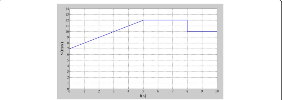
strategy. The simulation parameters are as follows: the rated wind speed is 12 m/s, the impeller radius is 40 m, the pitch angle is zero, the rated speed of the wind tur-bine is 23 r/min, the rated power of the double rotor speed regulating generator is 500 kW, and the rated voltage is 690 V.
The double rotor speed-regulating wind power gener-ation system will operate in the state II when the wind speed reaches 7 m/s by calculating, so the trend of wind speed is set as shown in Fig.7.
The trend of outer rotor speed of the double rotor speed-regulating generator with the wind speed change is shown in Fig.8.
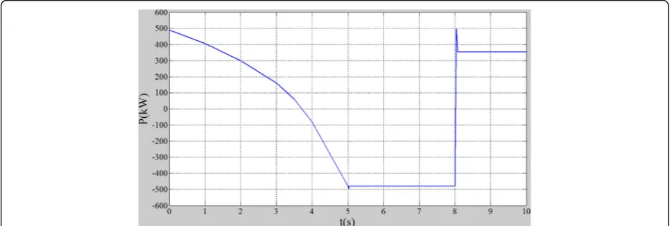
The power of the double rotor speed-regulating gener-ator is shown in Fig.9.
6 Results and discussion
From Fig. 8, we can see that the outer rotor speed can track the change of the wind speed quickly and accurately to achieve the maximum wind energy tracking under the maximum power point tracking control. Therefore, the correctness of the control strategy is verified.
In combination with Figs. 8 and 9, it is known that before 3.75 s, ωout<ωin (157 rad/s), Pf> 0, so the
double rotor speed-regulating generator is in power-driven state and absorbs active power from the power grid. During the period of 3.75~5 s, ωout>ωin
(157 rad/s),Pf< 0, so the double rotor speed-regulating
generator is in generation state and sends out active power to the power grid. At the time of 8 s, the wind speed is abrupt, and the double rotor speed-regulating generator is switched from the generation (Pf< 0) to
power-driven (Pf> 0) state.
This paper only discusses the control strategy of the outer rotor of the double rotor speed-regulating Fig. 6Pitch control structure
generator under the rated wind speed, and the control strategy of the system for the whole wind speed range is still to be studied.
7 Conclusions
The double rotor speed-regulating wind power gener-ation system has the ability of speed regulgener-ation and power generation at the same time in a certain period of time and reduces the capacity of the generator and converter as a new type of driving chain of speed-regulating wind turbine. Moreover, the system can realize the capability of active power overload and re-active power support of the power grid since the syn-chronous generator is directly connected with the power grid at the end of the driving chain. Further-more, the variable speed constant frequency operation of the system in the whole wind speed range is
guaranteed by multimode operating state under differ-ent wind speeds so as to capture the maximum wind power. In addition, the damage of the synchronous generator caused by wind speed fluctuation is reduced as the double rotor speed-regulating generator con-necting the gearbox and the synchronous generator, so the reliability of the system is improved. Therefore, the double rotor speed-regulating wind power gener-ation system has a wide applicgener-ation prospect to allevi-ate the energy crisis and respond to the worsening natural environment.
The research only discusses the PI control strategy of the outer rotor of the double rotor speed-regulating gen-erator under the rated wind speed, and the control strat-egy of the system for the whole wind speed range is still to be studied. In addition, the transient process of differ-ent operating state needs to be studied. Besides, Fig. 8Outer rotor speed of the double rotor speed-regulating generator. In Fig.8,X-axis is time (s) andY-axis is outer rotor speed (rad/s)
advanced control algorithms can also be applied to the double rotor speed-regulating wind power generation system to achieve desirable effect.
Abbreviations
DFIG:Double-fed induction generator; PMS: Permanent magnetic synchronous generator; R&D: Research and development
Authors’contributions
YL is the main writer of this paper. She proposed the main idea, completed the simulation, and analyzed the result. PY and HW gave some important suggestions for this paper. All authors read and approved the final manuscript.
Competing interests
The authors declare that they have no competing interests.
Publisher’s Note
Springer Nature remains neutral with regard to jurisdictional claims in published maps and institutional affiliations.
Received: 20 March 2018 Accepted: 30 May 2018
References
1. Control methodology for compensation of grid voltage unbalance using a series-converter scheme for the DFIG. Suppioni, Vinicius P. (Centro de Engenharia, Modelagem e Ci&ecire;ncias Sociais Aplicadas, Universidade Federal Do ABC, Santo André, Brazil); Grilo, Ahda P.; Teixeira, Julio C. Source: Electr. Power Syst. Res.133, 198–208, 2016
2. L Li, H Nian, L Ding, Direct power control of DFIG system without phase-locked loop under unbalanced and harmonically distorted voltage. IEEE Trans. Energy Convers.33, 395–405 (2018)
3. Fuzzy logic control of grid connected DFIG system using back-to-back converters. Dida, Abdelhak (Department of Electrical Engineering, Biskra University, Biskra; 07000, Algeria); Ben Attous, Djilani Source: Int. J. Syst. Assur. Eng. Manag.,8, 129–136, 2017
4. C Wu, H Nian, Stator harmonic currents suppression for DFIG based on feed-forward regulator under distorted grid voltage. IEEE Trans. Power Electron.33, 1211–1224 (2018)
5. YW Geng, HW Liu, RX Deng, Research on a multi-objective control strategy for current-source PWM rectifiers under unbalanced and harmonic grid voltage conditions. J. Power Electron.18, 171–184 (2018)
6. C Cheng, H Nian, Low-complexity model predictive stator current control of DFIG under harmonic grid voltages. IEEE Trans. Energy Convers.32, 1072–1080 (2017)
7. Dual-loop control strategy for DFIG-based wind turbines under grid voltage disturbances. Zhu, Rongwu (Department of Energy and Technology, Aalborg University, Aalborg, Denmark); Chen, Zhe; Tang, Yi; Deng, Fujin; Wu, Xiaojie Source: IEEE Trans. Power Electron.,31, 3, 2239–2253, 2016 8. AB Moreira, TAS Barros, VSC Teixeira, Power control for wind power
generation and current harmonic filtering with doubly fed induction generator. Renew. Energy107, 181–193 (2017)
9. HH Safa, M Ebrahimi, HA Zarchi, Eccentricity fault detection in permanent magnet synchronous generators using stator voltage signature analysis. Int. J. Precis. Eng. Manuf.18, 1731–1737 (2017)
10. H Ye, B Yue, X Li, Modeling and simulation of multi-scale transients for PMSG-based wind power systems. Wind Energy20, 1349–1364 (2017) 11. K Sayed, SM Abdel, Dynamic performance of wind turbine conversion
system using PMSG-based wind simulator. Electr. Eng.99, 431–439 (2017) 12. J-Z Zhang, T Sun, F Wang, A computationally efficient quasi-centralized
DMPC for back-to-back converter PMSG wind turbine systems without DC-link tracking errors. IEEE Trans. Ind. Electron.63, 6160–6171 (2016) 13. A Karakaya, K Ercument, Process time and MPPT performance analysis of CF,
LUT, and ANN control methods for a PMSG-based wind energy generation system. Turk. J. Electr. Eng. Comput. Sci.24, 3609–3620 (2016)
14. C Emanuela, P Oddo, M Drudi, Coupling hydrodynamic and wave models: first step and sensitivity experiments in the Mediterranean Sea. Ocean Dyn.
67, 1293–1312 (2017)
15. HN Das, S Kapuria, On the use of bend-twist coupling in full-scale composite marine propellers for improving hydrodynamic performance. J. Fluids Struct.
61, 132–153 (2016)
16. A novel control system design to improve LVRT capability of fixed speed wind turbines using STATCOM in presence of voltage fault. Heydari-Doostabad, Hamed (Department of Electrical Engineering, Ferdowsi University of Mashhad, Mashhad, Iran); Khalghani, Mohammad Reza; Khooban, Mohammad Hassan Source: Int. J. Electr. Power EnergySyst.,77, 280–286, 2016
17. A novel wind speed estimator-integrated pitch control method for wind turbines with global-power regulation. Song, Dongran (School of Information Science and Engineering, Central South University, Changsha, China); Yang, Jian; Su, Mei; Liu, Anfeng; Cai, Zili; Liu, Yao; Joo, Young Hoon Source: Energy,138, 816–830, 2017
18. IA Mirza, M Abdulhameed, D Vieru, Transient electro-magneto-hydrodynamic two-phase blood flow and thermal transport through a capillary vessel. Comput. Methods Prog. Biomed.137, 149–166 (2016) 19. R You, J Chai, X Sun, Experimental study on frequency support of variable
speed wind turbine based on electromagnetic coupler. J. Power Electron.
12, 195–203 (2018)
20. R You, B Barahona, J Chai, Improvement of grid frequency dynamic characteristic with novel wind turbine based on electromagnetic coupler. Renew. Energy113, 813–821 (2017)
21. N Toscani, F Grassi, G Spadacini, Transmission line and electromagnetic model of the tubular wave coupler. IEEE Trans. Electromagn. Compat.