R E S E A R C H
Open Access
Indoor visible light communications:
performance evaluation and optimization
Sheng-Hong Lin
1,2, Cheng Liu
3, Xu Bao
1and Jin-Yuan Wang
1,2*Abstract
For indoor visible light communication (VLC), much work has been done when the noise is independent of the input signal. However, less effort is made when the VLC system suffers from the input-dependent noise. Considering the input-dependent noise, this paper focuses on the performance analysis and optimization for indoor VLC system. The Lambertian emission-based channel model and on-off keying modulation are employed. According to the system model, the bit error rate (BER) with a closed-form expression is derived. To enhance the system performance, an optimization problem that minimizes the BER by tilting the receiver plane is formulated. By solving the problem, the optimal tilting angle of the receiver is obtained. Simulation results verify the derived expression of BER. It is also shown that the BER is strongly affected by the input-dependent noise. Moreover, the optimal tilting angles for the receiver at any position are obtained, which can provide some insights for practical system design.
Keywords: Visible light communications, BER, Input-dependent noise, Tilting receiver plane
1 Introduction
In the past 10 years, the visible light communications (VLC) has gained substantial attention [1]. In VLC, the light-emitting diodes (LEDs) are often employed as the transmitter, while the photodiodes (PDs) are used as the receiver. The illumination and communication in VLC can be implemented at the same time. Moreover, VLC has many advantages, e.g., unlicensed spectrum, immunity to radio frequency interference, and high transmission rate. Consequently, VLC has become one of the most promising candidates for indoor wireless access in the forthcoming fifth generation (5G) communications [2].
The VLC can be implemented in both outdoor and indoor scenarios. For the outdoor scenario, the VLC is mainly used for the intelligent transportation system [3, 4]. However, much researchers concentrate on the indoor VLC. For the indoor scenario, a fundamental analysis for VLC is provided in [5]. In [6], the channel capacity bounds of VLC are derived by considering the
*Correspondence:[email protected]
1Jiangsu Key Laboratory of Traffic and Transportation Security, Huaiyin Institute of Technology, 223003 Huaian, China
2Key Lab of Broadband Wireless Communication and Sensor Network Technology, Nanjing University of Posts and Telecommunications, 210003 Nanjing, China
Full list of author information is available at the end of the article
constraints of the input signal. Moreover, ref. [7] derives a much tighter upper bound on the channel capacity for indoor VLC. By using pulse amplitude modulation and the inverse source coding, the capacity of VLC is fur-ther analyzed in [8]. In [9] and [10], the asymmetrically clipped optical-orthogonal frequency division multiplex-ing (ACO-OFDM) and the direct current optical-OFDM (DCO-OFDM) are discussed for VLC, respectively. By employing the color shift keying (CSK) and the gener-alized space shift keying (GSSK), the error performance of VLC is analyzed in [11] and [12], respectively. In [13] and [14], an optimal spread code and an adaptive equal-izer for multi-path dispersion in VLC are proposed. It should be emphasized that the noise and the input sig-nal in [5]–[14] are assumed to be independent of each other. However, owing to the stochastic behavior of pho-ton emission in LED, the noise in VLC depends on the input signal [15]. Note that the channel capacity of VLC with the input-dependent noise is investigated in [16], and the mutual information for optical spatial modula-tion with the input-dependent noise is discussed in [17]. However, the link reliability of the VLC (such as bit error rate (BER)) with the input-dependent noise has not been studied.
In previous work, the normal vectors of the transceiver planes are often supposed to be perpendicular to the
ceiling [18–20]. By using this setup, the performance analysis for VLC is more convenient. However, the sys-tem performance also degrades dramatically when the distance between the transceiver is large [21]. In other words, when the transceiver distance becomes large, the received signal-to-noise ratio (SNR) at the PD will be very small, and thus the BER will be very large. When the distance of the transceiver is large, how to improve the system performance becomes an important problem to be solved. As we know, if the PD inclines its orienta-tion toward the LED, the received SNR will be enhanced observably. Therefore, to obtain better system perfor-mance, the optimal tilting angle of the PD should also be investigated.
2 Methods
In this paper, an indoor VLC system with a single trans-mitter and a single receiver is considered. The Lam-bertian emission-based channel model and the on-off keying (OOK) are employed. In the system, the noises include two parts: dependent noise and input-independent noise. In the presence of two kinds of noises, the BER of the system is analyzed. As a special case, the BER with only the input-independent noise is also shown. By minimizing the BER, an optimization prob-lem is formulated to improve the system performance. Then, the optimization problem is solved by using the principle of the convex optimization. After solving the problem, the optimal tilting angle of the receiver is obtained. The derived theoretical results of BER are all confirmed by using the Monte-Carlo simulations. More-over, the proposed performance enhancement scheme will expedite the analysis and help gain deeper insights for VLC.
3 System model
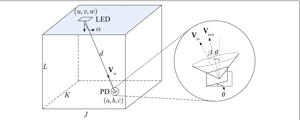
Consider a classic indoor VLC system with a single LED and a single PD, as depicted in Fig. 1. The room size is set to beJ×K×L. The LED is employed as the trans-mitter, which is fixed on the center of the ceiling. The position of the LED is supposed to be [u,v,w]. The PD as the receiver is deployed on a horizontal plane, whose posi-tion is assumed to be [a,b,c]. The PD can move to any place of the receiver plane and can change its direction by tilting a proper angle.
3.1 Transmitter
At the transmitter, the emitted instantaneous optical intensity signal by the LED is denoted asX, and the aver-age optical intensity of the LED is denoted asP. Without loss of generality, an intensity modulation scheme, OOK modulation, is employed. We assume thatXis equal prob-ably generated from the OOK modulation constellation, and thusXbelongs to the following set
X∈ {0, 2P} (1)
3.2 Channel model
For indoor VLC, the channel gain can be modeled by the Lambertian emission [22]
h= (m+1)A 2πd2 cos
m(α)cos(β) (2)
wherem = −ln 2/lncos1/2
is order of the Lamber-tian emission, and 1/2 is the semi-angle at half power
of the LED.Ais the physical area of the receiver.dis the transceiver distance.αis the irradiance angle of the LED, whileβis the incidence angle of the PD. Note that both the optical filter gain and the concentrator gain of the PD are
set to be one, and thus they are omitted in (2). Moreover,h in VLC is non-negative and real, and thusα,β∈[ 0,π/2].
According to Fig.1, the geometrical relationship of the transceiver is given by
cos(α)= w−c
d (3)
DefineVrs as the vector pointing from the receiver to
the transmitter, andVnoras the unit normal vector of the
receiver plane. Consequently, we have
cos(β)= Vnor,Vrs
Vnor · Vrs
(4)
where·,·represents the inner product operator, and· represents the norm operator.
In this paper, assume that the position of the PD is not changed by tilting the receiver plane. Therefore, Vrs =
[u−a,v−b,w−c],Vnor=[ cosϕsinθ, sinϕsinθ, cosθ],
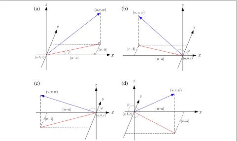
where θ and ϕ are the tilting angle of the PD and the azimuth angle. The tilting angle and the azimuth angle are shown in Figs.1and2, respectively. Assume that the pro-jection of the LED onto the XY plane is located in thei-th quadrant, andϕcan be expressed as [21]
ϕ=
⎧ ⎪ ⎪ ⎪ ⎪ ⎪ ⎪ ⎨ ⎪ ⎪ ⎪ ⎪ ⎪ ⎪ ⎩
arctanuv−−ba, i=1
π−arctanuv−−ba, i=2
π+arctanuv−−ba, i=3 2π−arctanuv−−ba, i=4
(5)
Furthermore, (4) can be written as
cos(β)=[(u−a)cosϕsinθ+(v−b)sinϕsinθ
+(w−c)cosθ]/d (6)
Substituting (3) and (6) into (2), the channel gain can be further expressed as
h=(m+1)A(w−c) m
2πdm+3 [(u−a)cosϕsinθ
+(v−b)sinϕsinθ+(w−c)cosθ]
(7)
where d = (u−a)2+(v−b)2+(w−c)2. As can be
seen in (7), when the positions of the LED and PD are fixed, the parameters a,b,c,u,v and w are constants. Moreover, according to (5), the azimuth angle ϕ is also a constant. This indicates that given the positions of the LED and PD, the channel gainhis a function of the tilting angleθ.
(a)
(b)
(c)
(d)
Fig. 2The azimuth angle when LED’s projection locates in different quadrants of the XY plane.a1st quadrant.b2nd quadrant.c3rd quadrant.
3.3 Receiver
At the receiver, the corrupted noises include thermal noise, amplifier noise, and shot noise. All of them can be modeled by Gaussian distributions [23]. However, the first two noises are independent of the input signal, while the shot noise depends on the input signal [16, 17]. So, the received electrical signalYat the PD is given by
Y=rhX+√rhXZ1+Z0 (8)
where r is the optoelectronic conversion factor of the PD. Z0 ∼ (0,σ2) and Z1 ∼ (0,ς2σ2) are the
input-independent noise, and the input-dependent noise, respectively.ς2≥0 is the scaling factor.
4 BER analysis
In wireless communications, BER is one of the commonly used indicators to reflect the system performance. Here, the BER and the optimal detection threshold for the con-sidered VLC system will be investigated. Moreover, the behavior of the derived expressions will also be analyzed.
4.1 Derivations of BER and optimal detection threshold From (7), it can be seen that his fixed when the coor-dinates of LED and PD are pre-given. When OOK is employed, the BER for VLC can be expressed as [24]
BER=Pr(off)Pr(on|off)+Pr(on)Pr(off|on) (9)
where Pr(off) =Pr(on) =1/2. In the following, the con-ditional error probabilities Pr(on|off)and Pr(off|on)will be analyzed, respectively.
According to (8), conditioned on X, Y is a Gaussian distribution. Therefore, the conditional probability den-sity function (PDF)fY|X(y|x)is obtained as
fY|X(y|x)=
1
2π(1+rhxς2)σexp
− (y−rhx)2
2(1+rhxς2)σ2
(10)
In this case, the detection threshold at the receiver is assumed to beη, which can be an arbitrary real number. Letχ=2rhP, and then Pr(off|on)can be derived as
Pr(off|on) = η
−∞
e− (y−χ)2 2(1+χς2)σ2 2π(1+χς2)σdy
= Q
χ−η
1+χς2σ
(11)
whereQ(x)=x∞e−t2/2/√2πdt. Similarly, Pr(on|off)can be derived as
Pr(on|off) = ∞
η
1
√
2πσe
−y2 2σ2dy
= Qη
σ
(12)
Because Pr(on)=Pr(off)=0.5, (9) can be written as
BERς2>0= 1 2
Q
χ−η
1+χς2σ
+Qη
σ
(13)
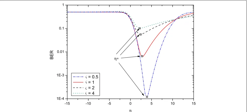
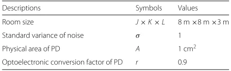
In (13), the BER is a function of η. Figure 3 shows the value of BER versus η with different ς when r = 0.9,
(a,b,c)=(2 m, 2 m, 1.5 m),(u,v,w)=(2.5 m, 2.5 m, 3 m), P = 55 dBm andσ = 1. It can be observed that for a
givenς, the BER curve has a peak value and a valley value. As it is well known, the optimum detection thresholdη∗ corresponds to the valley value of BER. By analyzing (13), the following theorem is obtained.
Theorem 1For the system model in (8), the optimal detection thresholdη∗whenς >0is given by
η∗=
1+χς2+ς2σ2(1+χς2)ln(1+χς2)
χ −1
ς2 (14)
ProofSee Appendix1.
Substituting (14) into (13), the BER whenς2>0 can be finally written as
BERς2>0= 1 2 ⎡ ⎢ ⎣Q
⎛ ⎜ ⎝ 1+χς
2−1+ς2σ2ln(1+χς2)
χ ς2σ
⎞ ⎟ ⎠
+ Q
⎛ ⎜ ⎝
1+χς2+ς2σ2(1+χς2)ln(1+χς2)
χ −1
ς2σ
⎞ ⎟ ⎠ ⎤ ⎥ ⎦ (15)
4.2 Behavior analysis
By analyzingTheorem1, the changing trend ofη∗withς can be obtained in the following theorem.
Theorem 2When χ is very small, the value ofη∗ in (14) increases with the increase of ς. However, when χ
is very large, the value ofη∗ in (14) decreases with the increase ofς.
ProofSee Appendix2.
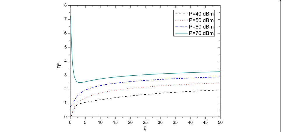
InTheorem1, it can be seen thatη∗is a function ofς. To show the relationship betweenη∗andς, Fig.4shows the value ofη∗versus ς with differentPwhenr = 0.9, h = 8.335×10⁻⁷, andσ = 1. As is observed, whenP is small, the value ofη∗increases with the increase ofς. However, whenPis large, the value ofη∗decreases with
ς. This result also verifies the correctness ofTheorem2. By analyzing (15), the asymptotic behavior of the BER is derived in the following theorem.
Theorem 3The asymptotic behavior of the BER in (15) is given by
lim
ς→0BERς2>0=BERς2=0=Q
χ 2σ
(16)
ProofSee Appendix3.
It can be known fromTheorem 3 that whenς → 0, the VLC system with input-dependent noise achieves the same BER performance as the VLC system with only input-independent noise (i.e., ς = 0). In this paper, Eq. (16) can be used as a benchmark.
5 Problem formulation and solving
In the above section, the BER has been analyzed for the indoor VLC. In this section, an optimization problem to
minimize the BER will be investigated. By using the prin-ciple of convex optimization, the optimization problem is effectively solved. Finally, the implementation of the optimal tilting angle is discussed.
5.1 Problem formulation
The objective of the paper is to minimize the BER of the VLC system. According to the relative positions of LED and PD, the tilting angleθ can not exceedπ/2, i.e.,θ ∈ [ 0,π/2]. Therefore, the optimization problem is given by
min following theorem can be derived.
Theorem 4For all fixed ς2 ≥ 0, the BER for the VLC system is a monotonously decreasing function with h.
ProofSee Appendix4.
By usingTheorem4, problem (17) can be transformed to max
θ h
s.t. 0≤θ ≤π/2 (18)
where the channel gainhis given by (7). By analyzing (7), the following theorem can be obtained.
Theorem 5The objection function h in problem (18) is a concave function ofθ.
ProofSee Appendix5.
By usingTheorem5, the maximum value ofhis achieved by letting the first-order partial derivative ofhwithθto be zero, i.e.,
Therefore, the optimal tilting angleθ∗is obtained as
θ∗=arctan (a−u)
2+(b−v)2
|w−c|
(20)
5.3 Implementation of the tilting angle
From (20), it can be found that the optimal tilting angle is a function of the positions of the LED and the PD. In this paper, the position of the LED (i.e., [u,v,w]) is fixed, but the position of the PD (i.e., [a,b,c]) is variable. Therefore,
to realize the angle tilting of the receiver plane, the first step is to determine the position of the PD. With an arbi-trary tilting angle larger than zero, the tilted receiver can obtain its position by using the three-dimensional posi-tioning method proposed in our previous work [25]. After obtaining the position of the PD, the optimal tilting angle for the receiver can be calculated by using (20). Finally, according to the optimal tilting angle, the receiver can realize the angle tilting by employing an electrical machin-ery. The electrical machinery first makes the tilting angle to be zero and then increases the tilting angle until the optical tilting angle is achieved.
6 Numerical results and discussion
In this section, a practical VLC system in a room is consid-ered as the test system. The derived theoretical expression of the BER will be confirmed by using the Monte-Carlo simulations in MATLAB. Note that the simulation results presented in this section are the average of N = 106 independent trials. The detailed simulation process is pro-vided in Algorithm 1. Moreover, the main simulation parameters are illustrated in Table1.
Algorithm 1:The simulation process for BER.
1 Initialize the system parameters, and lett=0,n=0,
N=106.
2 While(t≤N)do
3 Compute the channel gainhby using (7). 4 Randomly generate an OOK modulated signal
X=P∗(rand(1, 1) >0.5).
5 Generate a random numberZ1for the
input-dependent noise, which followsN(0,ς2σ2).
6 Generate a random numberZ0for the
input-independent noise, which followsN(0,σ2).
7 Computey=rhX+√rhXZ1+Z0.
8 Compute the optimal detection thresholdη∗by
using (14).
Table 1Main simulation parameters
Descriptions Symbols Values
Room size J×K×L 8 m×8 m×3 m
Standard variance of noise σ 1
Physical area of PD A 1 cm2
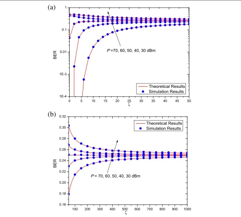
Figure 5 shows the BER versus ς for different trans-mit optical powersP. In the simulation, [u,v,w]=[2.5 m, 2.5 m, 3 m] and [a,b,c]=[2 m, 2 m, 1.5 m]. The tilting angle of the PD is set to be zero. The order of the Lam-bertian emissionm = 5. It can be seen from the figure that, whenPis small, the BER performance improves with the increase of ς. However, when P is large, the value of the BER increases asς. This indicates that the BER performance is strongly effected by the value ofς. More-over, whenςtends to a large value, the value of the BER trends to a stable value (i.e., 0.25). From Fig. 5, for a fixedς, the BER performance improves with the increase of P. As is known, large optical power will generate a high SNR at receiver, and thus it will result in good BER performance. Furthermore, the theoretical results match
exactly with the simulation results. This indicates that the derived BER expression can be used to evaluate the system performance without time-intensive simulations.
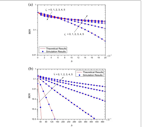
Figure6shows the BER versus the channel gainhwith differentς. In this simulation, the transmit optical power of the LED is P = 50 dBm. As can be observed, with the increase ofh, the BER performance improves accord-ingly, which coincides with Theorem 4. Moreover, for small value of h as shown in Fig. 6a, the BER perfor-mance improves with the increase ofς. However, for large value of h as shown in Fig. 6b‘, the BER performance degrades with the increase of the ς. This conclusion is similar to that in Fig. 5. Once again, it should be noted that the theoretical results match well to the simulation results.
(a)
(b)
(a)
(b)
Fig. 6BER versus channel gainhwith differentςwhenP=50 dBm.aBER with smallh,bBER with largeh
Figure7shows the channel gainhversus the semi-angle at half power of the LED 1/2 before and after tilting
the receiver plane. In the simulation, the average opti-cal powerPis set to be 50 dBm, and the coordinates of LED and PD are set to be [2.5 m, 2.5 m, 3 m] and [0 m, 0 m, 0 m], respectively. It can be observed that, as the increase of1/2, both the two curves increase first and
then decrease a little. When 1/2 = 550, the channel
gains of the two curves achieve the maximum values. In addition, by tilting the receiver plane, the channel gain performance improves dramatically. This means that it is necessary to tilt the receiver plane properly to enhance system performance.
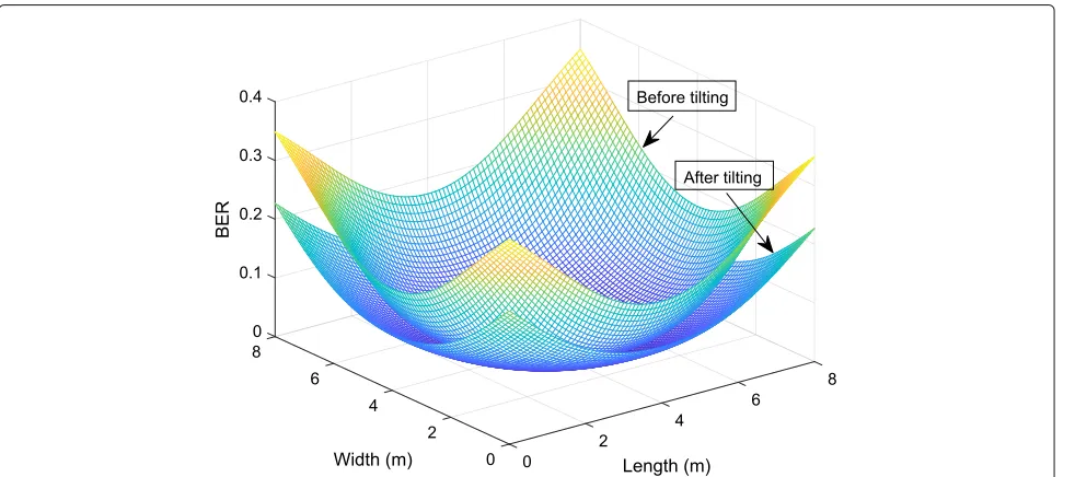
Figure8plots the distributions of the BER before and after tilting the receiver plane in the room. It can be
observed that the worst BER achieves when the PD is located in the corner, while the best BER obtains when the PD is located in the center of the floor. This is n because large transmission distance will result in the system per-formance degradation. Moreover, the BER perper-formance improves in the whole room after tilting the receiver plane. Specifically, when the PD is located in the corner, the value of the BER reduces from 0.3487 to 0.2270 after tilting the receiver plane. This indicates that it is necessary to tilt the receiver plane properly in VLC system.
Fig. 7Channel gainhversus the semi-angle at half power of the LED1/2
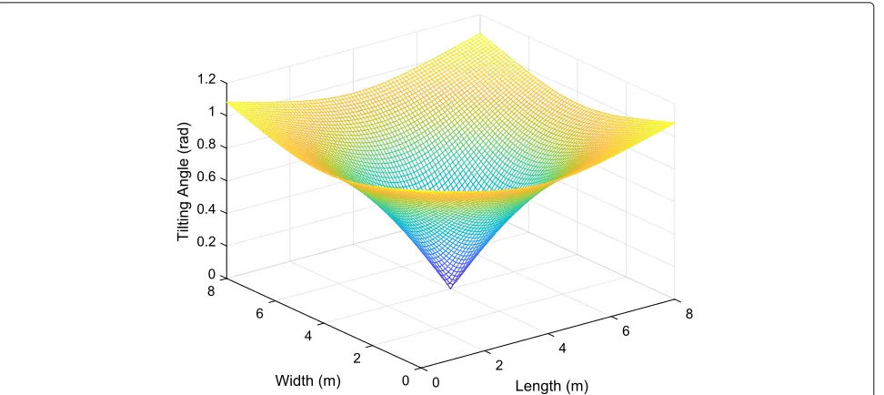
the receiver plane, the distance between the transceiver achieves the minimum value, and the tilting angle of the PD in this case is zero. When the PD moves from the center of the receiver plane to other place, the tilting angle of the PD increases gradually. When the PD is located in the corner of the receiver plane, the tilting angle of the PD gets its maximum value, i.e., 1.8032 rad. Therefore, the tilting angle provided in this figure can provide some insights for practical system design.
7 Conclusions
This paper focuses on an VLC system with input-dependent noise. The main conclusions of this paper are listed as follows:
• For the VLC system with input-dependent noise, the optimal detection threshold is obtained. Also, the theoretical expression of the BER is derived, which is quite accurate to evaluate the system performance.
Fig. 9Tilting angle distributions after tilting the receiver plane in the room
• The system performance is strongly affected by the input-dependent noise. For smallh or P, the BER decreases with the increase ofς. However, for largeh orP, the trend of the BER curve changes. Moreover, the larger the value of the channel gain is, the better the BER performance becomes.
• When the transceiver distance is large, the BER performance can be dramatically enhanced by tilting the receiver plane. In practice, the suggested tilting angle of the receiver place is shown in Fig.9.
8 Appendix 1: Proof of Theorem1
To obtain the optimum detection threshold, taking the first-order partial derivative ofBERς2>0with respect toη and letting it to be zero, we have
∂BERς2>0 ∂η =
1 2√2πσ
⎡ ⎢ ⎣e
−2(1(χ+χς−η)22)σ2
1+χς2 −e
−2ησ22
⎤ ⎥
⎦=0 (21)
i.e.,
χς2
1+χς2η
2+ 2χ
1+χς2η−
χ2
1+χς2
−σ2ln1+χς2=0
(22)
By solving the quadratic Eq. (22), we have
η=−1±
1+χς2+ς2σ2(1+χς2)ln(1+χς2)
χ
ς2 (23)
According to the curve of BER in Fig. 3, the optimum detection threshold (14) is obtained.
9 Appendix 2: Proof of Theorem2
Case (a): Whenχis very small, we have
η∗≈ 1+ς4σ2−1
ς2 (24)
Taking the first-order derivative of η∗ with respect toς, we have
d dς
1+ς4σ2−1
ς2
= 2 1+ς
4σ2−1
ς3 1+ς4σ2 >0
(25)
This indicates that whenχis small, the value ofη∗rises with the increase ofς.
Case (b): Whenχis very large, we have
η∗≈ χ+ς2σς2ln(χς2) (26)
Taking the first-order derivative of η∗ with respect toς, we have
d dς
χ+ς2σ2lnχς2
ς =
ς2σ2−χ
ς2χ+ς2σ2lnχς2<
0
(27)
10 Appendix 3: Proof of Theorem3 the input-independent noise. Under this circumstance, (8) reduces to Y = rhX + Z0. According to Theorem 1,
the optimum detection threshold in this case can be eas-ily derived asη∗ = χ/2. Moreover, the conditional PDF fY|X(y|x)becomes
Therefore, the BER becomes
BERς2=0=
11 Appendix 4: Proof of Theorem4
DefineI1andI2as
InI1, taking the first-order partial derivative ofI4with
h, we can get
Then, taking the first-order partial derivative ofI5withh,
we can get
which indicates thatI5is a monotonously decreasing
func-tion ofh. Whenh→0,I5→0. Sinceh>0,I5<0 always
holds. Moreover, according to (34), we have∂I4/∂h ≤
0, which means that I4 is a monotonously decreasing
function of h. Moreover, I3 is a monotonously
increas-ing function ofh. Given the above,I1is a monotonously
increasing function ofh.
Furthermore, taking the first-order partial derivative of I2withh, we have
where the inequality follows because x > ln(1 + x) always holds for all x > 0. Therefore, I2 is also a
monotonously increasing function ofh. Moreover,Q(·)is a monotonously decreasing function. Therefore, BERς2>0 is a monotonously decreasing function ofh, i.e.,
∂BERς2>0
∂h <0 (37)
Similarly, when ς2 = 0, taking the first-order partial
derivative of BERς2=0with respect tohin (16), we have 12 Appendix 5: Proof of Theorem5
By taking the second-order partial derivative ofhwithθ, we get
Abbreviations
ACO: Asymmetrically clipped optical; BER: Bit error rate; CSK: Color shift keying; DCO: Direct current optical; GSSK: Generalized space shift keying; LEDs: Light-emitting diodes; OFDM: Orthogonal frequency division multiplexing; OOK: On-off keying; PD: Photodiodes; SNR: Signal-to-noise ratio; VLC: Visible light communication
Acknowledgements
The research presented in this paper was supported by Huaiyin Institute of Technology, China.
Funding
This paper is supported by National Natural Science Foundation of China (61701254), Natural Science Foundation of Jiangsu Province (BK20170901), Key International Cooperation Research Project (61720106003), the open fund for Jiangsu key laboratory of traffic and transportation security, Huaiyin Institute of Technology (TTS2017-03), the Open Research Fund of the Key Laboratory of Broadband Wireless Communication and Sensor Network Technology, Nanjing University of Posts and Telecommunications, the Ministry of Education (JZNY201706), NUPTSF (NY216009), the Open Research Fund of the Key Laboratory of Intelligent Computing & Signal Processing, Anhui University, and the Open Research Subject of the Key Laboratory (Research Base) of Signal and Information Processing, Xihua University (szjj2017-047).
Availability of data and materials
The authors declare that all the data and materials in this manuscript are available.
Authors’ contributions
SHL is the main contributor of the paper. She proposes the main idea, derives the expression of BER, and solves the optimization problem. CL helps to finish the simulation results. XB and JYW help to polish the content of the paper. All authors read and approve the final manuscript.
Authors’ information
Sheng-Hong Lin is working toward her PhD degree at Nanjing University of Posts and Telecommunications, Nanjing, China. Her research interest is visible light communications.
Cheng Liu is currently studying for the M.S. degree from the National Mobile Communications Research Laboratory, Southeast University, Nanjing, China. His research interest is physical-layer security in visible light communications. Xu Bao is currently a professor at Jiangsu Key Laboratory of Traffic and Transportation Security, Huaiyin Institute of Technology, Huai’an, China. His research interest is visible light communications.
Jin-Yuan Wang is currently a lecturer at College of Telecommunications and Information Engineering, Nanjing University of Posts and Telecommunications, Nanjing, China. His current research interest is visible light communications.
Competing interests
The authors declare that they have no competing interests.
Publisher’s Note
Springer Nature remains neutral with regard to jurisdictional claims in published maps and institutional affiliations.
Author details
1Jiangsu Key Laboratory of Traffic and Transportation Security, Huaiyin Institute of Technology, 223003 Huaian, China.2Key Lab of Broadband Wireless Communication and Sensor Network Technology, Nanjing University of Posts and Telecommunications, 210003 Nanjing, China.3National Mobile Communications Research Laboratory, Southeast University, 211111 Nanjing, China.
Received: 22 May 2018 Accepted: 5 September 2018
References
1. P. H. Rathak, X. Feng, P. Hu, P. Mohapatra, Visible light communication, networking and sensing: a survey, potential and challenges. IEEE Commun. Surv. & Tutorials.17(4), 2047–2076 (2015)
2. H. Hass, L. Yin, Y. Wang, C. Chen, What is LiFi? IEEE/OSA J. Lightwave Technol.34(6), 1533–1544 (2016)
3. C. P. Li, Y.ing. Yi, K. S. Lee, Performance analysis of visible light communication using the STBC-OFDM technique for intelligent transportation systems. Int. J. Electron.101(8), 1117–1133 (2014) 4. R. M. Mare, C. Luiz Marte, C. E. Cugnasca, Visible light communication
applied to intelligent transport systems: an overview. IEEE Lat. Am. Trans. 14(7), 3199–3207 (2016)
5. T. Komine, M. Nakagawa, Fundamental analysis for visible-light communication system using LED lights. IEEE Trans. Consum. Electron. 50(1), 100–107 (2004)
6. J. B. Wang, Q. S. Hu, J. Wang, M. Chen, J. Y. Wang, Tight bounds on channel capacity for dimmable visible light communications. IEEE/OSA J. Lightwave Technol.31(23), 3771–3779 (2013)
7. R. Jiang, Z. Wang, Q. Wang, L. Dai, A tight upper bound on channel capacity for visible light communications. IEEE Commun. Lett.20(1), 97–100 (2016)
8. K. I.1. Ahn, J. K. Kwon, Capacity analysis of M-PAM inverse source coding in visible light communications. IEEE/OSA J. Lightwave Technol.30(10), 1399–1404 (2012)
9. X. Li, J. Vucic, V. Jungnickel, J. Armstrong, On the capacity of
intensity-modulated direct-detection systems and the information rate of ACO-OFDM for indoor optical wireless applications. IEEE Trans. Commun. 60(3), 799–809 (2012)
10. C. P. Li, Y.ing. Yi, K. S. Lee, Pilot self-coding applied in optical OFDM systems. Int. J. Electron.102(4), 548–562 (2015)
11. L. Jia, J. Y. Wang, W. Zhang, M. Chen, J. B. Wang, Symbol error rate analysis for colour-shift keying modulation in visible light communication system with RGB light-emitting diodes. IET Optoelectron.9(5), 199–206 (2015) 12. W. O. Popoola, E. Poves, H. Haas, Error performance of generalised space
shift keying for indoor visible light communications. IEEE Trans. Commun. 61(5), 1968–1976 (2013)
13. Y. Yi, C. P. Li, K. S. Lee, Optimum spread code applied in indoor visible light data transmission for optical multipath dispersion reduction. IETE Techn. Rev.30(3), 233–239 (2013)
14. Y. Yi, C. P. Li, K. S. Lee, Adaptive MMSE equalizer for optical multipath dispersion in indoor visible light communication. IETE J. Res.58(5), 347–355 (2012)
15. J. Katz, Detectors for optical communications: A review. Adv. Mater.5(1), 21–38 (1983)
16. J. Y. Wang, J. B. Wang, M. Chen, J. Wang, inIEEE Global Communications Conference. Capacity bounds for dimmable visible light communications using PIN photodiodes with input-dependent Gaussian noise (IEEE, Austin, 2014), pp. 1–6
17. J. Y. Wang, Z. Yang, Y. Wang, M. Chen, On the performance of spatial modulation based optical wireless communications. IEEE Photon. Technol. Lett.28(19), 2094–2097 (2016)
18. M. F. Keskin, S. Gezici, Comparative theoretical analysis of distance estimation in visible light positioning systems. IEEE/OSA J. Lightwave Technol.34(3), 854–865 (2016)
19. K. Xu, H. Yu, Y. J. Zhu, Channel-adpted spatial modulation for massive MIMO visible light communications. IEEE Photon. Technol. Lett.28(23), 2693–2696 (2016)
20. W. Xu, J. Wang, H. Shen, H. Zhang, X. You, Indoor positioning for multiphotodiode device using visible-light communications. IEEE Photon. J.8(1), 1–11 (2016)
21. Z. Wang, C. Yu, W. D. Zhong, J. Chen, Performance improvement by tilting receiver plane in M-QAM OFDM visible light communications. Opt. Exp. 19(14), 13418–13427 (2011)
22. J. Y. Wang, J. Dai, R. Guan, L. Jia, Y. Wang, M. Chen, Channel capacity and receiver deployment optimization for multi-input multi-output visible light communications. Opt. Exp.24(12), 1–15 (2016)
23. A. Lapidoth, S. M. Moser, M. A. Wigger, On the capacity of free-space optical intensity channels. IEEE Trans. Inf. Theory.55(10), 4449–4461 (2009) 24. S. M. Navidpour, M. Uysal, M. Kavehrad, BER performance of free-space
optical transmission with spatial diversity. IEEE Trans. Wirel. Commun. 6(8), 2813–2819 (2007)