ISSN: 2319-8753
I
nternational
J
ournal of
I
nnovative
R
esearch in
S
cience,
E
ngineering and
T
echnology
(An ISO 3297: 2007 Certified Organization)
Vol. 2, Issue 8, August 2013
Copyright to IJIRSET www.ijirset.com 4101
PERFORMANCE ANALYSIS AND
MATERIAL OPTIMIZATION OF DISC
BRAKE USING MMC
Yathish K.O
1, Arun L.R
2, Kuldeep B
3, Muthanna K.P
4P.G. Scholar, Department of Mechanical Engineering, The Oxford college of Engineering , Karnataka, India1,3,4 Associate Professor, Department of Mechanical Engineering, The Oxford college of Engineering, Karnataka, India2
Abstract: In automotive field lots of studies are going on to conventional materials with the composites. Hence to reduce weight, Aluminium based metal matrix composite (MMC) found to be the best alternative for this. The motive of this study is to analyse the performance of disc brake for different materials (Cast iron & Aluminium6061-SiC-red mud composite) under same working conditions/parameters. And the material impact on displacement, stress, contact pressure, contact status, contact sliding distance of disc and pad assembly are obtained using software packages like ANSYS (14.5) and hypermesh.
Keywords: Disc brake, ANSYS, composite, silicon carbide, red mud.
I. INTRODUCTION
A disc brake is a wheel brake which slows rotation of the wheel by the friction caused by pushing brake pads against a brake disc with a set of calipers. The brake disc (or rotor in American English) is usually made of cast iron, but may in some cases be made of composites such as reinforced carbon–carbon or ceramic matrix composites. This is connected to the wheel and/or the axle. To stop the wheel, friction material in the form of brake pads, mounted on a device called a brake caliper, is forced mechanically, hydraulically, pneumatically or electromagnetically against both sides of the disc. Friction causes the disc and attached wheel to slow or stop. Brakes convert motion to heat, and if the brakes get too hot, they become less effective, a phenomenon known as brake fade.
Disc brakes are widely used on cars because of their better heat dissipation ability; a direct result of the exposed friction surface. The friction surface of a drum brake is inside and heat dissipation relies upon heat being conducted through the drum so car manufacturers fit drum brakes only on the rear axle of “low” performance cars. Additionally a drum brake provides a very effective parking brake. In commercial vehicles, drum brakes are still widely used across the world, being robust, durable and easy to maintain but in Europe most heavy goods vehicles now use disc brakes. Furthermore, the performance requirement is not just for one isolated brake application, but for a series of high deceleration brake applications which form the part of the performance assessment known as the „fade‟ test. So, the front brakes of a typical passenger car have to be designed to provide large amounts of braking torque, and withstand large amounts of heat generated, heat transfer, high temperatures and thermal loading.
ISSN: 2319-8753
I
nternational
J
ournal of
I
nnovative
R
esearch in
S
cience,
E
ngineering and
T
echnology
(An ISO 3297: 2007 Certified Organization)
Vol. 2, Issue 8, August 2013
Copyright to IJIRSET www.ijirset.com 4102
V.M.M.Thilak [2] et al, made an attempt to investigate the suitable hybrid composite material which is lighter than cast iron and has good Young’s modulus, Yield strength and density properties. Aluminum base metal matrix composite and High Strength Glass Fiber composites have a promising friction and wear behavior as a Disk brake rotor. The transient thermo elastic analysis of Disc brakes in repeated brake applications has been performed and the results were compared. The suitable material for the braking operation is S2 glass fiber and all the values obtained from the analysis are less than their allowable values. Hence the brake Disc design is safe based on the strength and rigidity criteria. By identifying the true design features, the extended service life and long term stability is assured.
M.A. Maleque [3] et al, the widely used brake rotor material is cast iron which consumes much fuel due to its high specific gravity. The aim of this paper is to develop the material selection method and select the optimum material for the application of brake disc system emphasizing on the substitution of this cast iron by any other lightweight material. Material performance requirements were analyzed and alternative solutions were evaluated among cast iron, aluminium alloy, titanium alloy, ceramics and composites. Mechanical properties including compressive strength, friction coefficient, wear resistance, thermal conductivity and specific gravity as well as cost, were used as the key parameters in the material selection stages. The analysis led to aluminium metal matrix composite as the most appropriate material for brake disc system.
II. ANALYSIS OF DISC BRAKE
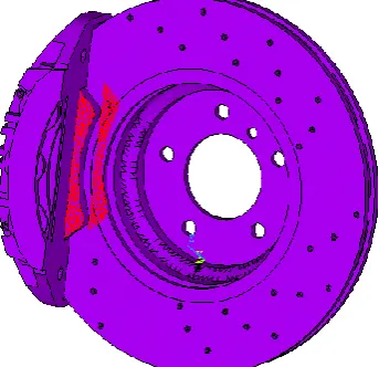
Fig.1: Disc Brake model
Fig.2: Meshed Model of Disc Brake
ISSN: 2319-8753
I
nternational
J
ournal of
I
nnovative
R
esearch in
S
cience,
E
ngineering and
T
echnology
(An ISO 3297: 2007 Certified Organization)
Vol. 2, Issue 8, August 2013
Copyright to IJIRSET www.ijirset.com 4103
Number of Nodes : 222898 Number of Elements : 129716
Table 1
Material properties used for analysis
Sl no Parameters Material 1 (cast iron) Material 2 (Al6061-3%SiC-9% red mud)
1 Youngs modulus (GPa) 16.9e-3 73e-3
2 Poisson’s ratio 0.275 0.22
3 Density (g/mm3) 7.1e-3 2.85e-3
Loads and constraints:
Fig.3: All DOF constrained at mount position like bolt holes and in uz, ux direction for brake pad.
Fig.4: Pressure applied at the inner surface of the brake pad.
III. RESULTS AND DISCUSSION
ANALYSIS
ISSN: 2319-8753
I
nternational
J
ournal of
I
nnovative
R
esearch in
S
cience,
E
ngineering and
T
echnology
(An ISO 3297: 2007 Certified Organization)
Vol. 2, Issue 8, August 2013
Copyright to IJIRSET www.ijirset.com 4104
Table 2 & 3 COMPARISON OF RESULTS FOR DIFFERENT MATERIALS.
Sl
no Material
100 RPS Stress (MPa) Displacement (mm) Contact
sliding (mm) Contact pressure (MPa)
1 Old material (cast iron) 21.844 0.422e-3 0.505e-4 8.082
2 New material (Al6061-3%
SiC-9% red mud) 8.384 0.110e-3 0.124e-4 7.684 3 Percentage difference 61.62 73.93 75.44 4.92
Sl
no Material
150 RPS Stress (MPa) Displacement (mm) Contact
sliding (mm) Contact pressure (MPa)
1 Old material (cast iron) 131.454 0.001167 0.186e-3 8.976 2 New material (Al6061-3%
SiC-9% red mud) 50.615 0.979e-3 0.159e-3 8.168 3 Percentage difference 61.49 16.11 14.52 9.0
1.STRESS PLOTS
For 100 RPS
Fig.5: Stress contour for 100RPS, cast iron material Fig.6: Stress contour for 100RPS, Al6061-3% SiC-9% red mud material
For 150 RPS
ISSN: 2319-8753
I
nternational
J
ournal of
I
nnovative
R
esearch in
S
cience,
E
ngineering and
T
echnology
(An ISO 3297: 2007 Certified Organization)
Vol. 2, Issue 8, August 2013
Copyright to IJIRSET www.ijirset.com 4105
5.7.2 DISPLACEMENT
For 100 RPS
Fig.9: Displacement contour for 100RPS, Fig.10: Displacement contour for 100RPS, cast iron material Al6061-3% SiC-9% red mud material
For 150 RPS
Fig.11: Displacement contour for 150RPS, Fig.12: Displacement contour for 150RPS, cast iron material Al6061-3% SiC-9% red mud material
5.7.3 CONTACT SLIDING
ISSN: 2319-8753
I
nternational
J
ournal of
I
nnovative
R
esearch in
S
cience,
E
ngineering and
T
echnology
(An ISO 3297: 2007 Certified Organization)
Vol. 2, Issue 8, August 2013
Copyright to IJIRSET www.ijirset.com 4106
Fig.13: Contact sliding contour for 100RPS, Fig.14: Contact sliding contour for 100RPS, cast iron material Al6061-3% SiC-9% red mud material
For 150 RPS
Fig.15: Contact sliding contour for 150RPS, Fig.16: Contact sliding contour for 150RPS, cast iron material Al6061-3% SiC-9% red mud material
5.7.4 CONTACT PRESSURE
ISSN: 2319-8753
I
nternational
J
ournal of
I
nnovative
R
esearch in
S
cience,
E
ngineering and
T
echnology
(An ISO 3297: 2007 Certified Organization)
Vol. 2, Issue 8, August 2013
Copyright to IJIRSET www.ijirset.com 4107
Fig.17: Contact pressure contour for 100RPS, Fig.18: Contact pressure contour for 100RPS, cast iron material Al6061-3% SiC-9% red mud material
For 150 RPS
Fig.19: Contact pressure contour for 150RPS, Fig.20: Contact pressure contour for 150RPS, cast iron material Al6061-3% SiC-9% red mud material
5.7.5 CONTACT STATUS
For 100 RPS
ISSN: 2319-8753
I
nternational
J
ournal of
I
nnovative
R
esearch in
S
cience,
E
ngineering and
T
echnology
(An ISO 3297: 2007 Certified Organization)
Vol. 2, Issue 8, August 2013
Copyright to IJIRSET www.ijirset.com 4108
For 150 RPS
Fig.23: Contact status contour for 150RPS, Fig.24: Contact status contour for 150RPS, cast iron material Al6061-3% SiC-9% red mud material
IV. CONCLUSION
The stress developed in the disc brake is comparatively less in the material 2 compared to the former (material 1).
The displacement reduces with the change of material (material2).
Contact sliding, contact pressure decreases with the material change (material 2).
Contact status will be more in the material 2.
REFERENCES
[1] Ameer Fareed Basha Shaik1, Ch.Lakshmi Srinivas., STRUCTURAL AND THERMAL ANALYSIS OF DISC BRAKE WITH AND WITHOUT CROSSDRILLED ROTAR OF RACE CAR, International Journal of Advanced Engineering Research and Studies, Vol. I/ Issue IV/July-Sept., 2012/39-43, India
[2] V.M.M.Thilak, R.Krishnaraj, Dr.M.Sakthivel, K.Kanthavel, Deepan Marudachalam M.G, R.Palani. TRANSIENT THERMAL AND STRUCTURAL ANALYSIS OF THE ROTOR DISC OF DISC BRAKE. International Journal of Scientific & Engineering Research Volume 2, Issue 8, August-2011. India.