ABSTRACT
PANCHAMUKHI, SHRINIVAS ANAND. Providing Task Isolation via TLB Coloring. (Under the direction of Dr. Frank Mueller.)
The translation look aside buffer (TLB) improves the performance of the system by caching
thevirtual page to physical frame mapping. But TLBs present a source of unpredictability for
real time systems. Standard heap allocated regions do not provide guarantees on the TLB set that will hold a particular page translation. This unpredictability can lead to TLB misses with a penalty of thousands of cycles and consequently intertask interference resulting in loose bounds on the worst case execution time (WCET).
In this paper, we design and implement a new heap allocator that guarantees the TLB set that will hold a particular page translation. The allocator is based on the concept of page
coloring. Virtual pages are colored such that two pages of different color cannot map to the
same TLB set.
©Copyright 2014 by Shrinivas Anand Panchamukhi
Providing Task Isolation via TLB Coloring
by
Shrinivas Anand Panchamukhi
A thesis submitted to the Graduate Faculty of North Carolina State University
in partial fulfillment of the requirements for the Degree of
Master of Science
Computer Science
Raleigh, North Carolina 2014
APPROVED BY:
Dr. William Enck Dr. Alexander Dean
DEDICATION
BIOGRAPHY
ACKNOWLEDGEMENTS
TABLE OF CONTENTS
LIST OF TABLES . . . vi
LIST OF FIGURES . . . vii
Chapter 1 Introduction . . . 1
Chapter 2 Motivation, Hypothesis and Contribution . . . 3
2.1 Motivation . . . 3
2.2 Hypothesis . . . 4
2.3 Contributions . . . 4
Chapter 3 Design . . . 5
Chapter 4 Implementation . . . 8
4.0.1 Notations . . . 8
4.0.2 Data structures . . . 9
4.0.3 Generic algorithms . . . 9
4.0.4 Intel Xeon E-2650 . . . 11
Chapter 5 Experimental framework . . . 13
Chapter 6 Results . . . 15
6.0.5 Predictability . . . 15
6.0.6 Identifying noisy DTLB sets . . . 16
6.0.7 L1/L2 DTLB miss penalty . . . 17
6.0.8 Synthetic benchmarks . . . 17
6.0.9 Malardalen benchmarks . . . 23
6.0.10 Mi benchmarks . . . 26
Chapter 7 Related Work . . . 28
Chapter 8 Future Work and Conclusion . . . 30
References. . . 31
Appendix . . . 34
.1 Introduction . . . 35
Appendix A Detailed Experimental Results . . . 36
A.1 malloc vs. tlb malloc experiment . . . 36
LIST OF TABLES
LIST OF FIGURES
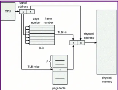
Figure 1.1 Virtual page to physical page translation using TLB . . . 1
Figure 3.1 TLB coloring - max contiguous allocation =page size . . . 5
Figure 3.2 TLB coloring - max contiguous allocation =page size×R . . . 6
Figure 4.1 tlb malloc internals . . . 8
Figure 4.2 tlb free internals . . . 9
Figure 4.3 Data structures . . . 10
Figure 6.1 DTLB set utilization . . . 16
Figure 6.2 Same set vs. diff set using tlb malloc . . . 18
Figure 6.3 Jobs vs. execution cycles for T1 . . . 19
Figure 6.4 Malloc: Jobs vs DTLB misses for T1 . . . 20
Figure 6.5 tlb malloc: Jobs vs DTLB misses for T1 . . . 20
Figure 6.6 Malloc: Jobs vs DTLB misses for T2 . . . 21
Figure 6.7 tlb malloc: Jobs vs DTLB misses for T2 . . . 21
Figure 6.8 Jobs vs execution cycles for T1 . . . 22
Figure 6.9 T1 . . . 24
Figure 6.10 T2 . . . 24
Figure 6.11 T3 . . . 25
Figure 6.12 T4 . . . 25
Figure 6.13 T1 and T2 use fft and adpcm benchmarks, respectively . . . 26
Figure 6.14 Combination of Malardalen and Mi benchmarks . . . 26
Figure A.1 Malloc: Jobs vs. DTLB misses for T1 . . . 37
Figure A.2 tlb malloc: Jobs vs DTLB misses for T1 . . . 37
Figure A.4 tlb malloc: Jobs vs DTLB misses for T2 . . . 37
Figure A.3 Malloc: Jobs vs. DTLB misses for T2 . . . 38
Figure A.5 Jobs vs. execution cycles for T1 . . . 38
Figure A.6 Jobs vs. execution cycles for T2 . . . 39
Figure A.7 Jobs vs. execution cycles T1 . . . 40
Figure A.8 Jobs vs. execution cycles for T2 . . . 40
Figure A.9 Jobs vs. execution cycles for T1 . . . 41
Figure A.10 Jobs vs. execution cycles T2 . . . 41
Figure A.11 Jobs vs. execution cycles for T1 . . . 42
Chapter 1
Introduction
The translation look aside buffer (TLB) is a hardware cache that sits close to the processor and caches the virtual page to physical frame mappings. Today’s computer architectures support multiple levels of TLBs. Most processors from Intel [9], AMD [2] and ARM [3] feature a separate instruction TLB (ITLB) and a data TLB (DTLB) at the first level. In some processors [9], the second level of the TLB is shared between data and instructions while in others [2], the DTLB is shared between different cores. Typically, a virtual address is translated to the physical address using a hierarchy of translation tables known as paging structures. Figure 1.1 shows a simple example of how a virtual page is translated to a physical frame using a TLB. In this example, on a TLB miss, the page table is consulted directly. In general, the highest-level paging structure
will be consulted.
Static timing analysis tools [19] analyze the source code of a task and compute the worst case execution time (WCET) of the task. Mueller [13] (among others) has proposed abstract cache states to analyze instruction caches to achieve tight bounds on WCET. White et al. [18], Ramaprasad et al. [15] [16] and Ferdinand et al. [7] have proposed bounding the WCET for systems with data caches. To the best of our knowledge, TLBs have not been considered in the context of achieving tight bounds on the WCET of a task.
In this thesis, we describe the design and implementation of a new heap allocator that we refer to as tlb malloc. This allocator utilizes the concept of page coloring. We assign colors to virtual pages in such a way that virtual pages with different color will not map to the same DTLB set. When tasks dynamically allocate memory usingtlb malloc, in addition to specifying the size of the allocation, they will also specify the color of the memory region. By ensuring that each task allocates memory regions of a unique color, we can provide isolation between tasks and also enable static timing analysis to potentially calculate significantly tighter bound on the WCET. Our experimental evaluations reveal the unpredictability associated with standard heap allocation. Using a set of synthetic and standard benchmarks, we show that tasks can be isolated from each other, i.e., no inter-task DTLB misses are incurred.
Past research has utilized page coloring to guarantee task isolation with respect to caches and DRAMs. Ward et al. [17] have proposed coloring physical frames such that two frames with different colors will not cause last level cache conflicts. Yun et al. [20] have proposed a DRAM bank aware memory allocation. This ensures that concurrently running applications on different cores do not access memory that maps to the same DRAM bank.
Chapter 2
Motivation, Hypothesis and
Contribution
2.1
Motivation
TLBs improve the performance of the system in terms of speeding up the page translations, but they are also a source of unpredictability for real time systems. Heap allocation is generally avoided in real time systems due to the following unpredictability issues. First, the WCET of the standard heap allocation API is too high or is unbounded [12]. Second, standard heap allocation APIs do not guarantee the DTLB set in which the virtual page to physical frame mapping will be placed. Our focus in this paper is on the latter point. This unpredictability poses three problems.
First, it makes it difficult for static timing analysis to determine whether a memory access will hit or miss in the DTLB. Hence, for calculating the WCET of a task, static timing analysis would take a pessimistic approach and calculate the WCET assuming all memory references to be a miss. This pessimistic WCET leads to inefficient processor utilization.
Second, heap allocation may utilize the DTLB sets in a non-uniform manner. For example, consider two tasks, T1 and T2, and a system with a 2-way set associative DTLB. We further assume that the DTLB is empty. Then let each task requests two virtual pages from the standard heap allocator. The heap allocator may allocate virtual pages in such a way that all four pages map to the same DTLB set. Note that the DTLB was initially empty and had sufficient space to accommodate all four mappings without conflicts.
if the DTLB were modelled, it might result in a loose WCET bound due to overestimations of DTLB misses.
2.2
Hypothesis
We hypothesize that the allocation of memory can be controlled in software so that real-time tasks will not interfere with one another in terms of DTLB conflicts.
2.3
Contributions
Our contributions in this paper are:
1. We design and implement a new heap allocator that provides guarantees on the DTLB sets that hold a particular virtual page to physical frame mapping.
2. We devise experiments to assess which bits of the virtual address determine the DTLB set.
Chapter 3
Design
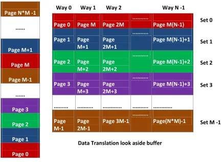
To describe our heap allocator, we start with a basic design and then incrementally add complex-ities and design details. Consider an N-way set associative DTLB supporting N ×M entries and a virtual address space with N ×M pages as shown in Figure 3.1. The DTLB handles translations for virtual pages of size page size.
Page N*M -1
... Page M+1 Page M Page M-1 ... Page 3 Page 2 Page 1 Page 0
Page 0 Page M Page 2M ...
Page M(N-1)
Page 1 Page M+1
Page 2M+1
...
Page M(N-1)+1
Page 2 Page M+2
Page 2M+2
...
Page M(N-1)+2
Page 3 Page M+3 Page 2M+3 ... Page M(N-1)+3 ... ... ... ... ... Page M-1 Page 2M-1 Page 3M-1 ... Page(N*M)-1 Set 0 Set 1 Set 2 Set 3 Data Translation look aside buffer
Set M
Way 0 Way 1 Way 2 Way N -1
Set 0
Set 1
Set 2
Set 3
Set M -1
Virtual address space
Figure 3.1: TLB coloring - max contiguous allocation = page size
We color pages 0, M, 2M+ 1 ...M(N−1) with the same color (red in this example) because all of them map to the same DTLB set. Similarly, pages 1,M+ 1, 2M+ 1 ...M(N−1) + 1 are colored blue and so on. We can see that no two virtual pages with different color can map to the same DTLB set. Each DTLB entry holds a translation for a virtual page of size page size. Since each DTLB set is given one color, the maximum contiguous virtual address space one can allocate of a particular color is given by thepage size.
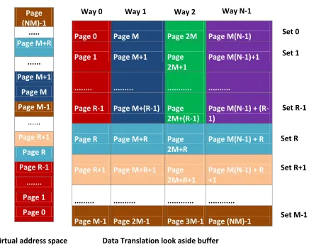
Let us now consider that a task needs to allocate more than page size bytes of contiguous memory in the virtual address space. This typically results in allocating arrays that span across multiple pages. In our basic design, such an allocation would span across two pages of different color assuming that the allocation is aligned to a page boundary. In order for the tasks to be able to allocate contiguous virtual memory of size greater than page size of a particular color, we reserve a certain number of DTLB sets for contiguous memory allocation. Consider the same example as in Figure 3.1 but with R sets reserved for contiguous memory allocation. Figure 3.2 shows an example of DTLB coloring that supports greater thanpage size allocations for a particular color. Page (NM)-1 ... Page M+R ... Page M+1 Page M Page M-1 ... Page R+1 Page R Page R-1 ... Page 1 Page 0
Page 0 Page M Page 2M Page M(N-1)
Page 1 Page M+1 Page 2M+1
Page M(N-1)+1
... ... ... ...
Page R-1 Page M+(R-1) Page 2M+(R-1)
Page M(N-1) + (R-1)
Page R Page M+R Page 2M+R
Page M(N-1) + R
Page R+1 Page M+R+1 Page 2M+R+1
Page M(N-1) + R +1
... ... ... ...
Page M-1 Page 2M-1 Page 3M-1 Page (NM)-1
Virtual address space Data Translation look aside buffer
Set 0 Set 1 Set R-1 Set M-1 Set R Set R+1
Way 0 Way 1 Way 2 Way N-1
Figure 3.2: TLB coloring - max contiguous allocation = page size×R
Since we have R sets reserved for contiguous allocations, the maximum amount of contiguous memory than can be allocated of a particular color is R×page size. Pages 0 to R−1 are colored red. Starting from page R until pageM−1, the coloring is performed in a similar way as described for the basic design. But pages M toM+ (R−1) are colored blue, again to support contiguous memory allocation. All the other virtual pages are colored in a similar manner.
2 MB to 1 GB depending on the configuration and the system in place. Computer architectures have a different DTLB structure to support huge page translations. Our heap allocator handles huge page allocation in a similar manner as described above.
We now generalize the methods for DTLB coloring described so far. Let M be the total number of DTLB sets, R be the number of sets reserved for contiguous allocations and N be the associativity of the DTLB. Let page size denote either the normal page size or huge page size of the system.
Corollary 1. Number of colors for allocations greater than page size is equal to N
Proof. Follows from the definition of N.
Letmax alloc sizerefer to the maximum contiguous allocation size that can be served by our
allocator. Let num colors upto page size refer to the number of colors available for allocations not exceedingpage size. Then,
max alloc size = page size×R, (3.1)
num colors upto page size =M−R. (3.2)
Chapter 4
Implementation
In this section, we describe the notation and the data structures to implement our heap allocator. We then present generic algorithms, which can be implemented on any architecture. Finally we present a specific instance of the generic algorithm that we have implemented on Intel Xeon E-2650.
4.0.1 Notations
We refer to the routine that initializes our heap allocator astlb malloc init, the heap allocator as
tlb mallocand the deallocator astlb free. These three routines are exposed as library functions to
user space applications. Compared to the standard heap allocation API,tlb malloc and tlb free
take an additional parameter, color. This parameter indicates the color of the memory region to be allocated. For each DTLB to be colored,tlb malloc init sets aside a virtual address space
of page size×dtlb sets bytes. Additional memory may be needed to handle page boundary
alignment. Our heap allocator serves allocations from this virtual address space pool that is set aside.
In this paragraph, we give a generic description of the internals of tlb malloc and tlb free. It is applicable to all the DTLBs to be colored. Depending on the number of bytes requested,
tlb malloc will call one of the functions as shown in Figure 4.1. LEN BYTES refers to the
number of bytes the allocator uses to store the size of the allocation. Similarly,tlb free will call one the functions shown in Figure 4.2 depending on the size of the allocation referenced byptr.
Figure 4.2: tlb free internals
4.0.2 Data structures
In this section, we introduce the data structures for our heap allocator. The description of the data structures is as generic as possible and is not tied to any specific language or implemen-tation. The following code snippet shows the structure to represent a chunk of free memory, which we refer to as thefree block.
struct mblock {
unsigned int length;
struct mblock * next; };
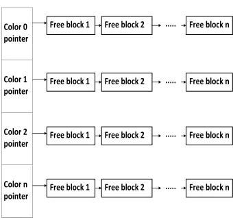
In addition to themblockstructure, we need afree listper color to keep track of the available free memory. Figure 4.3 shows a generic representation of thefree list.Color 0 pointer, Color 1
pointer, ... Color n pointer are the base pointers, which point to the first availablefree block of
that particular color. Eachfree block in turn points to the next availablefree block of the same
color. We need two such free lists, one forsmall allocations and the other forlarge allocations,
for each DTLB to be colored.
4.0.3 Generic algorithms
Algorithm 1 shows the pseudo code for our heap allocator. Each of the functions shown in Figure 4.1 invokes this algorithm. The parametertype is used to identify which specific function is invoked. Line 3 setsfree listto the appropriate list depending ontype andcolor. The function on line 5 is responsible for walking through the free list to find a suitable memory block and returns the starting address of the memory block. It is also responsible for storing the allocation size inLEN BYTES preceding the returned starting address.
Color 0 pointer
Color 1 pointer
Color 2 pointer
Color n pointer
Free block 1 Free block 2 ... Free block n ...
Free block 1 Free block 2 ... Free block n ...
Free block 1 Free block 2 ... Free block n ...
Free block 1 Free block 2 ... Free block n ...
Figure 4.3: Data structures
Algorithm 3 shows how to ascertain the bits in the virtual address that determine the DTLB set. The algorithm relies on the performance monitoring library PAPI [6]. Let no of entries
-in dtlb be the number of entries supported by the DTLB, dtlb assoc be the associativity of the
DTLB and page size denote the page size on the system. The algorithm takes an arraypage
-numbers as a parameter. Each element of the array indicates the page number to be accessed.
memory fence instruction to ensure that the memory references are issued in order and are recorded by the performance monitoring registers.
Algorithm 1 Heap allocator
1: function allocate memory(type,size,color)
2: mem ptr = NULL
3: free list = get free list(type,color)
4: if size != 0 & & free list != NULLthen
5: mem ptr = get free block(free list,size)
6: end if
7: return mem ptr
8: end function
Algorithm 2 Heap deallocator
1: function free memory(type,ptr,color)
2: length = get allocation length(ptr)
3: base ptr = get base ptr(ptr);
4: free list = get free list(type,color)
5: add block to free list(length,free list,base ptr)
6: end function
4.0.4 Intel Xeon E-2650
Algorithm 3 Find address bits which determine DTLB set
1: function find bits(page numbers[dtlb assoc])
2: n = 1000;
3: no of entries in dtlb = no of dtlb sets×dtlb assoc
4: int elements=page size/sizeof(int);
5: int *data = malloc((no of entries in dtlb+ 1)×page size);
6: conflict page = (no of entries in dtlb)×int elements;
7: PAPI read();
8: for i= 0 to ndo
9: forj= 0 to dtlb assoc do
10: data[ (pages[j])×int elements] = 2;
11: asm(”memory fence instruction;”);
12: end for
13: data[ (conf lict page)×int elements] = 2;
14: asm(”memory fence instruction;”);
15: end for
16: PAPI read();
Chapter 5
Experimental framework
In this section, we describe the experimental framework used to evaluate our new heap allocator. Algorithm 4 shows the pseudo code for our experimental setup. It implements periodic releases of a task set without any special support from the operating system or the hardware.start time
is a per task variable. It represents the time instant at which a task is first released. Function
t1 code represents the main body of a task. We use this experimental setup to evaluate both
synthetic and standard benchmarks.
Algorithm 4 Pseudo code for our experimental setup
1: struct timeval start time t1
2: function main
3: gettimeofday(&start time t1)
4: plustime(&start time t1,1) . add one second
5: pthread create(&t1, t1 code....)
6: ...
7: ...
8: end function
9: function t1 code
10: struct timeval wait, now, release
11: release = start time t1
12: t1 init()
13: loop
14: gettimeofday(&now)
15: minustime(&wait,&release,&now) .wait = release - now
16: nanosleep(&wait,&wait)
17: t1 job()
18: plus time(&release,&period)
19: end loop
We conducted experiments on an Intel Xeon E5-2650 processor running Linux 2.6.32. The system has 16 cores, each of which can run at 2 Ghz. The level one DTLB is 4-way set associative suporting 64 entries. The level two TLB supports 512 entries and is 4-way set associative. The level two TLB is shared between instruction and data. Both these TLBs handle 4kB sized page translations. For all experiments, we use rate monotonic scheduling of a set of tasks. On Linux, this can be achieved by setting the task priority while creating them. We use theSCHED FIFO
Chapter 6
Results
In this section, we first assess the predictability ofmalloc and tlb malloc. Then, we present our approach to identifying the DTLB sets which are subject to OS noise. Further, we estimate the L1 DTLB miss penalty and L2 DTLB miss penalty. We then evaluate the performance of our allocator with a set of synthetic benchmarks and standard benchmarks.
6.0.5 Predictability
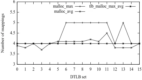
In this experiment, we create two tasks, T1 and T2. Each task allocates 32 pages. From the pool of 64 pages, the number of mappings to each DTLB set is recorded. We then compute the maximum and average mappings per DTLB set over 5 runs. Figure 6.1 shows the graph of the DTLB set versus the number of mappings. malloc max represents the maximum number of mappings that was observed when both tasks used malloc to allocate their pages. Similarly,
malloc avg represents the average number of mappings.tlb malloc max avg represents both the
maximum and average number of mappings when both tasks used tlb malloc to allocate their pages. Since the values are identical, we just use one line to represent both the cases.
The level one DTLB is 4-way set associative and supports 64 entries. The best possible DTLB set utilization would be the one in which each DTLB set has four mappings. In Figure
6.1, malloc max shows that DTLB sets 0-5, 12, 14 and 15 have four mappings. While DTLB
sets 6-11 and 13 have five mappings. malloc avg shows that the average mappings per DTLB set varies from 3.7 to 4.5. On the other hand, tlb malloc max avg shows each DTLB set to have exactly four mappings. From Figure 6.1, we can conclude that tlb malloc gives us more predictability compared tomalloc. Our allocator is predictable in the sense that it guarantees the DTLB set that will hold a particular page translation. Thus, if tasks T1 and T2 usemalloc
to allocate pages, they might interfere with each other in the DTLB. If, in contrast, T1 and T2
3 3.5 4 4.5 5 5.5 6
0 1 2 3 4 5 6 7 8 9 10 11 12 13 14 15
Number of mappings
DTLB set malloc_max
malloc_avg
tlb_malloc_max_avg
Figure 6.1: DTLB set utilization
6.0.6 Identifying noisy DTLB sets
So far, we have assumed that the entire DTLB is available for a set of tasks. But when the tasks run, they might invoke certain library functions. These library calls and OS activities, such as scheduling, interrupts, multi-level page tables etc., make use of the DTLB. We call this ”OS noise”. Hence, only certain number of ways of a DTLB set can be used by the tasks. The following describes our methodology to identify the number of ways that can be used by tasks beyond those already occupied due to OS noise.
tlb malloc gives us control over the DTLB set that will hold a particular page translation.
6.0.7 L1/L2 DTLB miss penalty
In this experiment, we determine the DTLB miss penalty for the Intel Xeon E-2650. We measure the execution cycles using the time stamp counter register. To calculate the L1 DTLB miss penalty, we map five pages to the same DTLB set using our allocator. We perform a warm up by accessing the pages once. We then access these five pages in a cyclic manner similar to the one shown in Lines 8-14 of Algorithm 3. This results in a L1 DTLB miss on every access. The average latency is computed by dividing the execution cycles by the number of L1 DTLB misses. This latency also factors in the cycles required for memory fence instructions and the overhead of the memory reference itself. To factor out this overhead via dual loop timing [1], we run another loop in which we access elements of an array in the similar manner as we access the five pages. Subtracting this overhead from the average latency calculated closely approximates the L1 DTLB miss penalty. Averaging over 10 runs, we determined the L1 DTLB miss penalty to be about 7.5 cycles. The standard deviation of the results was about 0.04.
To determine the L2 DTLB miss penalty, we use the same idea as mentioned above but map pages to different DTLB sets. We measure the latency of the warm up loop and compute the L2 DTLB miss penalty in a similar manner described above. By averaging over 10 runs, we found the L2 DTLB miss penalty to be about 1731 cycles with a standard deviation of 231.
6.0.8 Synthetic benchmarks
In the synthetic benchmarks, each task allocates and accesses a certain number of pages. During initialization (line 12 of algorithm 4), each task accesses its set of pages for the first time. We refer to this as thewarm up phase. When a job of either task is released, the job accesses its set of pages repeatedly. We refer to this as the repeated access phase. The Intel Xeon has a 4-way set associative level one DTLB. The worst case scenario occurs when the combined accesses of both tasks are greater than 4 pages and these pages map to the same DTLB set. The best case scenario occurs when the pages of each task map to different DTLB sets. We discuss two variants for this experiment:
Same set vs. different set-using tlb malloc
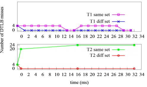
We use the following task set, where each task is denoted as (phase, period, execution): T1 (1ms, 2ms, 0.392ms), T2 (0ms, 16ms, 7.88ms). This task set ensures that the lower priority task suffers more than one preemption. In this experiment, we compare the number of DTLB misses that each task incurs in the best and the worst case scenario. For the worst case, both the tasks request four pages each fromtlb mallocsuch that all pages are of the same color. This scenario is termed assame set. Conversely, for the best case, T1 allocates four pages ofcolor 1
Figure 6.2 depicts the results for this experiment over two hyperperiods. The x axis rep-resents the time in milliseconds and the y axis reprep-resents the number of DTLB misses. The graphs for T1 and T2 are shown in the top half and bottom half of the figure, respectively. Each data point represents a job. The x axis shows the time at which the job is released and the y axis shows the number of DTLB misses for that job. The time instant before 0ms represents
the warm up phase. The corresponding value on y axis gives the number of DTLB misses for
thewarm up phase. We refer to this as the 0th job of a task.
Figure 6.2: Same set vs. diff set using tlb malloc
The misses for the worst case scenario are depicted as T1 same set and T2 same set. Jobs 1-5 (released at times 1ms, 3ms, 5ms, 7ms, 9ms) of T1 incur four misses because all these jobs preempt T2 and will need to reload its pages into DTLB. Job 6 of T1 incurs four misses because this job is released after T2, completes its execution and will also need to reload its pages into the DTLB. Jobs 7 and 8 of T1 have zero misses because when these jobs are released, T2 has finished its execution and, hence, these jobs do not have any interference. This behaviour repeats for each hyperperiod.
Every job of T2 is preempted five times. Hence, each job will incur 20 misses. The job in hyperperiod 1 has 20 misses while the jobs in other hyperperiods have 24 misses. This is because the job in hyperperiod 1 begins execution right away after the warm up. Jobs in other hyperperiods will need to load the pages into the DTLB first because the last job of T1 in the previous hyperperiod would have replaced T2’s mappings in DTLB.
from each other and will not be subject to inter task interference.
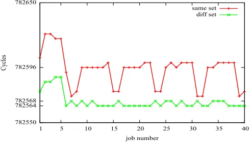
Figure 6.3 depicts the number of cycles needed by each job of T1 over five hyperperiods.
same set represents the experiment when both tasks share a DTLB set.diff set represents the
experiment when the two tasks do not share DTLB sets. For both runs, the jobs in hyperperiod one seem to require a larger number of cycles to execute as compared to the jobs in other hyperperiods. We attribute this to the warm ups happening in the architecture like the instruc-tion caches, data caches, branch predicinstruc-tion etc. The execuinstruc-tion cycles for jobs in the second hyperperiod for thesame set experiment varies depending upon the interference from T2. Jobs 9,10,11,12,13 preempt T2. Since these jobs of T1 have to reload their pages, they will incur an extra cost in terms of L1 DTLB miss penalty. Job 14 executes just after T2 completes its execution and will also need to reload its pages and, hence, incurs additional execution cycles. Jobs 15 and 16 are not subject to any interference from T2 and, hence, require lower cycles to complete their execution. diff set shows the execution cycles for jobs of T1 in the second hyperperiod to be consistent at about 782566 cycles. On average, the difference between the ex-ecution cycles of jobs 9,10,11,12,13 insame set anddiff set is about 30 cycles, which is roughly the L1 DTLB miss penalty for 4 pages. This behaviour is repeated for subsequent hyperperiods. From Figure 6.3, we further confirm that the tasks can be isolated from each other if they use different DTLB sets.
The execution cycles for jobs of T2 also include the cost of preemption along with cycles needed by the OS scheduler. Since we do not use a real time OS, the scheduling activities are not bounded and may take a variable amount of time. Since the measurements of execution cycles for jobs of T2 are subject to noise, it is difficult to attribute the variation in the execution cycles directly to the DTLB interference. Hence, we do not discuss the execution cycles for T2.
782550 782564 782568 782596 782650
1 5 10 15 20 25 30 35 40
Cycles
job number
same set diff set
malloc vs. tlb malloc
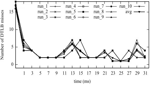
We use the following task set : T1 (1ms, 2ms, 0.385ms), T2 (0ms, 16ms, 7.38ms). In this experiment, each task initially allocates 32 pages. Each task then randomly chooses 14 pages from the pool of 32 pages. The tasks then perform a write operation on these 14 pages. Each task has thewarm up phase andrepeated access phase as described previously. For both tasks, we compare the number of DTLB misses when the tasks usemallocversustlb mallocto allocate its pages. For Figures 6.4-6.7, the axes and data points have the same meaning as described for Figure 6.2.
0 5 10 15
1 3 5 7 9 11 13 15 17 19 21 23 25 27 29 31
Number of DTLB misses
time (ms) run_1
run_2 run_3
run_4 run_5 run_6
run_7 run_8 run_9
run_10 avg
Figure 6.4: Malloc: Jobs vs DTLB misses for T1
0 5 10 15 20
1 3 5 7 9 11 13 15 17 19 21 23 25 27 29 31
Number of DTLB misses
time (ms)
runs 1-10 and average
Figure 6.4 shows the misses incurred by T1 when it usesmalloc. The graph shows the misses over 10 runs and also the average of them. The number of DTLB misses varies with each run depending upon the interference to T1. In hyperperiod one, on average, we observe that jobs 1 and 2 of T1 have about 5 misses, jobs 3-5 of T1 have about 2 misses, jobs 6 and 8 have about 3.5 misses and job 7 has about 6 misses. Similar values are observed for hyperperiod two. Figure 6.5 shows the misses incurred by T1 when it uses tlb malloc. The number of misses for all 10 runs are identical and, hence, we use a single line to represent all 10 runs and the average. In Figure 6.5, the observed misses are due to the warm up phase. Subsequent jobs of T1 do not incur any DTLB misses at all.
5 10 15 20 25
0 16
Number of DTLB misses
time (ms) run_1
run_2 run_3
run_4 run_5 run_6
run_7 run_8 run_9
run_10 avg
Figure 6.6: Malloc: Jobs vs DTLB misses for T2
0 5 10 15 20
0 16
Number of DTLB misses
time (ms)
runs 1-10 and average
Figures 6.6 and 6.7 show the results for T2 when it usesmalloc andtlb malloc, respectively. The results are similar to T1. In Figure 6.6, the number of misses formallocvary with each run. The average number of misses is about 15. In Figure 6.7, we again use a single line to represent the misses for all 10 runs and the average for tlb malloc, since the values are identical. The number of misses observed are due to the warm up phase while subsequent jobs do not incur any misses. From Figures 6.4-6.7, we can conclude that tlb malloc does provide task isolation with respect to the DTLB. These figures also show that the DTLB misses are predictable when the tasks usetlb malloc.
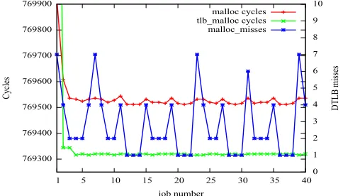
Figure 6.8 depicts the execution cycles for each job of T1 over five hyperperiods. We slightly modify the experiment described above. Instead of accessing the first four bytes of each page, we access bytes such that the memory accessed maps to different L1 data cache sets. By this modification, we ensure that we do not have conflicts in the L1 data cache.
769300 769400 769500 769600 769700 769800 769900
1 5 10 15 20 25 30 35 40 0
1 2 3 4 5 6 7 8 9 10 Cycles DTLB misses job number malloc cycles tlb_malloc cycles malloc_misses
Figure 6.8: Jobs vs execution cycles for T1
in Section 6.0.8, we do not measure the execution cycles for T2.
6.0.9 Malardalen benchmarks
For the experiments described in this section, we use benchmarks from Malardalen suite to show task isolation. The experimental setup is similar to that described in Section 6.0.8. We modified the benchmarks so that they use heap allocated regions instead of statically allocated ones.
Table 6.1 shows the characteristics of tasks for various experiments. Phase, period and execution time are in milliseconds. Column 1 shows the number of tasks in an experiment. The tasks are depicted in decreasing order of priority. In an experiment of j tasks, each task allocatesl64j mpages. The number of pages accessed by each task is shown in column 6 of Table 6.1. The loop bounds of therepeated access phase is varied to select an appropriate execution time for a task. We use the bubble sort, insertion sort, nth largest and statistics benchmarks for our experiments. We believe that these benchmarks represent basic functionalities of a real time task. Furthermore, we are constrained to small benchmarks since we only control DTLB entries that are not subject to OS noise under Linux.
Table 6.1: Task characteristics
# tasks Task Phase Period Execution Pages
2 T1 1 2 0.4 16
T2 0 54 27 16
3
T1 3 2 0.4 4
T2 2 3 0.9 7
T3 0 15 3.2 2
4
T1 3 2 0.2 2
T2 2 3 0.6 2
T3 1 5 1.1 1
T4 0 15 3.2 2
The experiments are designed in a way to show that our technique is applicable to a wide variety of scenarios. For two tasks, the periods are harmonic and the execution times are a combination of long and short runs. The number of pages accessed by each task are equal. The lower priority task T2 has more than one preemption. For three tasks, the periods are non-harmonic and have simultaneous releases of tasks. The number of pages accessed by each task differs.
the 0th (warm up) job. The x-axis denotes the total number of tasks in an experiment and the y-axis represents the average number of DTLB misses. malloc avg and tlb malloc avg are the average results over 5 hyperperiods computed over 5 runs when the tasks use malloc and
tlb malloc, respectively, to allocate their pages. For all the following graphs, tlb malloc avg has
a value of zero. The graphs start at a negative value to make the value oftlb malloc avgvisible. The start of DTLB misses formalloc avg are indicated by the positive value on the y-axis.
0 2 4 6 8 10 12 14
2 3 4
Number of DTLB misses
Total number of tasks 0 2 4 6 8 10 12 14
2 3 4
Number of DTLB misses
Total number of tasks
malloc_avg tlb_malloc_avg
Figure 6.9: T1
0 20 40 60 80 100 120 140
2 3 4
Number of DTLB misses
Total number of tasks 0 20 40 60 80 100 120 140
2 3 4
Number of DTLB misses
Total number of tasks
malloc_avg tlb_malloc_avg
Figure 6.10: T2
In the experiment with 2 tasks (Figures 6.9-6.10), if the tasks use malloc, we observe the number of DTLB misses to be about 13 and 130 for T1 and T2, respectively. If the tasks use
tlb malloc, both T1 and T2 incur no misses at all. The standard deviation of measurements
0 5 10 15 20 3 4
Number of DTLB misses
Total number of tasks 0 5 10 15 20 3 4
Number of DTLB misses
Total number of tasks
malloc_avg tlb_malloc_avg
Figure 6.11: T3
0 2 4 6 8 10 12 14 4
Number of DTLB misses
Total number of tasks 0 2 4 6 8 10 12 14 4
Number of DTLB misses
Total number of tasks
malloc_avg tlb_malloc_avg
Figure 6.12: T4
deviation is zero for the two tasks when they use tlb malloc.
For the experiment with 3 tasks (Figures 6.9-6.11), we can see that if the tasks usemalloc, the number of DTLB misses for T1, T2 and T3 are about 6, 32 and 20, respectively. But if the tasks use tlb malloc, then all three tasks incur zero misses. The standard deviation of results for T1, T2 and T3 are about 1.1, 5.5 and 2.5, respectively, when the three tasks use malloc. When the three tasks use tlb malloc, the standard deviation is zero.
For the experiment with 4 tasks (Figures6.9-6.12), the trend is similar. If the tasks use
malloc, the number of misses incurred are around 1.7, 6.8, 2.5 and 6.7 on average for T1, T2,
T3 and T4, respectively. If the four tasks usetlb malloc, then each task incurs zero misses. The standard deviation of results for T1, T2, T3 and T4 are about 0.5, 0.8, 1 and 4.8, respectively, when the tasks usemalloc. The standard deviation is zero when the tasks usetlb malloc. When the number of tasks is increased beyond four, the task set could not be isolated from OS noise resulting in DTLB misses even for tlb malloc. This is because we use a stock Linux system instead of a real time kernel and lack control for page allocation for code, stack and global variables.
The adpcm and fft benchmarks represent larger and more realistic task work loads. We
create two tasks with the following characteristics: T1 (1 ms, 4 ms, 2 ms) and T2 (0 ms, 20 ms, 4.6 ms) representing thefft and the adpcm benchmarks, respectively. The sum of the number of pages accessed by both the tasks is twenty. Figure 6.13 shows the results of this experiment. The description of the graph is identical to the ones described above except that the x-axis represents tasks in this figure.
In Figure 6.13, T1 and T2 incur about 10 and 34 DTLB misses, respectively, when the tasks use malloc. If the tasks use tlb malloc, then each task incurs zero misses. The standard deviation of the results for T1 and T2 are about 3.1 and 1.8, respectively, when the tasks use
malloc. The standard deviation of the results is zero when the tasks usetlb malloc.
0 5 10 15 20 25 30 35 1 2
Number of DTLB misses
Task 0 5 10 15 20 25 30 35 1 2
Number of DTLB misses
Task
malloc_avg tlb_malloc_avg
Figure 6.13: T1 and T2 use fft and adpcm benchmarks, respectively
6.0.10 Mi benchmarks
In this section, we describe the experiments that we conducted using Mi benchmarks. We create two tasks, T1 (1 ms, 7 ms, 2.5 ms) and T2 (0 ms, 14 ms, 5.3 ms). T1 represents the
FIR benchmark from Malardalen suite, while T2 represents theadpcm benchmark. T1 and T2 operate on input data of 16 kB and 450 kB, respectively. The adpcm benchmark from the Mi suite operates on actual audio files and performs file IO, while theadpcm benchmark from the Malardalen suite described in the previous experiment operates on randomly generated data. Figure 6.14 depicts the results for this experiment. The description of the graphs is identical to that of Figure 6.13.
0 2 4 6 8 10 12 14 1 2
Number of DTLB misses
Task 0 2 4 6 8 10 12 14 1 2
Number of DTLB misses
Task
malloc_avg tlb_malloc_avg
Figure 6.14: Combination of Malardalen and Mi benchmarks
In Figure 6.14, T1 and T2 incur about 9 and 3 misses, respectively, when the tasks use
Chapter 7
Related Work
Providing a virtual address space for safety critical systems with different integrity levels has been explored by Bennett and Audsley [4]. The main goal of their work was to provision virtual memory for safety critical systems without complicating timing analysis for tasks with hard deadlines. To support the concept of a real time address space, kernel modifications are imperative. Their paper, however, neither considered tasks that use dynamic memory allocation nor the interference due to TLB sets shared by tasks. Our approach is different in the sense that no kernel modifications are needed and real time tasks can use dynamic memory allocation with bounded or even without TLB interference.
Puaut et al. [14] have proposed a compiler approach to make paging more predictable. The main idea of the paper is to identify page in and page out points of virtual pages at compile time. This method relies on the static knowledge of the possible references to virtual pages. However, the focus of their paper is to make demand paging more predictable while ours is on task isolation with respect to TLB.
Compiler-directed page coloring proposed by Bugnion et al. [5] involves three key phases. First, a compiler creates a summary of array references and communicates this information to the run time system. The run time system then uses machine-specific parameters like the cache size to generate a preferred color for the physical frame. The operating system then uses this color as a hint and does a best effort to honor them. This technique is applicable to physically indexed caches while our focus is on TLBs. In addition, our technique does not need profiling or modifications to the compiler and the operating system.
cache conflicts. Ward et al. [17] proposed cache locking and cache scheduling for the last level caches. Their scheme treats cache ways as resources that must be acquired by tasks before beginning their execution. These techniques alleviate interference with respect to physically indexed caches but do not consider the interference in the TLB.
Chapter 8
Future Work and Conclusion
We presented the concept of TLB coloring in which virtual pages are colored such that pages of different color do not map to the same TLB set. Using this concept, we designed and imple-mented a heap allocator, tb malloc, that guarantees the DTLB set that will hold a particular page translation.
We conducted experiments on the X86 64 architecture using a set of synthetic and standard benchmarks. Our finding is thattlb malloc provides task isolation for real time tasks. Further, the number of DTLB misses are predictable using our allocator. This predictability potentially enables static timing analysis tools to compute significantly tighter bounds on the WCET.
REFERENCES
[1] Neal Altman and Nelson Weiderman. Timing variation in dual loop benchmark. ACM
SIGAda Ada Letters, 8(3):98–106, 1988.
[2] AMD AMD. Bios and kernel developers guide (bkdg) for amd family 15h models 00h-0fh processors.
[3] ARM ARM. Arm a-9 technical reference manual.
[4] MD Bennett and Neil C Audsley. Predictable and efficient virtual addressing for safety-critical real-time systems. In Real-Time Systems, 13th Euromicro Conference on, 2001., pages 183–190. IEEE, 2001.
[5] Edouard Bugnion, Jennifer M Anderson, Todd C Mowry, Mendel Rosenblum, and Mon-ica S Lam. Compiler-directed page coloring for multiprocessors. ACM SIGPLAN Notices, 31(9):244–255, 1996.
[6] Jack Dongarra, Shirley Moore, Philip Mucci, Keith Seymour, and Haihang You. Accurate cache and tlb characterization using hardware counters. InComputational Science-ICCS 2004, pages 432–439. Springer, 2004.
[7] Christian Ferdinand and Reinhard Wilhelm. On predicting data cache behavior for real-time systems. In Languages, Compilers, and Tools for Embedded Systems, pages 16–30. Springer, 1998.
[8] J¨org Herter, Peter Backes, Florian Haupenthal, and Jan Reineke. Cama: A predictable cache-aware memory allocator. In Real-Time Systems (ECRTS), 2011 23rd Euromicro
Conference on, pages 23–32. IEEE, 2011.
[9] Intel Intel. and ia-64 architectures software developers manual. Volume 3A: System
[10] Jochen Liedtke, Hermann Hartig, and Michael Hohmuth. Os-controlled cache predictabil-ity for real-time systems. In Real-Time Technology and Applications Symposium, 1997.
Proceedings., Third IEEE, pages 213–224. IEEE, 1997.
[11] Renato Mancuso, Roman Dudko, Emiliano Betti, Marco Cesati, Marco Caccamo, and Rodolfo Pellizzoni. Real-time cache management framework for multi-core architectures.
InReal-Time and Embedded Technology and Applications Symposium (RTAS), 2013 IEEE
19th, pages 45–54. IEEE, 2013.
[12] Miguel Masmano, Ismael Ripoll, Alfons Crespo, and Jorge Real. Tlsf: A new dynamic memory allocator for real-time systems. InReal-Time Systems, 2004. ECRTS 2004.
Pro-ceedings. 16th Euromicro Conference on, pages 79–88. IEEE, 2004.
[13] Frank Mueller. Timing analysis for instruction caches. Real-Time Systems, 18(2-3):217– 247, 2000.
[14] Isabelle Puaut and Damien Hardy. Predictable paging in real-time systems: A compiler approach. InReal-Time Systems, 2007. ECRTS’07. 19th Euromicro Conference on, pages 169–178. IEEE, 2007.
[15] Harini Ramaprasad and Frank Mueller. Bounding worst-case data cache behavior by analytically deriving cache reference patterns. In Real Time and Embedded Technology
and Applications Symposium, 2005. RTAS 2005. 11th IEEE, pages 148–157. IEEE, 2005.
[16] Harini Ramaprasad and Frank Mueller. Bounding preemption delay within data cache reference patterns for real-time tasks. InReal-Time and Embedded Technology and
Appli-cations Symposium, 2006. Proceedings of the 12th IEEE, pages 71–80. IEEE, 2006.
[17] Bryan C Ward, Jonathan L Herman, Christopher J Kenna, and James H Anderson. Out-standing paper award: Making shared caches more predictable on multicore platforms. In
Real-Time Systems (ECRTS), 2013 25th Euromicro Conference on, pages 157–167. IEEE,
[18] Randall T White, Frank Mueller, Christopher A Healy, David B Whalley, and Marion G Harmon. Timing analysis for data caches and set-associative caches. InReal-Time
Technol-ogy and Applications Symposium, 1997. Proceedings., Third IEEE, pages 192–202. IEEE,
1997.
[19] Reinhard Wilhelm, Jakob Engblom, Andreas Ermedahl, Niklas Holsti, Stephan Thesing, David Whalley, Guillem Bernat, Christian Ferdinand, Reinhold Heckmann, Tulika Mitra, et al. The worst-case execution-time problemoverview of methods and survey of tools.
ACM Transactions on Embedded Computing Systems (TECS), 7(3):36, 2008.
[20] Heechul Yun, Renato Mancuso, Zheng-Pei Wu, and Rodolfo Pellizzoni. Palloc: Dram bank-aware memory allocator for performance isolation on multicore platforms. In Real-Time
.1
Introduction
In Appendix A, we first describe in detail the results of an experiment we conducted to compare
mallocandtlb malloc. Then, we describe in detail the experiments we conducted to demonstrate
Appendix A
Detailed Experimental Results
A.1
malloc vs. tlb malloc experiment
In this appendix, we describe an experiment in which we comparemalloc and tlb malloc. The experiment set up is similar to that described in Section 6.0.8. We use the following task set: T1 (1ms, 2ms, 0.39 ms), T2 (0ms, 16ms, 7.8 ms). Each task initially allocates 32 pages and then randomly chooses 16 pages from the pool of 32 pages.
Figure A.1 shows the misses incurred by T1 when it uses malloc. The graph shows the misses over 10 runs and also the average of them. The number of DTLB misses varies with each run depending upon the interference caused to T1. In hyperperiod one, on average, we observe that jobs 1-6 of T1 have about 7 misses while jobs 7 and 8 of T1 have about 5.5 and 3.4 misses, respectively. Similar values are observed for hyperperiod two. Figure A.2 shows the misses incurred by T1 when it usestlb malloc. The number of misses for all 10 runs is identical and, hence, we use a single line to represent all 10 runs and the average. In Figure A.2, the observed misses are due to thewarm up phase. Subsequent jobs of T1 do not incur any DTLB misses.
0 5 10 15 20
1 3 5 7 9 11 13 15 17 19 21 23 25 27 29 31
Number of DTLB misses
time (ms) run_1
run_2 run_3
run_4 run_5 run_6
run_7 run_8 run_9
run_10 avg
Figure A.1: Malloc: Jobs vs. DTLB misses for T1
0 4 10 20
1 3 5 7 9 11 13 15 17 19 21 23 25 27 29 31
Number of DTLB misses
time (ms)
runs 1-10 and average
Figure A.2: tlb malloc: Jobs vs DTLB misses for T1
0 4 10 20
0 16
Number of DTLB misses
time (ms)
runs 1-10 and average
0 15 30 45 60 75
0 16
Number of DTLB misses
time (ms) run_1 run_2 run_3 run_4 run_5 run_6 run_7 run_8 run_9 run_10 avg
Figure A.3: Malloc: Jobs vs. DTLB misses for T2
782500 782550 782600 782650 782700 782750 782800 782850 782900
1 5 10 15 20 25 30 35 40
Cycles
job number
same set run1 same set run2 same set run3 same set run4 same set run5 diff set run1 diff set run2 diff set run3 diff set run4 diff set run5
Figure A.5: Jobs vs. execution cycles for T1
A.2
Timing results
Figure A.5 shows the number of cycles needed for each job of T1 for the experiment described in Section 6.0.8. The x-axis denotes the job number and the y-axis denotes the number of execution cycles.
observe that they take higher execution cycles as compared to same set runs in the lower band. We believe that the formation of bands and the same set taking shorter execution cycles in some runs is due to the memory hierarchy. Our allocator provides isolation only with respect to the DTLB. There may be interference in the L1/L2 caches, DRAMs etc. which can cause the observed behavior.
The execution time for jobs of T2 also includes the cost of preemption along with cycles consumed by the OS scheduler. Since we do not use a real time OS, the scheduling activities are not tightly bounded and may take a variable amount of time. Since the measurements of execution cycles for jobs of T2 are subject to noise, it is difficult to attribute the variation in the execution cycles directly to the DTLB interference. Though the results are not conclusive, for the sake of completeness, we show the execution cycles of each job of T2 for the experiments discussed in this section.
Figure A.6 depicts the execution cycles for each job of T2 for the same set and diff set
experiment. We observe that the first job tends to take longer than subsequent ones, which can be attributed to caching at all levels (L1, L2, L3). Since T2’s response time exceeds 9.84ms and is interrupted by five preemptions of T1, OS scheduling and timer interrupts inflict coarse-grained noise that dominates any fine-grained TLB effects.
1.986e+007 1.987e+007 1.988e+007 1.989e+007 1.99e+007 1.991e+007 1.992e+007 1.993e+007
1 2 3 4 5
Cycles
job number
same set run1 same set run2 same set run3 same set run4 same set run5 diff set run1 diff set run2 diff set run3 diff set run4 diff set run5
Figure A.6: Jobs vs. execution cycles for T2
We set up an experiment to compare the execution cycles needed by task T1 when it uses
malloc and tlb malloc. The experiment is similar to the one described in Section 6.0.8. Figure
A.7 depicts the execution cycles of each job of T1. The description of the graph is the same as that of Figure A.5.
769300 769400 769500 769600 769700 769800 769900
1 5 10 15 20 25 30 35 40
Cycles job number malloc run1 malloc run2 malloc run3 malloc run4 malloc run5 tlb_malloc run1 tlb_malloc run2 tlb_malloc run3 tlb_malloc run4 tlb_malloc run5
Figure A.7: Jobs vs. execution cycles T1
tlb malloc. Ideally, only malloc runs should have variations in the execution cycles across jobs
since the jobs are subject to DTLB interference. But we observe a similar behaviour for tlb
-malloc as well. Figure A.8 depicts the execution cycles needed by each job of T2, which are
shown for completeness but remain inconclusive as OS noise dominates any TLB effects.
1.797e+007 1.798e+007 1.799e+007 1.8e+007 1.801e+007 1.802e+007
1 2 3 4 5
Cycles job number malloc run1 malloc run2 malloc run3 malloc run4 malloc run5 tlb_malloc run1 tlb_malloc run2 tlb_malloc run3 tlb_malloc run4 tlb_malloc run5
Figure A.8: Jobs vs. execution cycles for T2
results of this experiment. 769300 769400 769500 769600 769700 769800 769900
1 5 10 15 20 25 30 35 40
Cycles job number malloc run1 malloc run2 malloc run3 malloc run4 malloc run5 tlb_malloc run1 tlb_malloc run2 tlb_malloc run3 tlb_malloc run4 tlb_malloc run5
Figure A.9: Jobs vs. execution cycles for T1
From Figure A.9, observe that when the tasks use tlb malloc, the execution cycles of each job is almost constant. While if the tasks use malloc, the execution cycles for each job varies depending upon the DTLB interference caused. Figure A.10 depicts the execution cycles for each job of T2.
1.797e+007 1.798e+007 1.799e+007 1.8e+007 1.801e+007 1.802e+007 1.803e+007
1 2 3 4 5
Cycles job number malloc run1 malloc run2 malloc run3 malloc run4 malloc run5 tlb_malloc run1 tlb_malloc run2 tlb_malloc run3 tlb_malloc run4 tlb_malloc run5
Figure A.10: Jobs vs. execution cycles T2
represent the statistics and the bubble sort benchmarks, respectively. Figure A.11 depicts the execution cycles for each job of T1.
871650 871700 871750 871800 871850 871900 871950 872000
0 10 20 30 40 50 60 70 80 90
Cycles job number malloc run1 malloc run2 malloc run3 malloc run4 malloc run5 tlb_malloc run1 tlb_malloc run2 tlb_malloc run3 tlb_malloc run4 tlb_malloc run5
Figure A.11: Jobs vs. execution cycles for T1
In Figure A.11, we observe a similar behavior to that of Figure A.7. The execution cycles of jobs vary for bothmallocandtlb malloc. As we already pointed out in the preceding paragraphs, this large variation in execution cycles is due to L1 data cache conflicts. Since the Malardalen benchmarks are going to access all bytes in a page, we cannot avoid L1 data cache conflicts. Figure A.12 depicts the execution cycles for each job of T2, again shown for completeness only as noise dominates TLB effects.
4.924e+007 4.926e+007 4.928e+007 4.93e+007 4.932e+007 4.934e+007 4.936e+007 4.938e+007
1 2 3 4 5
Cycles job number malloc run1 malloc run2 malloc run3 malloc run4 malloc run5 tlb_malloc run1 tlb_malloc run2 tlb_malloc run3 tlb_malloc run4 tlb_malloc run5