Transactions of the 17th International Conference on Structural Mechanics in Reactor Technology (SMiRT 17) Prague, Czech Republic, August 17 –22, 2003
Paper # K08-1
SEISMIC QUALIFICATION OF SPENT FUEL STORAGE STACKS
Lester S. S. Lee and Wei Liu
Atomic Energy of Canada Limited, Mississauga, Ontario, Canada
ABSTRACT
CANDU reactors designed in Canada are built and operated worldwide for producing electricity economically. The operation of CANDU reactors yields spent fuel bundles that are removed from the reactor core by means of remote mechanisms. The spent fuel bundles are transferred to a Spent Fuel Bay (SFB) for underwater cooling and long term storage. Spent fuel bundles are loaded onto stainless steel trays. A number of such trays are stacked vertically and stored on the floor of the SFB. It is necessary that the storage stacks maintain their structural integrity and stability under a severe design earthquake. This paper presents the methods and process used for seismic qualification of the storage stacks by analysis.
The finite element models of the storage stack are developed to represent the behavior of the structure. The models are created for each individual tray and then restructured by using the sub-structuring technique. In this process, the stiffness matrix of a tray is condensed into a number of key points that include the points of contact between trays. In a storage stack the trays are pressed together by their own deadweight and by the weight of the fuel bundles and locked in place against each other at a number of contact points having no structural continuity. It can generally be assumed that the trays are in contact with each other. However the effectiveness of contact between the trays during seismic motion is uncertain due to erratic deflection, manufacturing irregularities and field conditions. Consequently a sensitivity study is carried out to assess the effect of lack of continuity at some of the contact points. The stack models are grouped into a number of multiple stack arrangements with the safeguard covers. They are grouped into different configurations and analyzed. Since the stacks are submerged in water, hydrodynamic effects are considered in the seismic model to more accurately predict the seismic behavior. A time-history analysis was then performed to determine seismic loads and stresses, to assess the integrity of the structure and to verify its overall stability against sliding and overturning.
KEY WORDS: spent fuel storage stack, structure, seismic qualification, stability, integrity.
INTRODUCTION
There are various types of structures used for under water storage of spent fuel in nuclear power plants. The most common ones are stacks, baskets and racks. Most spent fuel storage structures are of the free standing type. During an earthquake, complex movements between components of the spent fuel assemblies, the rack structure and the pool floor can occur such as sliding, uplifting and rocking. Many experimental tests and non-linear analyses for storage structures (racks) have been performed [1]. However finite element analysis with representative model is an acceptable method for seismic qualification of such structures. For CANDU pressurized heavy water reactors, stack and basket type structures are used for spent fuel storage. This paper deals with the seismic qualification of stack type structures used for the storage of spent fuel bundles extracted from CANDU 6 type reactors.
DESCRIPTION OF THE STRUCTURE
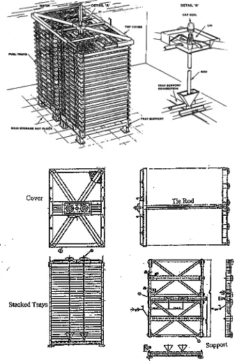
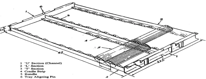
Each storage tray holds 24 fuel bundles in two rows, as shown in Fig. 2(a). The tray is made of welded stainless steel construction, and consists of two channel sections, interconnected by two angle sections at both ends and a Tee section in the middle. Contoured cradle strips provide support for the cylindrical fuel bundles. Each tray is provided with two tapered locating pins on the top channel and two slots on the bottom channel at matching locations. The pins engage with the slots of the next-higher tray in the stack. Figure 2(b) shows a finite element model of a storage tray.
The support tray located at the bottom is structurally similar to the storage tray. It consists of two channels at the ends, a diagonally cross-braced steel frame and a reinforcing pipe running through the middle. Each support tray is provided with 6 legs or pads that transfer loads to the floor. The channel sections at the ends are partially boxed-in with gussets to provide additional strength. Two tapered locating pins are provided at the top of the channels that lock in with the matching slots in the first storage tray in the stack. Figure 3 shows a finite element model of a support tray.
SEISMIC QUALIFICATION OF THE STRUCTURE
The seismic qualification of the structure is achieved by performing a seismic analysis of the mathematical models of the spent fuel stacks for a Design Basis Earthquake (DBE). For typical CANDU sites the DBE has a ground acceleration of 0.2 g. The time history method of analysis was adopted. The time history motion at the floor of the SFB was generated and used as input for the analysis. The time-history modal superposition method was used to perform seismic response using the STARDYNE computer program. A number of different models have been developed and analyzed to represent the arrangement of a single storage stack and of stacks in groups of 2x1, 2x2, 2x3 and 3x2. The finite element sub-structuring technique was used. The analysis showed that the stresses in the structural components of the storage stacks are below the code allowable limits thus ensuring structural integrity. It is also necessary to verify the stability against toppling and sliding that may damage the fuel bundles. Seismic qualification is required for various configurations as the number of trays per stack can vary, and stacks can be grouped in different arrangements. Analysis cases with and without safeguard covers were also included to account for the possibility of occurrence of an earthquake before or after covers are installed. A number of seismic models are therefore required to represent different geometry and configurations of stacks during the fuel storage sequence.
SEISMIC MODELS AND BOUNDARY CONDITIONS
Modeling Methodology
The finite element method is adopted to represent structural behaviors. As the full finite element model of a stack can be too large and have an excessive number of degrees of freedom, the sub-structuring technique was used in order to reduce the degrees of freedom to a manageable number. The modeling process consists of the following five steps:
(a) Finite element models for structural components such as trays, supports and covers are created. The models of the storage tray and the support tray are shown in Figures 2b and 3 respectively.
(b) Each finite element model is then condensed by the sub-structuring technique to a reduced stiffness matrix at a number of required boundary nodes. The boundary nodes consist of nodes for attached masses and for contact with neighboring components.
(c) The model of a single stack with multiple trays is formed by combining the stiffness matrices of the structural components (storage trays, support tray, covers etc.) with appropriate geometry and contact conditions between components. The contact condition between trays is represented by springs or beams having large stiffness values. A second condensation is then performed on the model of a single stack. After the second condensation, the interior nodes and springs or beams representing the contacts between trays are removed from the active degrees of freedom. The mass nodes for each tray, the bottom boundary nodes of the first tray and the top boundary nodes of the top tray of each stack are retained as active degrees of freedom.
(d) The global models of groups of stacks are then produced by creating the geometry and combining the stiffness matrices of the individual stacks.
(e) The masses are assigned in the global model. The masses consist of the mass of steel structural members and the fuel bundles. Additionally the hydrodynamic effect in the form of impulsive mass of water induced by vibration of submerged structure is considered. Masses are determined by manual calculation using the principal of tributary area and assigned at a number of selected nodes.
It is noted that the global model developed by the finite element method with the sub-structuring condensation technique retains the original stiffness properties of the structure. This is preferable over creating a full model of the stack, as the full model will be too huge and will need large computer storage space and running time.
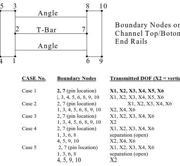
During the first condensation, boundary nodes in each component are created. During the second condensation in creating the model of stacks, successive trays or components are assumed to transfer loads at a number of contact nodes. Ten contact nodes are defined on the basis of the geometric configuration of the structure. These nodes are located at the top and bottom of the channel section as shown in Figure 4. Points 4,5,9 and 10 are the outer most corners of the channel section. Points 1,3,6 and 8 are at the inside face of the channel. Points 2 and 7 represents the location of the slot or pin provided for positioning of trays. The exact contact condition is not known and can vary from tray to tray, stack to stack, and can not be fully predicted due to manufacturing tolerance and misalignment. For that reason, sensitivity study is carried out to assess the effects of different contact conditions on the seismic response of the stacks. Boundary Condition
The global models of the stacks are supported on six legs or pads for each stack on the concrete floor. The boundary conditions at the bottom of the supporting legs or pads are assigned to be either fixed or hinged. The results from different conditions are enveloped for simplification and conservatism. It is assumed that the legs or pads do not uplift in the vertical direction. This assumption is verified by assessing the possibility of overturning of the structure. It is also assumed that stacks are restrained in the horizontal direction. This is achieved by considering either the friction between the legs or pads and floor or by using steel stoppers attached to the steel-liner that are anchored to the concrete floor.
SENSITIVITY ANALYSIS FOR CONTACT CONDITIONS BETWEEN TRAYS
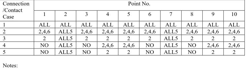
The contact conditions between trays are not exactly known. They can vary from a full contact with transfer of load components of six degrees of freedom to a no contact with free movements and no load transfer. Partial contacts conditions with load transfer of some of the load components is possible. A set of contact conditions are defined by varying the transmitted degree-of-freedom with an understanding of the physical behavior of the structure. Accordingly, five cases with different conditions as given in Table 1 have been included in a sensitivity study to assess the effects of these contact conditions on the seismic responses of the stacks.
Case 1
In Case 1, loads at all 10 points of neighboring components are fully in contact which means that load transfer in all six directions (X1, X2, X3, X4, X5 and X6) are possible.
Case 2
In Case 2, loads are transferred at points 2 and 7 at pin locations in all directions except X5 which is the rotation about the vertical axis. At all other points, loads are only transferred in the X2, X4, and X6 directions, while in the horizontal X1, X3 and X5 directions, contact conditions are free.
Case 3
In Case 3, loads are transferred at points 2 and 7 at pin locations in all directions except X5 which is the rotation about the vertical axis. At all other points, loads are transferred in X2 direction which is vertical.
Case 4
In Case 4 loads are transferred at points 2 and 7 at pin locations in all directions except X5 which is the rotation about the vertical axis. At points 4,5,9 and 10 loads are transferred in the X2, X4, and X6 directions only. At points 1,3,6 and 8 loads are not transferred in any direction, in other words, contact conditions are free.
Case 5
In Case 5 loads are transferred at points 2 and 7 at pin locations in all directions except X5 which is the rotation about the vertical axis. At points 4,5,9 and 10, loads are transferred in the X2 direction only. At points 1,3,6 and 8 loads are not transferred in any direction, i.e. the contact does not exist.
Seismic analyses are performed for these five cases and the seismic responses of the structure are determined. The acceleration responses at the top tray are given in Table 2 for the above five cases of contact condition. The reaction forces at the bottom of the stack consisting of shear forces and moments are given in Table 3 for the above five cases. It is seen that the maximum acceleration response and the reaction forces are not sensitive to the assumed contact conditions. This confirms that any one of the contact conditions can be considered adequate in the analysis of the structure for seismic qualification.
STRUCTURAL INTEGRITY AND STABILITY CHECKING
were utilized. These stresses are compared with the code allowable values. Structural integrity is ensured as long as the actual stresses are lower than the allowable values.
It is also required that the stacks in any possible configuration maintain the stability against sliding and overturning. Stability checking has been performed using the results of the seismic analysis. For that purpose the sliding forces and the overturning moments are used. The following two factors are considered in establishing the stability of the structure.
a) Uplifting Factor
The Uplifting Factor is defined as the ratio of the overturning moment and the restoring moment. In calculating the overturning moment, the inertial effects and the hydrodynamic effects due to the submergence condition are considered. The stabilizing moment is produced by the weight of the structure reduced by the buoyancy forces. The structure is considered stable if the Uplifting Factor is lower than 1.0. If the Uplifting Factor is greater than 1.0 the structure can uplift or separation can occur between the support legs or pads and the concrete floor or between the trays.
(b) Sliding Factor
The Sliding Factor is defined as the ratio of the seismic shear force to the vertical force at the base. The vertical force is obtained by the weight of the structure reduced by the buoyancy force and the vertical seismic inertial force. The structure is considered stable as long as the Sliding Factor is lower than the friction coefficient between the support legs or pads and the floor. If the Sliding Factor exceeds the friction coefficient, additional restraints or stoppers are necessary to restrain the structure.
It is noted that the above stability criteria are conservative to determine the seismic stability of a structure. Even if the above criteria are not met and some uplifting, rocking and/or sliding occur, the stacks may still be stable during and after an earthquake since the earthquake motion is transient in nature, i.e. the uplifting, rocking and/or sliding motion may be mitigated and/or reversed as the earthquake transient motion chages its amplitude or reverses its motion direction.
CONCLUSIONS
The spent fuel storage stacks used for CANDU reactors must be seismically qualified to the Design Basis Earthquake. To that purpose, the structural integrity and stability of the stacks were examined. Various possible configurations of the storage stacks were modeled by varying the number of trays per stack and assuming different grouping arrangements of the stacks. The finite element models were developed to represent the behavior of the structure. Two levels of stiffness condensation by applying the sub-structuring technique to the model were used to simplify and reduce the model size without affecting the original stiffness characteristic.
Hydrodynamic effects were considered in generating the seismic model. The contact conditions between consecutive trays were defined at selected boundary nodes. A sensitivity study was carried out to assess the effects of various schemes of contact conditions on the global response. It is concluded that the global responses of the stacks are not sensitive to the assumed contact conditions.
REFERENCES
Table 1 Load Transfer Conditions at Contact Nodes
Point No. Connection
/Contact
Case 1 2 3 4 5 6 7 8 9 10
1 ALL ALL ALL ALL ALL ALL ALL ALL ALL ALL
2 2,4,6 ALL5 2,4,6 2,4,6 2,4,6 2,4,6 ALL5 2,4,6 2,4,6 2,4,6
3 2 ALL5 2 2 2 2 ALL5 2 2 2
4 NO ALL5 NO 2,4,6 2,4,6 NO ALL5 NO 2,4,6 2,4,6
5 NO ALL5 NO 2 2 NO ALL5 NO 2 2
Notes:
ALL Complete load transfer in 3 transnational and 3 rotational directions ALL5 Load transfer in all direction except X5
NO No load transfer (i.e. separated)
2 Load transfer in the vertical X2 direction only
2,4,6 Load transfer in the vertical X2 direction and in X4 and X6 directions
Table 2 Maximum Acceleration Response at Top Tray
Connection/Contact Case
AX1 (g) AX2 (g) AX3 (g)
1 0.414 0.163 0.419 2 0.414 0.165 0.425 3 0.414 0.163 0.425 4 0.414 0.164 0.425 5 0.415 0.149 0.426
Table 3 Maximum Reaction Forces at Base
Connection/Contact Case
FX1 (lb)
FX2 (lb)
FX3 (lb)
MX1 (in-lb)
MX2 (in-lb)
MX3 (in-lb)
1 7,336 2,212 9,549 606,703 323,108 570,573
2 7,277 2,258 8,825 579,212 317,562 569,161
3 7,231 2,280 8,819 580,088 314,767 565,814
4 7,244 2,271 8,822 579,760 315,629 566,807
(a) Sketch of a Spent Fuel Storage Tray
(b) Finite Element Model for Spent Fuel Storage Tray
Figure 3: Finite Element Model for S/F Storage Tray Support
5
3
2
4
1
8
10
6
9
7
A ngle
T -B ar
A ngle
B oundary N odes on
C hannel T op/B otom
E nd R ails
CASE No. Boundary Nodes Transmitted DOF (X2 = vertical)
Case 1 2, 7 (pin location) X1, X2, X3, X4, X5, X6
|, 3, 4, 5, 6, 8, 9, 10 X1, X2, X3, X4, X5, X6
Case 2 2, 7 (pin location) X1, X2, X3, X4, X6
1, 3, 4, 5, 6, 8, 9, 10 X2, X4, X6
Case 3 2, 7 (pin location) X1, X2, X3, X4, X6
1, 3, 4, 5, 6, 8, 9, 10 X2
Case 4 2, 7 (pin location) X1, X2, X3, X4, X6
1, 3, 6, 8 separation (open)
4, 5, 9, 10 X2, X4, X6
Case 5 2, 7 (pin location) X1, X2, X3, X4, X6
1, 3, 6, 8 separation (open)