Design and Analysis of Leaf Spring Bracket in
Air Suspension Vehicle Using FEA
R.Prakash
1V.Kavinraj
2, A.Anandajayakumar
3S.Karthik4
Faculty, Department of Mechanical Engineering, Karpagam College of Engineering, Coimbatore, TN, India1,2,3&4.
ABSTRACT: This paper presents the technique of the fatigue analysis of spot-weld joints to predict the lifetime and
location of the weakest spot-welds due to the imposed loading conditions. A simple model was used to illustrate the technique of spot-weld fatigue analysis. Finite element model and analysis were carried out utilizing the finite element analysis commercial codes. Linear elastic finite element analysis was carried out to predict the stress state along the weld direction. It can be seen from the results that the predicted life greatly influence the sheet thickness, spot diameter and loading conditions of the model. Acquired results were shown the predicted life for the nugget and the two sheets around the circumference of the spot-weld at which angle the worst damage occurs.
KEYWORDS: spot-weld joints, Linear elastic, damage occurs
I. INTRODUCTION
The suspension system supports the weight of the vehicle and provides for a smoother ride for the driver and passengers. But suspension systems also protect your vehicle from damage and play a critical role in maintaining safe driving conditions. A well functioning suspension system shields a vehicle from excessive wear and potential structural damage associated with prolonged exposure to bumps and pot holes but also keeps the wheels pressed firmly to the ground for traction. Sprung mass (weight) refers to vehicle parts supported on the suspension system, such as the body, frame, and engine. The sprung weight typically includes the body, frame, the internal components, passengers, and cargo. By contrast, unspring weight refers to the components that follow the road contours, such as wheels, tires, brake assemblies, and any part of the steering and suspension not supported by the springs. The suspension system isolates the body from road shocks and vibrations which would otherwise be transferred to the passengers and load. It also must keep the tires in contact with the road. When a tire hits an obstruction, there is a reaction force. The size of this reaction force depends on the unspring mass at each wheel assembly.
II. PROBLEMIDENTIFICATION
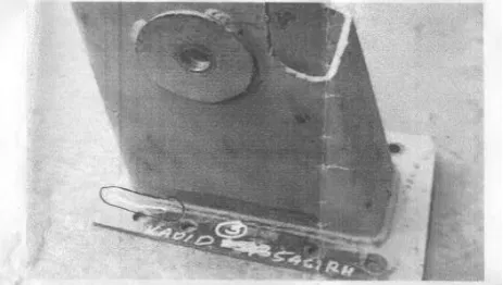
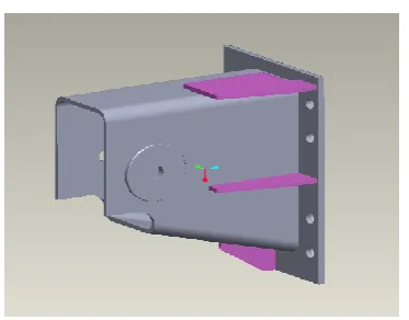
The schematic diagram of the Air suspension system is shown in the fig 1. It consist of four no of parts, these components are mounted in the chase except leaf spring. The component of bellow, shock absorber and bracket is mounted on the chases of the vehicle. The other end of the bellow and bracket is connected by using double stand leaf spring. The other end of shock absorber is fixed along with axel. This is the fixing arrangement of air suspension system. Whenever force exerted on the system the shock absorber and bellow absorb the force by means of leaf spring. One end of leaf spring is mounted below the bellow and other end is fixed with bracket. So whenever force exerted on the system it is also absorb by the bracket. The same process repeated when the vehicle is moving in the road due to road irregularity. Due to which bracket under goes fatigue load. So it leads to bend in the bracket and crack formation.
. Figure 1 Air suspension system
The failure component is shown in the fig. Fig 2 shows the bending over the leaf spring fixing area
Figure 2 Crack formation
Fig 3 shows the crack formation in the bracket at fixing with chases.
III. PROBLEM ANALYZING TECHNIQUE
To identify the real time problem we can use the Failure mode effect analysis (FMEA). Failure Modes and Effects Analysis (FMEA) is methodology for analyzing potential reliability problems early in the development cycle where it is easier to take actions to overcome these issues, thereby enhancing reliability through design. FMEA is used to identify potential failure modes, determine their effect on the operation of the product, and identify actions to mitigate the failures. A crucial step is anticipating what might go wrong with a product. While anticipating every failure mode is not possible, the development team should formulate as extensive a list of potential failure modes as possible.
IV. ANALYSIS OF EXISTING SYSTEM
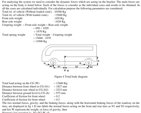
For analyzing the system we need to consider the dynamic forces which are acting on the bracket. The main forces are acting on the body is listed below. Each of the forces is consider as the individual cases and results to be obtained. In all the cases are calculated individually. For calculation purpose the following parameters are considered.
Total wt. of vehicle (Without loaded cond.) :10360 Kg Total wt. of vehicle (With loaded cond.) : 15660 Kg
Front axle weight : 650 Kg
Rear axle weight : 1020 Kg
Unspring weight = Front axle weight + Rear axle weight = 650 + 1020
= 1670 Kg
Total sprung weight = Total weight – Unspring weight = 15660 - 1670
= 13990 Kg
Figure 4 Total body diagram
Total load acting on the CG (W) = 15660 Kg Distance between front wheel to CG (b1) = 1827 mm Distance between rear wheel to CG (b2) = 2523 mm Distance between ground level to CG (h) = 975 mm Coefficient of friction for front wheel = 0.2 Coefficient of friction for front wheel = 0.5
The two normal forces, gravity, and the braking forces, along with the horizontal braking forces of the roadway on the tires, are displayed in fig 1If one labels the normal forces acting on the front and rear tires as N1 and N2 respectively, and lets W represent the weight, or force of gravity, then
Newton's law equation is: N1+N2-W =0
CG from the roadway. Adding clockwise torques and subtracting counterclockwise torques (where f1 and f2 are coefficients of friction):
b1N1 – b2N2 – hf1N1 – hf2N2 = 0
For creating the bump load calculating we need to consider following parameters. Total length of leaf spring : 930 mm
Radius of spring : 5307.8 mm Height of the spring : 30 mm Nominal thickness : 6.5 mm Material density : 1.7 g/cm3 Flexural strength : 400 MPa Flexural modulus of elasticity : 86 GPa Modulus of shear rigidity : 35 MPa Coefficient of compressibility : 160 MPa Load due to bellow:
Total load exerted by bellow : 30 bar => 75xE5 N/m2
So total load due to bellow : 30 X E5 * Area (3.14 X 0.125 X 0.125) : 1.473 E5 N
Consider vehicle is going 100 km/hr , and you applied the brakes and dropped to 25 km/hr in 3 seconds, and you assumed a constant braking force, we could calculate that force (given the weight of the vehicle, and ignoring air resistance and miscellaneous frictional decelerators).
Initial speed = 100 Km/hr= 27.78 m/sec Final speed = 25 Km/hr= 6.94 m/sec Time taken = 3 Sec
Deceleration (a) = (Initial speed – Final speed) / Total time taken = (27.78 – 6.94) /3 = 6.94 m/sec2
Braking force = m*a m --> Mass of the body (CG) a --> Deceleration
Braking force = 15660 x 6.94
= 108680.4 Kg m/Sec2 = 108680.4 N
= 108.68 KN
The results are obtained using working model 2D. The final results are given below. Refer fig 3, 4 & 5 1. Bump Loading Force = 14980N
2. Brake Loading Force = 25500N 3. Bump Couple Force = 273165Kg mm
= 2731650N mm = 2731.650N m Couple = Force X Distance Force = Couple/Distance
= 2731.651/.2 = 13658.255N 4. Corner Couple Force = 1483700Kg mm
=14837000N mm = 14837N m = 14837/.2= 74185N
V. PROCEDURE FOR ANALYZING
PREPROCESSING
The required modal for analyzing is designed in CAD model and it is transferred to ANSYS. The model is developed in CATIA and Converted in IGES Format and then that IGES format is imported ANSYS.
For analyzing in ANSYS we need to discrete the imported model in to no of elements. Since for our analyzing process we are using Solid 45.
The brief introduction about element is follows.
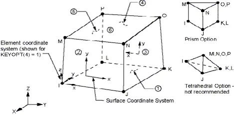
SOLID45 ELEMENT DESCRIPTION
SOLID45 is used for the 3-D modeling of solid structures. The element is defined by eight nodes having three degrees of freedom at each node: translations in the nodal x, y, and z directions. Figure 6 shows the Geometry of SOLID45
Figure 5 Geometry of SOLID45
MATERIAL PROPERTIES
In our bracket we are using following technical terms for arriving solutions. Material : CARBON STEEL C25
Yield Stress : 280 N/ mm2 Youngs Modulus : 2.05 E5(N/mm2) Posion Ratio : 0.3
In our model we are using 3D model. So we no need to select the Real constant. Because generally we use real constants for 2D model only.
MESHING
We used free meshing for analysis and the element used is Solid 45. The element type is discussed already. Total no of Element used for meshing is 72902. and the node is 583216.
LOAD
For analyzing the displacement is given as all degree of freedom in the mount hole of the bracket. And the boundary conditions are applied for the each cases individually. As already calculated forces are applied individually. The forces applied for the cases of Loads of Bump & Brake, and couple forces of Bump & Corner also Pretension-Corner. And the results are taken individually. Solve-After applying all the boundary conditions the component is sent in to get the solution. So each and every element is solved individually and the results are plotted.
POST PROCESSOR
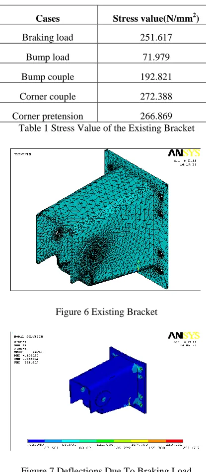
RESULT OF AN EXISTING SYSTEM
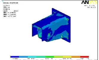
As per the procedure all the parameters are given in the ANSYS and the results are obtained for different type of cases. The results are shown below and Refer Fig 7 to 11
Cases Stress value(N/mm2)
Braking load 251.617
Bump load 71.979
Bump couple 192.821
Corner couple 272.388
Corner pretension 266.869 Table 1 Stress Value of the Existing Bracket
Figure 6 Existing Bracket
Figure 8 Deflection due to bump load
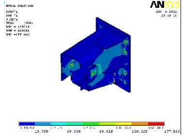
Figure 9 Deflection due to bump couple
Figure 10 Deflection Due To Corner Pretension
VI. IMPROVEMENT IN EXISTING DESIGN
For improving the existing model we need to reduce the stress vales in the leaf spring bracket. For that we can go for the material change. But if we suggested for new material then the concern have to maintain some inventory for the new type of material. Also we should not disturb the existing process flow. And the new development can be fitted for the existing operation and the existing vehicle. By considering the stress strain distribution in the product we need to improve the section modulus of the bracket. To reduce the stress strain in the bracket first we attack to increase the bellow diameter and increase the pressure inside. So that we can distribute more amount of force while load is acting upon the bracket. But the space is not enough for to keeping such a bulky bellow. So the bellow changing idea also dropped. On the other case the load which are transferred to the bracket from leaf spring can be minimize by adding highly damping capacity rubber between leaf spring eye to bracket tension bolt. But even high shore hardened rubber material has the low life cycle so couldn’t use such type of material. Also if the rubber failed then there will be a gap between both leaf spring and bolt. So it also makes unwanted noise.
With out changing the process and the material, by the addition of ribs in the side faces are giving better stress strain distribution on the leaf spring bracket. In this concept analyzing is started for the product. Firstly we produce 50 mm of bracket from the fixing area. But we don’t get optimum result. So we checked the same for different type of lengths. Also we have constrains to produce the stiffener. Because all the areas are covered by fasteners. If the stiffeners inserted in between the holes then it will hinder while bolt tightening. So stiffeners provided on the optimum places. The stiffeners height is finalized and the analyzing is done for that too as like the existing bracket analysis. All the parameters are already determined and the input condition is common for both cases. So existing values can be used for the same process also.
Result of the proposed bracket
Cases Stress value (N/mm2)
Braking load 231.991
Bump load 53.873
Bump couple 177.836
Corner couple 247.776
Corner pretension 229.031
TABLE 2 Stress Value of the Proposed Bracket
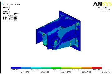
Figure 13 Deflection Due To Braking Load
Figure 14 Deflection Due To Bump Load
Figure 16 Deflection Due To Corner Pretension
Figure 17 Deflection Due To Corner Couple
FACTOR OF SAFETY
Factor of safety is a figure used in structural applications that provides a design margin over the theoretical design capacity. Also known as the safety factor, the factor of safety allows for uncertainty in the design process, such as calculations, strength of materials, duty and quality. The factor of safety is equal to the strength of the component divided by the load on the component. The number chosen as the safety factor depends on the materials and use of the item. Industry standards for design and engineering usually specify the allowable stress, or ultimate strength of a given material divided by the factor of safety, rather than use an arbitrary safety factor. This is because safety factors can be misleading and have been known to imply greater safety than is the case. A safety factor of two does not mean that an appliance can carry twice as much as it was designed for.
FOS = Yield Stress / Working Stress Loading
condition
Existing bracket Proposed bracket
Stress
N/mm2
FOS Stress
N/mm2
FOS
Braking
load 251.617 1.11 231.991 1.2 Bump
load 71.979 3.89 53.873 5.19 Bump
couple 192.821 1.45 177.836 1.57 Corner
couple 272.388 1.02 247.776 1.13 Corner
pretension 266.869 1.04 229.031 1.22
VII.CONCLUSION
The life cycle of the existing bracket is arrived using Finite Element Analysis. Various possibilities of improving the life cycle of the bracket is studied finally the addition of stiffeners in the bracket gives the increment in the number of cycles in the bracket without disturbing the Fit, Form and Function.
REFERENCES
1. Gillespie, T. D., ―Fundamentals of Vehicle Dynamics‖, Society of Automotive Engineers, Inc, 1992. 2. Liu, W., ―Nonlinear Analysis Theory of Single Leaf Steel Springs‖, SAE Paper 881744, 1988. 3. SAE, ―Manual on Design and Application of Leaf Spring‖, SAE HS788, APR80.
4. SAE, ―Spring Design Manual‖, SAE AE-21, 1996
5. SAE Standard, ―Leaf Springs for Motor Vehicle Suspension—Made to Customary U.S. Units—SAE 6. J510 NOV92‖, SAE Handbook, Vol. 2, p20.09, 1998.
7. Abrahamsson, P.; Salo, O.; Ronkainen, J.; Warsta, J. Agile Software Development Methods. 8. Review and Analysis. ESPOO (Technical Research Centre of Finland) 2002. VTT 9. Publications n. 478, 107 p.