Stress Rupture and Ballooning Behavior of Duplex Cladding for Nuclear Fuel
Rods
S.-H. Shann ~), F. T. Adams ~), H.-J. Sell 2), and A. Seibold 2)
1) FRAMATOME ANP Richland, Inc., Richland, Washington, USA 2) FRAMATOME ANP GmbH, Erlangen, Germany
A B S T R A C T
Duplex nuclear fuel rod cladding tubes have a thin external layer of a highly corrosion-resistant Zr-based alloy bonded to an inner Zircaloy-4 substrate layer. The external alloy layer may be fully optimized for maximum corrosion resistance, permitting operation of the fuel rod to the high exposure levels now sought by nuclear fuel managers for fuel cycle economy. Stress rupture and high temperature ballooning tests have been performed on production duplex cladding types to verify that the mechanical performance of the duplex cladding under design basis accident conditions meets regulatory acceptance criteria. Taken in sum, the test results demonstrate that the stress rupture and swelling behavior of the duplex cladding is largely determined by the properties of the substrate alloy, and can be made to coincide with those of Zircaloy-4. Thus, duplex cladding may be designed for improved mechanical and corrosion performance through independent specification of the substrate and external alloys.
INTRODUCTION
Various duplex cladding types have been irradiated in reactor to high exposure levels, showing good performance for some alloys and the duplex cladding concept [ 1 ]. A technical report on Duplex D4 (DX D4) cladding has been submitted to the NRC by FRAMATOME-ANP. Wide use of the Duplex D4 cladding in reactors is expected. This paper describes the stress rupture and ballooning tests performed on Duplex D4 cladding.
High-temperature stress rupture and ballooning tests are conducted to assess the cladding material behavior during an assumed loss-of-coolant accident (LOCA). The data obtained in the tests provide the experimental basis for the evaluation and calculation of the deformation and rupture of fuel rod cladding under postulated LOCA conditions. The tests described here were conducted with resistance-heated (ohmic heating) cladding tube sections from standard production lots. The tests were performed under carefully controlled conditions of temperature, temperature distribution (axial and circumferential), heating rate, and internal overpressure. Test results for DX D4 [1 ] cladding were compared to those for Zircaloy-4 cladding and other Duplex cladding to verify the applicability of the methodology developed for Zircaloy cladding to DX D4 cladding.
TEST DESCRIPTION
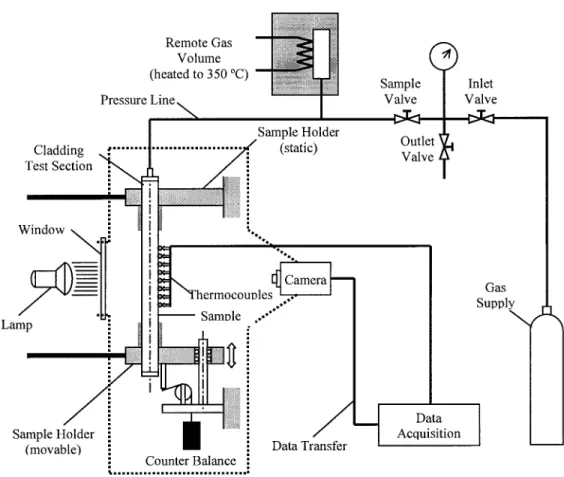
In the test equipment used for stress rupture and ballooning tests, the cladding sample is held in a vertical position between two fixtures. The lower fixture is free to move in the axial direction of the specimen to accommodate specimen length changes due to thermal expansion, ballooning, and swelling. The upper fixture remains stationary. Both fixtures are connected to an AC power supply which is used to heat the specimen. Specimen temperature is controlled with a programmable control unit connected to thermocouples welded to the test section. A schematic diagram of the test setup is shown in Figure 1.
The cladding sample is connected to a high-pressure argon gas supply through the upper end cap of the specimen. The initial total gas volume of the test system is approximately 40 cm 3, of which approximately 4 cm 3 occupies the initial free volume of the specimen and the remainder is maintained as a remote volume kept at 350°C. The gas inventory connected to the specimen remains constant during the test. The ratio of specimen volume to remote volume is such that temperature or volume changes in the specimen have relatively little effect on the internal pressure of the specimen.
A camera measures the outer diameter of the cladding specimen at the rate of three flames per second. The field of view of the camera covers the axial length of the sample where the temperature is measured and where swelling of the specimen is expected. A computer-controlled data acquisition system records temperature, specimen internal overpressure, and camera output for the duration of the test.
SMiRT 16, Washington DC, August 2001 Paper # 1444
S P E C I M E N D E S I G N
Each test specimen consists of a 238 mm-long section of cladding fitted with a welded lower end plug. The tube section is filled with annular A1203 ceramic pellets, centered by a stainless steel rod, that improve temperature uniformity around the circumference of the specimen. The outer diameter of the pellets is approximately 0.3 mm less than the inner diameter of the cladding tube, except for pellets in the middle of the specimen, where, over a length of 60 mm, pellets with a reduced diameter are used. The reduced-diameter pellets leave a diametral gap between pellets and cladding of 1.3 mm. An expansion gap for the pellets and steel rod is provided at the top of the specimen. An upper end plug, designed to connect to the pressurization system and remote gas volume, is welded to the upper end of the specimen. The upper and lower ends of the specimen are covered by support sleeves to prevent outward cladding creep and swelling in these regions. The presence of these support sleeves also results in an axial temperature distribution that leads to deformation and rupture within the center section of the specimen, where thermocouples record specimen temperature and a camera records deformation. A schematic diagram of the cladding tube specimen design is shown in Figure 2.
Figure 2 also shows the axial and circumferential locations of the Pt-PtRh thermocouples that are spot-welded to the cladding surface. Temperature variations around the circumference of the specimen are measured by three thermocouples at elevation "A." Data from the three thermocouples at elevation "B" are averaged and used for temperature control during the test. The remaining thermocouples are used to determine axial temperature variations.
T E S T I N G P R O C E D U R E
In preparation for stress rupture and ballooning tests of a cladding specimen, the outside diameter (OD), inside diameter (ID), and wall thickness variations for the specimen to be tested are measured and recorded. The specimen is then prepared as described in the section above, fitted with thermocouples, and installed in the test stand. All thermocouples are connected to the programmable control unit and the data acquisition system. The high-pressure argon supply is connected to the specimen and to a digital pressure gauge. Specimens are typically tested in air.
After all connections are checked, the specimen is heated to 350°C. The argon pressure is adjusted to provide the desired initial hoop stress in the cladding, then the argon supply is isolated from both the specimen and the remote- volume flask. The specimen is heated at a controlled heating rate to the predetermined test temperature and held until rupture occurs (stress rupture test), or the specimen may be heated at a controlled rate until it ruptures (transient test).
Typical changes in temperature and pressure as a function of time during these tests are shown in Figure 3. The temperature is increased from 350°C to the test temperature at a rate of 50 K/s; the pressure within the specimen remains nearly constant for the duration of the test. Changes in specimen circumferential strain are relatively slow at the start of the test and progress rapidly during the final phase. A typical strain diagram is shown in Figure 4.
C O M P A R A T I V E S T R E S S R U P T U R E B E H A V I O R
DX D4 specimens were prepared from cladding tubes from a production lot fabricated by FRAMATOME ANP, GmbH Germany from a co-extruded tube shell produced by Oremet Wah Chang (U.S.). The DX D4 and DXELS0.SB cladding types have been described in Reference 1.
The through-wall Zircaloy-4 cladding that had been tested previously [2] also came from various cladding lots manufactured by FRAMATOME ANP GmbH. Both "standard-tin" Zircaloy-4 cladding, with a tin content of approximately 1.5%, and "low-tin" Zircaloy-4 cladding, containing approximately 1.3% tin, have been tested. No discernable difference in the high-temperature stress rupture behavior of these two Zircaloy-4 variants was observed. Both types of cladding have compositions and other attributes that comply with the applicable ASTM specifications.
Stress rupture tests were performed on low-tin Zircaloy-4 cladding specimens at temperatures between 600°C and 900°C. All tests were conducted with the specimens at an initial temperature of 350°C. Specimens were heated at a rate of 50 K/s; specimen temperature uniformity was typically within 10 K.
Time to rupture as a function of initial specimen pressure for low-tin Zircaloy-4 cladding is shown in Figure 5. The plot shows good agreement between data from different lots of Zircaloy-4 cladding. Time tO rupture as a function of initial cladding hoop stress is shown in Figure 6 for both low-tin and standard-tin Zircaloy-4 cladding. Time to rupture is plotted as a function of initial hoop stress (rather than pressure) to facilitate the comparison of cladding tubes of different diameters. The results for low-tin cladding compare well with those for higher-tin cladding. The data for the higher-tin cladding are from earlier experiments and show a larger scatter due to a less accurate temperature control. Also shown in Figure 6 are the least-squares fit lines through the data at the different test temperatures. These least-squares correlations are the reference Zircaloy-4 correlations against which the behavior of Duplex cladding was evaluated.
Stress rupture measurements of DX D4 cladding were made in the same manner and with the same equipment used for the Zircaloy-4 measurements. Tests were conducted at temperatures between 700°C and 900°C. The DXELS0.8B and DX D4 data are shown in Figure 7 along with the Zircaloy-4 reference curves from Figure 6. Inspection of Figure 7 readily reveals that the time to rupture for pressurized tubing specimens ramped to temperatures between 600 and 900°C is essentially the same for Zircaloy-4, DXELS0.SB, and DX D4 claddings. Figure 7 further shows that the time to rupture of DX D4 cladding is actually slightly greater than that of through-wall Zircaloy-4 cladding.
C O M P A R A T I V E B A L L O O N I N G B E H A V I O R
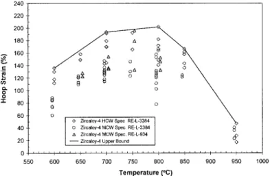
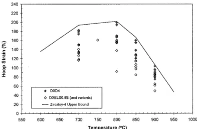
The hoop strain data (hoop strain at the rupture location as a function of test temperature) for several lots of standard Zircaloy-4 cladding (with a nominal tin level of 1.5%) are shown in Figure 8. The upper-bound curve for all of the data is indicated in the figure; this represents the maximum hoop strain reference curve for Zircaloy-4 cladding. Figure 9 shows a comparison of the Zircaloy-4 cladding reference curve and the rupture hoop strain data for low-tin Zircaloy-4 cladding. In Figure 10, the rupture hoop strains of DX D4 and DXELS0.SB cladding are compared to the Zircaloy-4 cladding reference curve.
The maximum hoop strain of DX D4 cladding at temperatures between 700°C and 900°C - the temperature range of greatest interest because superplastic deformation may take place at these temperatures - never exceeds the hoop strain of the reference Zircaloy-4 cladding. Fuel clad swelling in a LOCA transient is, therefore, no more severe for DX D4 cladding than for Zircaloy-4 cladding. Thus, analyses which indicate that fuel with Zircaloy-4 cladding would not suffer from coolant flow blockage during a transient are also applicable to fuel with DX D4 cladding, and would likewise indicate that flow blockage does not occur when DX D4 cladding is used.
S U M M A R Y
Stress rupture and ballooning tests were conducted to compare the behavior of Duplex D4 (DX D4), Duplex ELS0.8B, and standard through-wall Zircaloy-4 claddings. Over the testing temperature range (700 to 900°C), time to failure in the stress rupture tests for DX D4 cladding was the same as or slightly longer than for through-wall Zircaloy-4 cladding. The hoop strain at rupture for DX D4 cladding specimens was the same as or lower than for through-wall Zircaloy-4. These results indicate that it is conservative to model DX D4 with the same parameters as used for Zircaloy- 4.
R E F E R E N C E
1. Garzaolli, F., Manzel, R., and Reynolds, R.S., "A Decade Irradiation Experience with Duplex Cladding,"
International Topical Meeting on Light Water Reactor Fuel Performance, Park City, Utah, U.S.A., April 10-13, 2000.
2. Sell, H.-J., Eberle, R., Seibold, A., and Van Swam, L.F., "Duplex Cladding; Siemens Answer to the Requirements of Extended Burnup in PWRs," Proc. of the International Symposium Fontevraud III, Vol. 2, pp 744-751, Fontevraud, France, September 12-16, 1994.
Remote Gas
Volume
(heated to 350 °C)
Pressure Line,~
[iiiii i!iiiiiiii
i! ~ii ii!
Iiii
,ii
Sample Holder
Lamp
TeCsltaded~tng
n , , ~ ;
... ~
(static)
Window
/ l!iiiiiii
iii i ii iiii}iiiii [ iiiiiil ! ~ Camera
~] "Therm°c°u°les I.. -''
~
SamNe ...""
i I ...
Sample Holder i
I / '
[ii(movable)
:
:
Counter Balance •
% nm m • m mn u m m o • m mum aul nu num am am m m m • m m m m n u mu • m m
/
Data Transfer
Sample
Valve
Outlet
Valve
Data
Acquisition
Inlet
Valve
Gas Supply
\,x~,
Pressure Upper End Expansion Support Steel Rod Ceramic Pellets (reduced OD) Cladding Support Sleeve Ceramic
Lower End Plu
(dimension are in mm)
T
60 238 Thermocouple Measurement Plane:--Y-- H
10
- - - - G
10
F 10
- - - - A1-A3
10 Control TC B l-B3
10
m ~ C
10
- - - - D
10
--A-- E
Thermocouple Positions on Circumference
120 ° A3, B3, G,E"
_ A 1 , B 1 ,
A2, B2, F, D C,H
120 °
Fig. 2 S t r e s s R u p t u r e a n d B a l l o o n i n g S p e c i m e n D e s i g n (left) a n d T h e r m o c o u p l e L o c a t i o n s ( c e n t e r a n d r i g h t )
Fig. 3
900 800
L
700 19. 600 "~ 500 400 300 t ~ I I I I I I I I I I I _ J Temperature
P r e s s u r e
I
~ ~ S p e c i m e n T e m p e r a t u r e [ S p e c i m e n P r e s s u r e ' I ' I ~ I ' I ' I ' I ' I ' I ' J, ' I ' I "0 10 20 30 40 50 60 70 80 90 100 110
Elapsed Time (s)
2.0 1.9 1.8 1.7 a.
,,.,,
1.6
1.5
13.
1.4
1.3 ~.
1.2
1.1
1.0
20
160
140
120
o~" 100
e -
'N 80 L
6O
Fig. 4
B u r s t S t r a i n
. . .
Time to Rupture
' ~ " T - ' - ' I ~ I ' I ' I ' I ~ I ' "1
0 20 40 60 80 100 120 140 160
E l a p s e d T i m e (s)
Typical Evolution of Strain During a Stress Rupture Test
Fig. 5
,ooo
900oc O0°C
500- °C 600~C
.... 200- '" -
• ~ 85ooc \ , [] r. 8 o
g~ 5°
o 5 0 - o
~) .r..i
E 750o C ~ , ~
i=
800°C ~
\
2O . 825°C % - -
]~ 850°C "~
900°C
Data Regression
5 i i i ,
6 10 20 30 50 100 200
S p e c i m e n P r e s s u r e (bar)
Time to Rupture of Low-Tin Zircaloy-4 Cladding as a Function of Temperature and Initial Specimen Pressure
Fig. 6
1,000
~ k '°~°c * \
5OO i c 7SO°C
v~ 200 ~ ~ ~ o
~E 50 O ~,:,, :' \ TemperatuFe (°C)
~ k Nominal Range
~.~:~ ~. , ~ 600 592- 607
\
\
20 N,~C"~ "~\ \ \ 750 739-756
. . o o "" ~" 825 823 - 830
10
. Dala_~:gre.:s;on ~ ) S t a n d a r d . T i n ( 1 5 ~ X ~ ~ 900 886 - 901
5 i 1 ,i r • ,
6 10 20 30 50 1 O0 200
I n i t i a l H o o p S t r e s s (MPa)
Time to Rupture of Standard-Tin (1.5% Sn) and Low-Tin (1.3% Sn) Zircaloy-4 Cladding as a Function
of Temperature and Initial Cladding Hoop Stress (These data are used to establish the least-squares fit
1 , 0 0 0 , . . . , - -
200-t ^^^.~.. \ \
~ u u O ~ . " 850oC
lOO- ~
o \
10. 4~ D X D 4
0 D X E L S 0 . 8 B ( a n d v a r i a n t s ) Zircaloy-4 Reference
5 i
6 1 0
ooc
oC
\
20 30 50 100 200
Initial H o o p Stress (MPa)
Fig. 7
Fig. 8
Time to Rupture of DX D4 and DXELS0.8B Cladding as a Function of Temperature and Initial Cladding
Hoop Stress. (The lines represent the Zircaloy-4 cladding~reference correlation established earlier.)
2 4 0 2 2 O 2OO
180
. . . . 1 6 0
e- 140
120 o
Q .
O 1 0 0
O
= 80
6 0
_o
[
2 0 Z c I y - 4
0 . . . . [ . . . . I . . . . I . . . . I ' ' ~ ~ I L ~ ' ' I . . . . ; . . . . ', . . . .
550 600 650 700 750 800 850 900 950 1000
T e m p e r a t u r e (°C)
Hoop Strain at Rupture of Zircaloy-4 Cladding with a Nominal Tin Content of 1.5%. (The upper-bound
curve is the Zircaloy-4 cladding reference maximum hoop strain.)
Fig. 9
2 4 0 2 2 0 200
180
. - . 1 6 0 .= 14o
m L
,~ 120 --
o 100 O
'1- 6 0 8 0 ! o
<> Z i r c a l o y - 4 H C W S p e c R E - L - 3 3 8 4 4 0 0 Z i r c a l o y - 4 M C W S p e c . R E - L - 3 3 8 4
A Z i r c a l o y - 4 M C W S p e c . R E - L - 9 3 4 .~:, 2 0 ~ Z i r c a l o y - 4 U p p e r B o u n d ~ ~>
0 . . . . ', ' ' ' : . . . . : . . . . : ' ' ' : . . . . I ' ' ' ~ I j ' ' ' ' , . . . .
550 600 650 700 750 800 850 900 950 1000
T e m p e r a t u r e (°C)
Hoop Strain at Rupture of Low-Tin Zircaloy-4 Cladding Compared to the Standard Zircaloy-4 Cladding Reference Maximum Hoop Strain
~!i~!:~ ~
2 4 o 2 2 o 2 O O 1 8 0 .... 1 6 0 1 4 0 .=_
L . ~ 1 2 0 (J0
e~ O 1 0 0 O "t" 8O
@
60
D X D 4 4 O
O D X E L S 0 . 8 B ( a n d v a r i a n t s ) 2 0 ~ Z i r c a l o y - 4 U p p e r B o u n d
0 . . . . I . . . . I . . . . I . . . . I . . . . I ' ' ' ' I ' ' ' ' ; . . . . ; . . . . 5 5 0 6 0 0 6 5 0 7 0 0 7 5 0 8 0 0 8 5 0 9 0 0 9 5 0 1 0 0 0
Temperature ( ° C )
Fig. 10 Rupture Hoop Strain of DX D4 and DXELS0.8B Cladding Compared to the Standard Zircaloy-4 Cladding Reference Maximum Hoop Strain
"~,~!~i~ ~ ~ : ii.,i:,~
![Fig. 5 ,ooo 900oc O0°C 500- °C 600~C .... 200- '" - • ~ 85ooc \ , [] r. 8 o g~ 5° o 5 0 - o ~) .r..i E 750o C ~ , ~ i= 800°C ~ \ 2O](https://thumb-us.123doks.com/thumbv2/123dok_us/1725055.1220024/6.894.253.650.71.330/fig-ooo-oc-o-c-c-ooc-e.webp)