Structural Analysis and Evaluation on the Containment Structure of the
Pressurized Water Reactor Plants with Consideration of the Aging Effects
Zhongcheng Li1, Jinfeng Chen2
1
Professor Senior Engineer, China Nuclear Power Design Company, Shenzhen, CHINA
2 Engineer, China Nuclear Power Design Company, Shenzhen, CHINA
ABSTRACT: The containment structure of a nuclear power plant (NPP) with pressurized water reactor (PWR) is very critical and the last physical barrier and it is irreplaceable equipment, such that the containment design service life is directly related to the nuclear power plant life. Earlier, the 1000MW PWR nuclear power plants were all designed with the design life period of 40-year considered in China, but now the 60-year requirement of the service age of a plant is put forward in order to improve the operation period of nuclear power plant.
Therefore, a comprehensive analysis of the impact on the containment structure durability of several factors is conducted and the main influence factors are extracted as follows: the long term effect of the material properties; loads change caused by design aging change; comprehensive durability evaluation on structure materials. Firstly, the design basis for a 60-year design life should be determined according to the requirement. Then, re-evaluate loads and strengths of the materials etc. to ensure its applicability and adjustment method if needed. At the same time, because of the increase of the design service life, the analysis of the parameters closely related to time factor, such as shrinkage, creep, size of the prestressed force loss effect based on the design life of 60 years should be performed. Finally, the technical requirements for structural durability to meet 60-year old are explored and proposed in this paper.
As an example, a PWR containment in China is introduced and evaluated based on the 60-year service age, and the evaluation methodology, steps and results are released in this paper. It could be a very good reference, and could also be applied to other assessments on service life extending of the civil structures of nuclear facilities.
1. PREFACE
The service life of a nuclear power plant is an important factor closely related to its safety and economy. If safety is ensured, longer service lifetime brings better economy. The requirements for the site conditions of a NPP are strict. If the design lifetime of a NPP can be extended, the economy of the NPP can be greatly improved and the selected site can be fully used. Then the site selection pressure can also be relieved.
The investigation and analysis of the problems in operation, causes of ageing and degradation or in service components in PWR show that the lifetime of irreplaceable and hard-renewable components affect and restrict the lifetime of NPP to a great extent. These components include reactor pressure vessel (PRV), reactor internals, containment and some construction.
Containment is the third and the last barrier and can shield radiations during operation or accidents. Containments also protect reactor from external accidents and are of great importance to the safety of the environment and the public. Containment provide the sealing, shielding and supporting functions during the lifetime and should maintain even after decommissioning.
2. RESEARCH IN CHINA AND ABROAD
operation and maintenance data, and got the aging mechanisms and evaluation technology. Containments are extremely difficult to be replaced. The factors causing aging of containments are fatigue and corrosion.
Since 1985, the Nuclear Regulatory Commission (NRC) of the United States has conducted research on aging of NPPs and assessments for continuing service life. The research shows that the design life of irreplaceable devices such as containments is a key factor for ensuring the design lifetime of NPPs. The special research on containment structure and components of PWRs shows that the containment structure consists of the concrete structure, structural steel and liner, reinforcing steel and prestressing tendons. The aging mechanisms and aging effects are researched respectively. The parts that are non-significant and that need be evaluated more are differentiated and relevant procedures are provided.
France is the second largest nuclear power generation country in the world, next to the United States. In France about 75% of gross generated power is from nuclear power. In 1985 EDF started the research on aging management, which is called “service life project”. The purpose of the project is to reach the lifetime successfully during the design phase, generally 40 years, then on this basis, to research the feasibility of 60 years of service life. The following research is implemented: (1) assessment of age-related degradation of structures and materials; (2) evaluation on changes of operation conditions; (3) safety measures required for service life extending; (4) evaluation on economy of service life extending.
To sum up, the countries that developed nuclear power earliest in the world have conducted research on aging management and service life extension of NPPs, for example, Japan, United States, and France. And common results have realized that structures extremely difficult to be replaced is the important factor deciding the service lifetime of NPPs and an important part in the aging research. 60-year service life of containments can greatly improve the economy of NPPs.
In China, the design life of existing 1000MW PWR nuclear power plants is 40 years. The research on 60-year service life of containments of the NPPs started late. Therefore, it is necessary to conduct a comprehensive analysis.
3. ANALYSIS METHODS OF CONTAINMENT ON THE 60-YEAR SERVICE LIFE
Many factors affect the design life of containments. The main influence factors are extracted as follows: the long term effect of the material properties; loads change caused by design aging change; comprehensive durability evaluation on structure materials, etc. Based on the preceding factors and using Chinese Codes, analysis and evaluation on the design of containments are conducted by ANSYS.
Firstly, the design basis should be determined according to the requirements of 60-year design life of containments. Then, re-evaluate loads and strengths of the materials etc. to ensure its applicability and adjustment method if needed. At the same time, because of the increase of the design service life, the analysis of the parameters closely related to time factor, such as shrinkage, creep, size of the prestressed force loss effect should be performed based on the design life of 60 years. Finally, the technical requirements for structural durability to meet 60-year old are explored and proposed.
In this case, containment FEM models need to be built to analyze and evaluate the containment structure on the 60-year design life, using the 60-year design criteria and result of prestressed force loss. The research is conducted by reference to Chinese codes and nuclear power specifications in China. At the same time, the analysis on prestressed force loss and durability is also calculated by reference documents and some European codes.
Now, a 1000MW PWR containment in China is introduced and evaluated based on the 60-year service age. The evaluation methodology, analysis steps and results are described.
4. STRUCTURAL ANALYSIS EXAMPLES OF CONTAINMENT ON THE 60-YEAR SERVICE LIFE
4.1 Containment Introduction
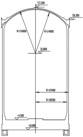
temperature is 145C. The inner diameter of the cylinder shell is 37m; the wall thickness of the cylinder is 0.9m; the radius of the flat dome connecting to the cylinder is 24m; the thickness of the dome is 0.8m. On the cylinder, many penetrations of different sizes exist. Figure 1 shows the containment elevation.
Figure 1. Containment Elevation
4.2 Loads and Load Combinations
The load cases to be considered in containment design include normal load cases, abnormal load cases, normal climatic load cases, extreme climatic load cases, emission of internal missiles and external aggressions. For details, see table 1.
Table 1: List of Load Cases Considered in the Structural Design of Containment
Symbol Load Type Symbol Load Type
D Permanent loads Ta Effect of design temperature
L Live loads W Reference wind pressure load on the site
F Prestressing Wt Effect of tornado
T0 Temperature effects during
construction, operation or shutdown
E1 Operational safety ground motion
R0 Reactions induced by the equipment
during normal operation or shutdown E2 Ultimate safety ground motion
Pt Effect of test pressure A2 Effect of external pressure wave(no
generated by tornado)
Tt Effect of test temperature A3 Effect of external missile(no generated by
tornado) Pa Effect of design pressure (relative)
NRC Regulatory Guide 1.60.The horizontal component of the ultimate safety ground motion is characterized by the horizontal design response spectrum NRC, scaled to a zero-period acceleration of 0.2g. The vertical component of the ultimate safety ground motion is characterized by the same horizontal design response spectrum NRC, scaled to a zero-period acceleration of 0.133g.
The acceleration values at different levels of the containment are obtained through time history analysis and applied to the FEM model as static load. Three components of earthquake are assembled by NEWMARK method. During time history analysis, the soil-structures interactions are modeled by impedance functions and the containment adopts the equivalent mass-beam model. The earthquake action is transferred to the structure basis through centralized springs and dampers.
The load combinations of the concrete containment include the load combinations for checking the allowable stress and ultimate limit states of concrete. The load combinations for checking the allowable stress include: D+L+F+W+T0 in the prestressing phase, D+L+F+Pt in the overall structure
testing phase, and D+L+F+ T0+Pv in normal operation.
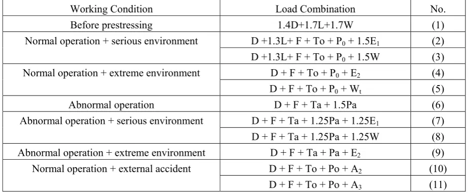
Table 2: List of Load Combinations Considered in the Structural Capacity Design of Containment
Working Condition Load Combination No.
Before prestressing 1.4D+1.7L+1.7W (1)
D +1.3L+ F + To + P0 + 1.5E1 (2)
Normal operation + serious environment
D +1.3L+ F + To + P0 + 1.5W (3)
D + F + To + P0 + E2 (4)
Normal operation + extreme environment
D + F + To + P0 + Wt (5)
Abnormal operation D + F + Ta + 1.5Pa (6)
D + F + Ta + 1.25Pa + 1.25E1 (7)
Abnormal operation + serious environment
D + F + Ta + 1.25Pa + 1.25W (8)
Abnormal operation + extreme environment D + F + Ta + Pa + E2 (9)
D + F + To + Po + A2 (10)
Normal operation + external accident
D + F + To + Po + A3 (11)
4.3 Loss of Prestress
It is important to correctly estimate the prestressed force loss in the design of prestressed concrete structural members. The change of the containment design life may lead to changes of time-dependent loss of prestress, for example: concrete shrinkage, creeping and stress relaxation that affect prestress design. Therefore, the change must be reevaluated so that more exact tendons prestress can be used as an input condition for the overall containment calculation.
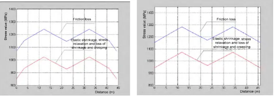
During calculation, the loss of prestress caused by the following factors must be considered: friction between tendons and channel, anchorage seating, tendon shortening, elastic compression of concrete, stress relaxation of tendon and concrete shrinkage and creeping. Figure 2, Figure 3, and Figure 4 show the stress state in tendons.
a. Internal tendons b. External tendons Figure 2. Diagram of Stress State in Horizontal Tendons
Figure 3. Diagram of Stress State in Vertical Tendons
a SET1 b SET3 Figure 4. Diagram of Stress State in Dome Tendons
ANSYS is used to build FEM models and analyze loads. The containment FEM models include three entrances (the diameter >2m): two personnel air lock (the diameter= 2.9m), the central levels are 1.15m and 9.15m; one equipment hatch(the diameter= 7.4m), the central level is 22.9m.
The containment shares a concrete raft foundation with the internal structure; the foundation floor is 5.5m thick and is rigid. It can be assumed that the containment is fixed on the foundation floor. Containment FEM models are built from the top of the foundation floor and restricted the degree freedoms of nodes at the bottom.
In containment FEM models, SOLID45 is used to simulate the concrete parts such as containment cylindrical wall, dome, and vertical ribs, LINK8 is used to simulate prestressed tendons, and SHELL43 is used to simulate the penetration sleeves. The cylindrical wall in thickness direction is divided into three layers of units in FEM model; the vertical ribs is divided into five layers of units; the cylinder wall is divided into 288 units around the circle direction and 223 units in height direction; the dome in thickness direction is divided into two layers of units.
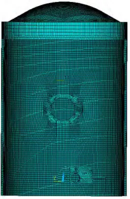
The cables in the containment include: 144 vertical 36T16 tendons, 223 horizontal 19T16 tendons, and 3 groups of three-way dome 19T16 tendons. The cables distribution is complex. Before building the FEM model, tendons need to be differentiated: for regular parts using the method in which prestressed tendons share nodes with concrete units; for complex area using tendons and concrete separately built and then the node associated with constraint equation and create coupling so that tendons are consistent with distortion of surrounding concrete. Figure 5 shows a containment model created by ANSYS. Figure 6 shows the prestressed tendons model.
Figure 5. Containment Structural Model
Figure 6. Tendons Models
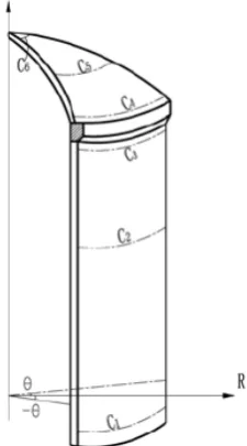
First of all, analyze every single load case and combine the results ,then according to EJ/T 926-95, calculate the allowable stress and check reinforcement at the typical sections. Select the sections at levels -0.5m, 30.0m and 45.0m as the typical sections. For the dome, select three sections along the latitude direction. Figure 7 shows the positions of the typical sections.
Figure 7. Schematic Diagram of Typical Section
4.4.2 Stress Checking Results
In each typical section, select the first and the third primary stress and check the tension stress and pressure stress of fibers at the end of the section. For typical sections at cylinder, use the hoop stress σy and vertical stress σz in the global coordinate system to obtain the average membrane stress and check
the (average) membrane pressure stress or tension stress. Table 3 lists the checking results of allowable stress of the (D+L+F+W+T0) combination in the prestressing phase.
Table 3: Result List of Permissible Stress Checking (Unit: MPa)
Section Position σc0.7fck σt0.7ftk σcy0.35fck σty0 σcz0.35fck σtz0
-0.5m -19.5 1.70 -7.36 -1.865 -9.06 -9.06
30.0m -19.4 1.29 -9.06 -7.51 -9.79 -5.975
45.0m -17.4 1.648 -4.075 -4.075 -7.98 -7.98
52.0m -8.43 0.605 -5.865 -5.78 -8.41 -8.2
54.0m -10.57 0.625 -9.495 -9.325 -10.62 -10.475
56.0m -10.08 0.759 -10.07 -9.865 -9.995 -9.89
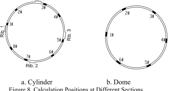
For each typical section, extract internal force and check reinforcement in different positions. Select eight different positions on the cylinder and six different positions on the dome for checking. Figure 8 shows the positions.
Rib. 2 Rib. 4
a. Cylinder b. Dome Figure 8. Calculation Positions at Different Sections
Each cylinder position has a horizontal section and a vertical section. The horizontal section is used to check the bearing capacity of the cylinder along the height direction, and the vertical section is used to check the bearing capacity of the cylinder along the circular direction. Each position of the dome also has two sections. The stressing performance of two axes in the spherical coordinate system at the original point is similar to that of the two sections in cylinder.
The analysis results show that the containment is in compression state; the stress on the vertical section is similar to the axial compressed components; the stress on the horizontal section is similar to that of eccentric stressed components. The procedure for checking the bearing capacity of sections is complex. The specific procedure is as follows:
1) Extract the stress on nodes of relevant positions and integrate the stress along different paths to obtain the internal forces of the sections.
2) In a section of the unit length, make the interactive curve of eccentric compression (Mu-Nu curve) of the section based on actual reinforcement area. The points on the curve indicate the combinations of axial force and bending moment that may cause damage.
3) Compare the internal force (M, N) extracted on sections in different combinations with the Mu-Nu curve. If the internal forces are in the Mu-Nu curve, the bearing capacity of the sections meets requirements. Based on which the stressing performance of sections is determined.
In addition, for the internal force on sections obtained in step (1), the deviation of geometric dimensions must be taken into consideration as the additional bending moment generated in some load combinations. Only the areas of common reinforcement are considered during calculation of the Mu-Nu curves.
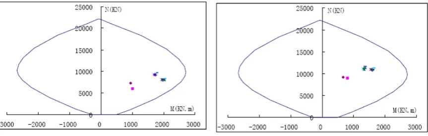
Figure 9. Sketch Map of Reinforcing Bars at Level 30.0m
a. Combination 6: D+F+1.5Pa+Ta b. Combination 9: D+F+ Pa+Ta+ E2 Figure 10. Diagram of Calculation Results in Horizontal Sections at Level 30.0m
Table 4: List of Calculation Forces in Vertical Sections
Axial Pressure Value N (kN) Comb.
1# 2# 3# 4# 5# 6# 7# 8#
Section Bearing Capacity (kN)
Comb. 6 7947.89 7078.46 7892.02 8431.07 7767.16 7535.68 6345.48 6228.79 21339.34
Comb. 9 10208.19 9084.48 9856.78 10398.04 9737.16 9501.77 8328.52 8214.85 21339.34
4.5 Durability Requirement
Durability design is an important aspect that ensures the service life of structures. The durability requirements for concrete in terms of 60-year design service life of containments are evaluated by reference to the 100-year design service life.
The requirements include the durability requirement of concrete structures, multiple protective measures for the prestress system, and anti-corrosion requirement of liner. In addition, importance must be attached to the construction requirements and maintenance requirements , repair and inspection during use.
5. CONCLUSION
containments in terms of the 60-year design service life, correctly analyzes and evaluates the prestressed force loss effect, and checks the bearing capacity of typical sections.
2) The analysis methods described in this paper provide reference for the research on the service life of prestressed structures and design of containments of NPPs and also lay a foundation for service life extension of existing NPPs in the future.
3) This document involves only concrete structures. Other parts such as penetration sleeves and hatchs(E/H,A/L) also need to be evaluated so that the containment performance can be evaluated fully.
REFERENCES
Atomic Energy Commission (1973), “NRC RG 1.60-1973, Design Response Spectra for Seismic Design of Nuclear Power Plants”, USA .
Dong Z.F. and Zhao C.C. (2010), “Analysis on Prestress Friction and Anchorage Loss of Nuclear Power Plants”, Prestress Technology, Jan. 24-29.
EJ/T926-95(1995), Code for prestressed concrete containments of PWR nuclear power plants, China
National Nuclear Corporation
European Committee for Standardization (2008), “EN 1992-1-1, EUROCODE 2: Design of Concrete Structures”.
Fan L.C. et al.(2004), Guide to Concrete Structure Durability and Construction, China Building Industry
Press.
GB/T 500476-2008(2008), Code for durability design of concrete structures, Ministry of Construction in
People’s Republic of China
GB 50010-2010(2010), Code for design of concrete structures, Ministry of Construction in People’s
Republic of China
GB 50009-2006(2006), Load code for the design of building Structures, Ministry of Construction in
People’s Republic of China
GB 50267-97(1997), Code for seismic design of nuclear power plants . Ministry of Construction in
People’s Republic of China
JTG D62-2004(2004), Code for Design of Highway Reinforced Concrete and Prestressed Concrete
Bridges and Culverts, Ministry of Communications in People’s Republic of China
Li Z.C. and Dong Z.F.(2010). “Site Applicability Study on the Nuclear Island Buildings Design for the Pressurized Water Reactor Station with 1000MW Class,” Nuclear Power Engineering, Oct 9-13.
Nuclear Energy Institute (1995),NEI 95-10, Industry Guideline for Implementing the Requirements of 10 CFR Part 54 - License Renewal Rule.
Nuclear Regulatory Commission (1999), NUREG-1611, Aging Management of Nuclear Power Plant