Comparative Analysis for Bending and
Contact Stresses of Girth Gear By Using
AGMA Standard& Finite Element Analysis
Amol Deshpande
1, Abhay Utpat
2P.G. Student, Department of Mechanical Engineering,S.V.E.R.I College, Pandharpur, Maharashtra, India1 Professor, Department of Mechanical Engineering, Fabtech Engineering College, Sangola, Maharashtra, India2
ABSTRACT:Gearing is one of the most critical components in a mechanical power transmission system, and in most industrial rotating machinery. Traditionally, gears are designed using AGMA (American Gear Manufacturers Association) or ISO (International Organization for Standardization) standards and followed by manufacturing. FEA has beena useful tool in recent days not only to validate design; it can also use to optimize design. The present work is aimedat analytical designof girth gear byusing AGMA standard. Bending & contact stresses on the gear teeth are calculated.The validation of thestresses is done by usingANSYSsoftware. The values of the bending stress and contact stress determined using AGMA found to be in agreement with ANSYS results and corresponding error observed is less than 5%.
KEYWORDS:Bending stress, contact stress, Girth gear, AGMA, FEA.
I. INTRODUCTION
Girth gears are large ring gears which are normally fitted to the outside of the mills or kilns to provide the primary rotational drive. Girth gears are considered to be one of the most important components in the entire gear drive assembly of such mills. For designing Girth Gears and pinions, today several standards are available.The most common and popular standards are AGMA 6004, AGMA 2101and ISO 6336. The two things that form the test of the gear design are surface durability (pitting) and tooth bending strength. Girth gears can be manufactured in 2, 3, 4, 5, 6 or 8 or more segments and for both T and Y section gears. A girth gear can be single or double pinion driven. A pinion is manufactured as a single part with an integrated shaft. The pinion can also be separate and mounted on a separate shaft, supported by bearings. The girth gear drive system is a "lifeline" for cement producers. With the increased emphasis on operating efficiency, the dependable and reliable operation of these drive systems is essential. No one needs the cost or headaches associated with unscheduled downtime or inefficient machinery operation [1].
There isa great deal of research on gear design and analysis. The design data required for gear design has been widely available from many textbooks and journals for nearly three decades. Dudley [2], Buckingham [3], Merritt [4], and Tuplin [5] have spent enormous effort in detail the procedure involved in the design of gears. Kasuba [6] determined dynamic load factors for gears that were heavily loaded based on one and two degrees of freedom models.
AGMA based or ISO based calculation method of gear strength is commonly used. None of these authors have givenany importance to a computer-aided approach.
IIMATERIAL&METHOD
Material:-
In this paper, a pair of girth gear & pinion (used for cement mill application) is selected for analysis. Specification of girth gear& pinionis as follows:
No. of teeth on pinion, TP=27 No of teeth on gear, TG= 202 Face width of gear, b=750mm
Center distance, C=3480 mm
Module, m= 30
Mill speed, NG= 17.1 RPM Backlash = 2.2 to 2.5
Power = 2200 KW
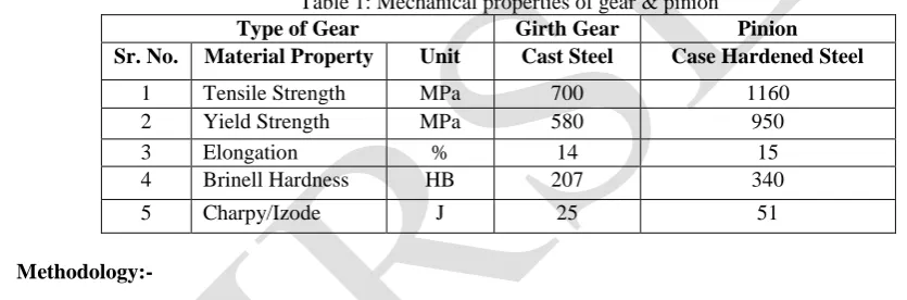
Material used for girth gear is high strength cast steelGr.2 CS 700 which is equivalent to IS: 2644 Gr.2& for pinion is case hardened steel 18CrNiMo6. Mechanical properties of the material for gear & pinion are given in table no. 1.
Table 1: Mechanical properties of gear & pinion
Type of Gear Girth Gear Pinion
Sr. No. Material Property Unit Cast Steel Case Hardened Steel
1 Tensile Strength MPa 700 1160 2 Yield Strength MPa 580 950 3 Elongation % 14 15 4 Brinell Hardness HB 207 340 5 Charpy/Izode J 25 51
Methodology:-
A pair of gear teeth is subject to two types of cyclic stresses: bending stresses inducing bending fatigue and contact stress causing contact fatigue. Both these types of stresses may not attain their maximum values at the same point of contact fatigue. These types of failures can be minimized by careful analysis of the problem during the design stage and creating proper tooth surface profile with proper manufacturing methods. In general, gear analysis is multidisciplinary, including calculations related to the tooth stresses and to tribological failures such as wear or scoring.
In the present study, bending & contact stress analysis of Girth gear was carried out through following three steps.
1) Theoretical calculation of bending & contact stresses by the analytical method(AGMA standard)
The tooth load carrying capacity was calculated according to the AGMA standard. According to AGMA,the bending failure is avoided by considering the beam strength and the pitting failure (contact stress) is avoided by considering the wear strength. Gear design will be safe if Eq. 1 and 2 are satisfied.
Bending strength criteria: 𝛔𝛔all (1)
𝛔 = (3)
𝛔c = ZE (4)
𝛔all =
Z N F t
Y
Y
Y
S
S
(5)𝛔c all =
Z W N H c
Y
Y
Z
Z
S
S
(6) NomenclatureKo is the overload factorKv is the dynamic load factor
Ks is the size factor KH is the load distribution factor
KB is the rim thickness factor YJ is the geometry factor for bending strength
ZE is an elastic coefficient (N/mm2) ZR is the surface condition factor
dW1 is the pitch diameter of the pinionZ1is the geometry factor for pitting resistance
b is the face width of the narrowest memberm is the module
St is allowable bending stress YN is the stress cycle factor for bending
Yθis temperature factor YZ is the reliability factor
SF is the AGMA factor of safety Sc is allowable contact stress
ZN is stress life factor ZW is hardness ratio factor for pitting
SH is the AGMA factor of safety
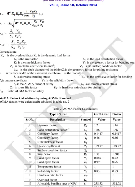
AGMA Factor Calculations by using AGMA Standard
AGMA factors were calculated& tabulated in table no. 2
Table 2: AGMA Factor Calculations
Type of Gear Girth Gear Pinion
Sr.No. Description Symbol Value Value
1 Dynamic factor KV 1.2 1.14
2 Load distribution factor KH 1.86 1.86
3 Geometry factor ZI 0.1417 0.1417
4 Geometry factor YJ 0.46 0.46
5 Rim thickness factor KB 1 1
6 Elastic coefficient ZE 189.77 189.77
7 Surface condition factor ZR 1 1
8 Size factor KS 1.51 1.502
9 Load cycle factor YN 0.889 0.72
10 Load cycle factor ZN 0.99 0.95
11 Temperature factor Yθ 1 1
12 Reliability factor YZ 0.83 0.83
13 Hardness ratio factor ZW 1 1
14 Overload factor Ko 1 1
15 Allowable bending stress (MPa) St 258.52 352.02
Wt = Power Velocity=
(2200 × 1000)
5.4974 = 400189.1803 N
Wt = 400189.1803 N
AGMA based design is carried out for pinion as it is smaller in size,
Bending Criteria:
Putting all factors in Eq. 3:
σ = 400189.1803 × 1 × 1.14 × 1.502 × 1 750 × 30×
1.86 × 0.65 0.46 σ = 80. 13 MPa
Similarly, putting all factors in Eq. 5:
σall =
352.02 × 0.72 1 × 0.83
σall = 305.37 Mpa
As (<all is satisfied the design is safe for bending loading.
Pitting or Contact Criteria:
Putting all factors in Eq. 4:
σC = 189.77 × 400189.1803 × 1 × 1.14 × 1.502 ×
1.86 820.61 × 750×
1 0.1417 σC= 725. 47 MPa
Similarly, putting all factors in Eq. 6:
σc,all =
1056.4 × 1 × 1 1 × 0.83
σc,all = 1272.77 MPa
As c<c, all is satisfied the design is safe from pitting or contact loading.
Hence, AGMA based safe design of girth spur gear is obtained for bending & contact stresses.
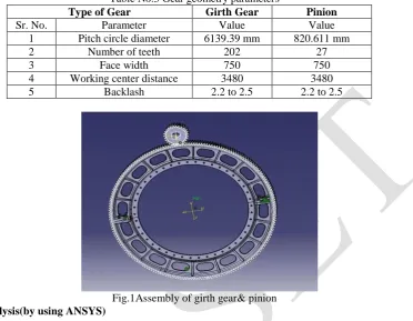
2) Parametric modelling of girth gear & pinion
Table No.3 Gear geometry parameters
Type of Gear Girth Gear Pinion
Sr. No. Parameter Value Value 1 Pitch circle diameter 6139.39 mm 820.611 mm 2 Number of teeth 202 27 3 Face width 750 750 4 Working center distance 3480 3480 5 Backlash 2.2 to 2.5 2.2 to 2.5
Fig.1Assembly of girth gear& pinion
3) Stress Analysis(by using ANSYS)
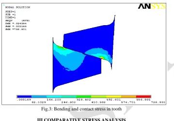
After completing the 3D CAD model in CATIA, the same model is imported in ANSYS. The stress analysis of girth gear is done by using ANSYS.This work uses simplified modelsfor tooth strength analysis. Fig. 2(a) shows the geometry of the tooth in mating condition created in ANSYS. 2D tooth geometry is meshed using 8-node SHELL elements. Thickness of shell is equal to face width of the tooth. Fig. 2(b) shows meshed model contains 5433 number of nodes and 1717 number of elements. As weight is applied as a load and contact defined.Analysis is performed and stress results are obtained.
The stress contour in gear and pinion tooth is as shown in fig.3. Bending stress is checked at the root of the tooth whereas contact stress is checked along the contact region. From analysis bending stress observed was 82.10 MPa and contact stress was 738.90 MPa
Fig.3: Bending and contact stress in tooth
III COMPARATIVE STRESS ANALYSIS
For the comparative stress analysis, the bending & contact stresses calculated by using AGMA standard & ANSYS software are presented in table no.4. The values of the bending stress and contact stress determined using AGMA & ANSYS, both arevery close. The percentage error between the stress values calculated by AGMA & ANSYS was observedvery less.
Table 4: Comparison of AGMA and ANSYS results
Type of Stress in MPA
AGMA ANSYS % Error
Bending 80.13 82.10 2.39
Contact 725.47 738.90 1.81
IV.CONCLUSION
The bending and contact stress analysis was carried out using AGMA standard and ANSYS software. Based on the study, the following conclusions are drawn.
AGMA based design approach for stress analysis is formulated for girth gears.
Successfully developed a parametric model in CATIA which reduces modelling efforts.
AGMA based design calculations of girth gear are validated using ANSYS.
REFERENCES
[1] Dude, W.H. (1985) Cement data book, Volume I, 3rd Edition. Beverage GMBH, Berlin [2] Dudley DW, “Gear Handbook”, McGraw Hill (1958)
[3] Buckingham E, “Spur Gears”, McGraw Hill (1962) [4] Merritt HE, “Gears”, Pitman Publishing (1964)
[5] Tuplin WA, “Gear Design”, The Machinery Publishing Co (1962)
[6] Kasuba, R., “An Analytical and experimental Study of dynamic Loads on Spur Gear Teeth”, Ph.D., University of Illinois
[7] Anand B Rathod, Vinay J Patel, PM Agrawal, “A Parametric Modeling of Spur Gear using Pro-Engineer”, National Conference on Recent Trends in Engineering & Technology, 13-14 May 2011
[8] Mike Renfro, “Modeling Gear Teeth in Pro/Engineer Wildfire 4.0”, May-2010.
[9] Fang Feng, Hui Pan, Guojun Hu, “Pro/E Based Parametric Design of Spur Gears”, Advanced Materials Research, 201-203, 2011: 790-794. [10] Errichello, R., 1979, “State-of-art review: gear dynamics”, Trans. ASME, J. Mech. Des., 101 (3), 368-372.
[11] Ozguven, H. N., Houser. D. R., 1988, “Mathematical models used in gear dynamics”, Sound Vibrations., 121,383-411.
[12] Vijayarangan S., Ganesan N. 1994, “Static Contact Stress Analysis of A Spur Gear Tooth Using the Finite Element Method Including Friction Effects”, Computer & Structures, Vol. 51 No. 6 pp767-770