JETLEY,RAOUL. Reasoning of Safety-Critical Medical Devices using Formal Methods. (Under the
direction of Associate Professor S. Purushothaman Iyer).
The design and functional complexity of medical devices have increased during the past 50 years,
evolving from the use of a metronome circuit for the initial cardiac pacemaker to functions that
include electrocardiogram analysis, laser surgery, and intravenous delivery systems that adjust
dosages based on patient feedback. As device functionality becomes more intricate, concerns
arise regarding efficacy, safety and reliability. It thus becomes imperative to adopt a standard or
methodology to ensure that the possibility of any defect or malfunction in these devices is
minimized.
It is with these facts in view that regulatory bodies are interested in investigating mechanisms to
certify such medical devices. These organizations advocate the use of formal method techniques
to evaluate safety-critical medical systems. The use of formal methods is keenly debated though,
with most manufacturers claiming that they are arduous and time-consuming.
In this thesis, we evaluate the feasibility of formal method techniques for medical devices. More
specifically, we discuss our experiences in modeling and verification of the specifications for a
typical medical system called the Computer Aided Resuscitation Algorithm (CARA) using two
formal methods based tools, UPPAAL and Spin.
We find that the use of UPPAAL and Spin for the analysis of the CARA system yields several
anomalies and inconsistencies, hitherto undetected. The results from the two tools are found to
be in accordance, and the effort involved comparable to conventional techniques. Based on our
results, we conclude that formal methods provide a feasible and effective means for reasoning of
Reasoning of Safety-Critical Medical Devices
using Formal Methods
by
Raoul Jetley
A dissertation submitted in partial satisfaction of the requirements for the degree of Master of Science
in
[Computer Science]
in the
GRADUATE SCHOOL at
NC STATE UNIVERSITY 2002
DR.S.PURUSHOTHAMAN IYER Associate Profesor
Chair of Advisory Committee
DR.ANNIE I.ANTÓN Assistant Professor
Biography
Raoul Jetley was born on October 28, 1976, in New Delhi, India. He spent most of his formative years in the quiet little town of Jamnagar, and earned his High School diploma from the Naval Public School, Chanakyapuri in 1994. He graduated with a Bachelor’s degree in Computer Science from Bombay University in 1998. He spent the next couple of years developing Re-engineering tools and web applications at Shreyas Business Solutions Pvt. Ltd., Bombay. In the fall of 2000 he enrolled for the M.S. degree in Computer Science at North Carolina State University, and shortly thereafter began working on his thesis under the direction of Dr. Purushothaman Iyer.
Acknowledgements
Table of Contents
List of Figures...vi
List of Tables ...vii
Chapter 1. Introduction ... 1
1.1 HISTORICAL BACKGROUND... 1
1.2 STRUCTURE OF THIS DOCUMENT... 3
1.3 THE MEDICAL DEVICE AS AN ENTITY... 4
1.4 SAFETY-CRITICAL COMPUTER SYSTEMS... 5
Chapter 2. Formal Methods Overview... 6
2.1 MODELING... 6
2.1.1 Automaton... 7
2.1.2 *-Automata... 7
2.1.3ω-Automata... 7
2.1.4 Büchi automata... 8
2.1.5 Timed Automata... 8
2.2 FORMAL ANALYSIS... 8
2.2.1 Finite-State Models ... 9
2.2.2 Temporal Logic... 9
2.2.3 Linear Temporal Logic (LTL)... 10
2.3 TOOLS FOR SPECIFICATION AND ANALYSIS –UPPAAL AND SPIN... 10
Chapter 3. The CARA Infusion Pump System... 12
3.1 OVERVIEW... 12
3.2 SYSTEM COMPONENTS... 13
3.3 MODES OF OPERATION... 13
3.4 TYPICAL OPERATIONAL SETUP... 14
3.5 ALARM CONDITIONS... 17
3.6 HAZARD ANALYSIS... 18
3.7 BENEFITS OF USING MATHEMATICAL MODELS FOR CARA ... 19
Chapter 4. The UPPAAL Model... 21
4.1 THE UPPAALMODEL CHECKER... 21
4.1.1 Introduction... 21
4.1.2 An overview of UPPAAL... 22
4.1.3 The Description of Models in UPPAAL... 23
4.1.3.1. Syntax... 24
4.1.3.2 Guards over Clock and Data Variables... 25
4.1.3.3 Reset-Operations... 25
4.1.3.4 Synchronization using Channels... 25
4.1.3.5 Semantics... 26
4.1.3.6 Model Checking... 27
4.1.4 Optimizations... 29
4.2 MODELING CARAUSING UPPAAL... 29
4.2.1 The CARA Process. ... 30
4.2.2 The Pump Process... 30
4.2.3 The Alarm Process... 31
4.2.4 The Observers... 31
4.3 SIMULATION USING UPPAAL... 32
4.4 VERIFICATION USING UPPAAL ... 32
5.1 THE SPIN MODEL CHECKER... 33
5.1.1 Operation... 34
5.1.2 The Nested Depth-First Search Algorithm... 35
5.1.3 Büchi Automata from LTL Formulae... 37
5.1.4 Partial Order Reduction and Memory Management... 38
5.2 MODELING CARA USING SPIN... 39
5.2.1 The Cara Process... 39
5.2.2 The Pump Process... 40
5.2.3 The CalculateVoltage Process... 40
5.2.4 The Alarm process... 40
5.2.5 Other processes... 40
5.3 SIMULATION USING SPIN... 41
5.4 VERIFICATION USING SPIN... 41
Chapter 6. Results and Conclusion ... 42
6.1 SIMULATION ISSUES... 43
6.2 FINDINGS... 44
6.2.1 Anomalies ... 45
6.2.2 Missing Specifications... 46
6.2.3 Inconsistency between documents... 47
6.3 COMPARISON BETWEEN SPIN AND UPPAAL... 48
6.3.1 Comparison based on Ease of Use ... 49
6.3.2 Comparison based on the Implementation of the tools... 50
6.3.3 Comparison based on Efficacy of the tools... 51
6.4 CONCLUSIONS... 52
Appendix A: The CARA Model in UPPAAL... 55
Appendix B: The CARA Model in Spin... 63
Appendix C: LTL Formulae ... 73
Appendix D: Screen shot of a Simulation in UPPAAL ... 75
Appendix E: Screen shot of a Simulation in Spin ... 76
List of Figures
Figure 1.1 ICOM Model for Modeling and Verifying the CARA System ... 3
Figure 3.1 Open Loop Operation In Manual Mode... 13
Figure 3.2 Closed Loop Operation In Autocontrol Mode ... 14
Figure 3.3 The Test Boundary For The CARA System ... 18
Figure 4.1. The Client/Server Architecture Used In UPPAAL... 22
Figure 4.2. Graphical Description Of The Fischers Mutual Exclusion Protocol ... 23
Figure 4.3. Textual Description Of The Fischers Mutual Exclusion Protocol ... 24
Figure 4.4. An Example UPPAAL Model... 26
Figure 4.5. The Algorithm For Symbolic Reachability Analysis ... 28
Figure 5.1 The Structure Of Spin Simulation And Verification... 34
Figure 5.2 The Grammar for Linear Temporal Logic ... 37
List of Tables
Table 3.1 Alarm Priorities And Silence Times... 17
Table 6.1 Comparison of Errors Detected by UPPAAL and Spin ... 51
Table 6.2 Effort Required For Modeling The CARA System In Spin ... 52
Chapter 1. Introduction
1.1
Historical Background
Medical devices are an important part of health care. Yet they are an extraordinarily
heterogeneous category of products. The term “medical device” includes such technologically simple articles as ice bags and tongue depressors on one end of the continuum and very
sophisticated articles such as pacemakers and surgical lasers on the other end. Perhaps it is this
diversity of products coupled with the sheer number of different devices that makes the
development of effective and efficient standards a unique challenge for regulatory bodies.
The Food and Drug Administration (FDA) is one of the organizations interested in investigating
mechanisms by which to evaluate and certify safety-critical medical devices. The FDA believes
that the rigorous employment of modern disciplined Software Engineering practice and the use
of formal mathematical models can significantly improve software quality, and strongly
advocates the use of formal method techniques to evaluate safety-critical medical systems. As a
means to substantiate the FDA’s claim, we were asked by the Walter Reed Army Institute of
Research (WRAIR) to examine the suitability of formal methods as applied to a typical medical
system, called Computer Aided Resuscitation Algorithm (CARA).
In this thesis, we discuss our experiences in the modeling and verification (analysis) of the
requirements for the CARA system using two formal methods based tools, UPPAAL∗ and Spin.
To perform this task, we were provided with a set of documents giving the requirements for the
CARA system. These included:
A Functional Specifications Document. A plain text document giving an overview of the
CARA system and its components and basic functions. It also provided a list of use-case and
error-case scenarios.
A Tagged Requirements Document. The official specification document for CARA, which
contained a list of numbered specifications, with related requirements clubbed together.
A Hazard Analysis Draft. A description of the various malfunctions and error conditions,
like loss of power, pump failure, incorrect response that could occur in the system. It also
described the system boundary and interfaces for the CARA system.
A Q&A Document. A list of questions that came up during the drafting of the tagged
requirements document, with the corresponding responses. This document served as an
FAQ (Frequently Asked Questions) list for the CARA system.
The aim of this thesis is to perform a qualitative analysis of formal methods based tools. Two
tools were employed for this analysis: UPPAAL and Spin. Both tools are used to model CARA
and then verify the model, checking for errors and inconsistencies. Results from the two case
studies are compared, and the effort for each is calculated. Lastly, with all the results in hand, we
assess whether the use of formal methods is justified in the verification of a safety-critical medical
system like CARA.
The modeling and analysis of the CARA system were performed keeping in mind the skill level
of a typical analyst designing or verifying such a medical system. The CARA project was
undertaken by an analyst (the author of this thesis) who possessed no prior experience with
either of the two tools. In addition, the requirement documents provided were also typical of
those available to an analyst working on such a system as they included several vague or
conflicting requirements.
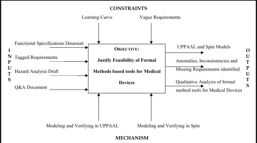
Figure 1.1 gives an ICOM model illustrating the Inputs, Constraints, Outputs, and Mechanism for
1.2
Structure of this Document
This thesis is organized by chapters that discuss formal method mechanisms and their use as
applied to the CARA system. The next two sections in this chapter examine typical medical and
safety-critical devices and the challenges faced in ensuring their dependability. Chapter 2
provides a brief overview of formal methods theory, and gives an introduction to some of the
automata that form the basis for the tools used for designing CARA. Chapter 3 describes the
CARA system in detail, listing the various components, typical operation and error conditions
that need to be checked. Chapters 4 and 5 illustrate the operation of the UPPAAL and Spin tools
respectively, and describe the design of the CARA system in each. Finally, Chapter 6 lists the
result obtained through UPPAAL and Spin, and summarizes the qualitative analysis of formal
methods based tools.
Figure 1.1 ICOM Model for Modeling and Verifying the CARA System
CONSTRAINTS
Functional Specifications Doument
Q&A Document
UPPAAL and Spin Models
Qualitative Analysis of formal method tools for Medical Devices Anomalies, Inconsistencies and Missing Requirements identified
Modeling and Verifying in UPPAAL Modeling and Verifying in Spin Tagged Requirements
Hazard Analysis Draft
Learning Curve Vague Requirements
I N P U T S O U T P U T S MECHANISM OBJECTIVE:
Justify Feasibility of Formal
Methods based tools for Medical
1.3
The Medical Device as an Entity
There are as many different definitions for a medical device as there are regulatory and standards
organizations. Though the definitions may differ in verbiage, they have a common thread of
content. The Medical Device Directives [30] define a medical device as:
“Any instrument, appliance, apparatus, material or other article, whether used alone or in combination, including the software necessary for its proper application, intended by the manufacturer to be used for
human beings for the purpose of:
- diagnosis, prevention, monitoring, treatment or alleviation of disease;
- diagnosis, monitoring, alleviation of or compensation for an injury or handicap;
- inquiry, replacement or modification of the anatomy or of a physiological process;
- control of conception;
and which does not achieve its principal intended action in or on the human body by pharmacological,
immunological, or metabolic means, but which may be assisted in its function by such means.”
One important feature of the definition is the inclusion of the term ‘software’. The software definition could probably be given further interpretation, but we limit its interpretation to mean:
1. software intended to control the function of a device is a medical device;
2. software for patient records or other administrative purposes is not a device;
3. software which is built into a device, e.g., software in an electro-cardio graphic monitor used
to drive a display, is clearly an integral part of the medical device; and
4. a software update sold by the manufacturer, or a variation sold by a software house, is a
medical device in its own right [19, 3].
The patient is the ultimate consumer of medical devices, from the simplest cotton swab to the
most sophisticated monitoring devices. However, with the exception of some over-the-counter
1.4
Safety-Critical Computer Systems
Most computer systems consist of many sub-components, which are tightly coupled and have
highly complex interactions. The binding of application to operating system to architecture is a
prime example of a tightly coupled system. When such a system is further embedded within
larger contexts, such as command and control systems, the probability of failure quickly
approaches one. Myers [31] estimates that there are approximately 3.3 software errors per
thousand lines of code in large software systems. This figure is not surprising given that there
are as many as 1020 unique end-to-end paths in a moderate-sized program [35]. What is worse is
that not all errors in software are created equal, as small errors do not necessarily have small
effects. The picture becomes much bleaker when the software/hardware interactions in
computer systems are taken into account, as is the case in most medical devices. In two studies
[21, 25], nearly 10% of all software errors and 35% of all software failures identified were later
found to be hardware-related, such as transient faults corrupting data. In fact, it was shown that
hardware could fail three times as often as software under some circumstances (e.g. in
aeronautical systems) [6].
Despite these considerable problems, the advantages of the added versatility and flexibility
provided by digital systems as opposed to other means are overwhelming and, therefore,
insufficiently understood software and hardware are often used. However implemented, we
require that safety-critical systems be dependable. The most effective means to avoid accidents
during a system's operation is to eliminate or reduce dangers during the design and
development, not afterwards when the complexity becomes overwhelming. It is at this stage,
Chapter 2. Formal Methods Overview
The process of applying formal methods to a chosen application typically involves the following
phases: defining the scope, developing requirements, modeling, specification, analysis
(validation), and documentation [26]. The term Modeling refers to the mathematical
representation of a system underlying the system’s specification. Formal Specification is simply
the characterization of a planned or existing system expressed in a formal language. Formal
Analysis involves validation of the specifications, proving key properties and invariants, and
establishing the consistency of axioms. Formal Documentation is used to trace specification to
requirements (high-level design), track level of effort, and where relevant, collect cost/benefit
data. The distinction between phases is somewhat artificial and should not be taken too literally,
since there is a considerable amount of overlap between them, and each phase generally leads
into the next. Thus, even though we shall be looking mainly at modeling and analysis in this
document, aspects of characterization and specification are also covered herein.
2.1
Modeling
A model defines a mathematical representation suitable for formalizing the application domain
and for calculating and predicting the behavior of the application in that context. Models can be
defined for discrete or continuous domains. The discrete domain models are in turn framed in
terms of four broad classes: functional, abstract state machine, automata-based, and
object-oriented. Automata-based models were found to be best suited for the CARA system, since they
allow separate process and functions to be defined while still permitting abstract state
2.1.1 Automaton
An automaton (plural automata) is a finite-state transition system consisting of a set of states and
a set of state-to-state transitions that occur on input symbols chosen from a given alphabet. There
are four types of automata relevant to this thesis. These are explained briefly below.
2.1.2 *-Automata
Automata may be deterministic, meaning that there is a unique transition from a given state on a
given input, or nondeterministic, meaning that there are zero, one, or more such transitions.
Formally, a deterministic finite automaton is defined as a 5-tuple (S; Σ; δ; s0; F), where S is a finite
set of states, Σ is a finite input alphabet, δ is a transition function that maps S x Σ to S, s0 is the
initial state, and F
⊆
S is the set of final states. A nondeterministic finite automaton is similarlydefined as a 5-tuple, the only difference being that δ is a map from S x Σ to
P
(S), the power set ofS. In other words, δ (s, a) is the set of all states s’ such that there is a transition labeled a from s to
s’. Conventional or *-automata accept only finite words and can express state invariants, that is,
safety properties or properties “at a state”, but not eventualities or fairness constraints [26].
2.1.3 ω-Automata
To accommodate eventualities, it is necessary to use a class of automata that accepts infinite
words (sequences), the so-called ω-automata. Like a conventional automaton, an ω-automaton
consists of a set of states, an input alphabet, a transition relation, and a distinguished initial state.
The difference between the two classes of automata occurs in the definition of acceptance.
Acceptance for a conventional automaton is defined in terms of a final state. Since the notion of
final state is not useful for a class of machines that accepts infinite words, acceptance must be
where S, Σ, and s0 are as defined above,
F
is an acceptance condition, and δ : S x Σ→P
(S) is atransition function.
The sum of M on a word w=a0a1a2… is an infinite sequence of states s0 s1 s2 . . .∈ S that begins in s0
and has the following property: ∀i >= 1, ∃ai ∈ Σ : δ (si, ai) = si+1. A word w is accepted by M
provided some final state is visited infinitely after in some sum of M on w. The infinitary set of a
sequence s0 s1 s2 … ∈ Sω, written as inf (s0 s1 s2 …), is the set of all states that appear infinitely
many times in the sequence [14].
2.1.4 Büchi automata
A Büchi automaton M is an ω-automaton where the acceptance condition,
F
, is defined asfollows. F
⊆
S is a set of states (as in the case of a *-automata) and a path p is accepted by M if inf(p)
∩
F≠ φ
[14].2.1.5 Timed Automata
Timed automata are a generalization of ω-automata and are used to model real-time systems over
time. Like ω-automata, timed automata generate (accept) infinite sequences of states. However,
timed automata must also satisfy timing requirements and produce (accept) timed state
sequences. Timed automata may be given various semantic interpretations, including
point-based strictly-monotonic real-time (the original interpretation), interval-point-based variants,
interleaving, fictitious clock, and/or synchronicity [2].
2.2
Formal Analysis
Formal analysis refers to a broad range of tool-based techniques that can be used singly or in
combination to explore, debug, and verify formal specifications, and to predict, calculate, and
in focus, method, and degree of formality, include direct execution, simulation, and animation;
finite-state methods (state exploration and model checking); and theorem proving and proof
checking. We concentrate on finite state models in this document, and give the background for
these here.
2.2.1 Finite-State Models
Finite-state methods are techniques for the automatic verification of finite-state systems or of
infinite-state systems that can be “reduced” by virtue of certain structural symmetries or uniformities. Given a formula specifying a desired system property, these methods determine its
truth or falsity in a specific finite model (rather than proving its validity for all models).
2.2.2 Temporal Logic
Temporal logic (also known as tense logic) [33, 7] augments the standard operators of
propositional logic with tense operators that are used to formalize time-dependent conditions.
The simplest temporal logic adds just two operators: the (weak) future operator, F, and the
(weak) past operator, P. The formula Fq is true in the present if q is true at some time in the
future and, similarly, the formula Pq is true in the present if q is true at some time in the past.
These operators can be combined to assert quite complex statements about time-dependent
phenomena. For example, q ⇒ FPq can be interpreted as “if q holds in the present, than at some time in the future q will have held in the past” [29]. The duals of these operators, ¬F¬, usually abbreviated G and ¬P¬, usually abbreviated H, yield the corresponding strong future and past
operators. Gq ≡ ¬F¬ q means that q is true at every moment in the future, and Hq ≡ ¬P¬ q
means that q is true at every moment in the past.
A temporal logic system consists of a complete set of axioms and inference rules for proving all
in general, are typically given a model theoretic semantics known as possible worlds semantics.
A model in this semantics is usually referred to as a Kripke model [13]. The basic idea of Kripke
semantics is to relativize the truth of a statement to temporal stages or states. Accordingly, a
statement is not simply true, but true at a particular state. The states are temporally ordered,
with the type of temporal order determined by the choice of axioms. The set of states in an
interpretation represents not only past states, but all accessible (possible) future states [7].
2.2.3 Linear Temporal Logic (LTL)
Linear time corresponds to the usual notion of time as a linearly ordered set, measured either
with the real or the natural numbers. The temporal order relation < is total, that is,
antisymmetric, transitive, and comparable (comparability means that for all states s1 and s2 in the
same execution sequence, either s1 < s2 or s2 < s1 or s1 = s2).
Linear temporal logic is typically extended by two additional operators, the until operator and
the since operator, abbreviated U and S, respectively.
φ
Uϕ
is true in state sj if there is some statesk such that sj < sk and
ϕ
is true in sk, and for all si, such that sj < si < sk,φ
is true in state si.Intuitively,
ϕ
holds at some time in the future, until which timeφ
holds. Similarly,φ
Sϕ
is true instate sj just in case there is some state sk such that sk < sj and
ϕ
is true in sk, and for all si, such thatsk < si < sj,
φ
is true in state si.2.3
Tools for Specification and Analysis – UPPAAL and Spin
Various tools are available based on different mathematical models for discrete and continuous
domains. Two such tools are used for specification (through modeling) and analysis of the
Spin is a generic verification system that supports the design and verification of asynchronous
process systems [23]. A system in Spin is described in a modeling language called Promela and
consists of one or more user-defined process templates, and process instantiations. Each process
template is translated by Spin into a finite automaton. The global behavior of the concurrent
system is obtained by computing an asynchronous interleaving product of automata, one
automaton per asynchronous process behavior. The resulting global system behavior is itself
again represented by an automaton, referred to as the state space of the system, and can easily be
represented as a graph. UPPAAL on the other hand is a toolbox for modeling, simulation and
verification of real-time systems, based on constraint-solving and on-the-fly techniques. To
facilitate modeling, UPPAAL provides a graphical interface [4] to define system descriptions as
networks of timed automata.
Both tools make use of Linear Temporal Logic (LTL) formulae to verify against the specified
model, although the implementations of the verification mechanisms differ. UPPAAL performs
verification with the help of a modified Reachability algorithm, whereas Spin computes the
synchronous product of the given claim and the global state space. This allows Spin to provide a
more comprehensive state-search facility.
Chapter 3. The CARA Infusion Pump System
3.1
Overview
The Computer Assisted Resuscitation Algorithm (CARA) is a closed loop software system that
drives a high output infusion pump (M100) used for fluid resuscitation of patients suffering from
conditions that lead to hypotension. The system uses blood pressure as the control for a
proportional closed-loop control algorithm. The CARA system is fielded on up to 3 platforms:
Life Support for Trauma and Transport (LSTAT), DataPak and Warfighter Physiological Status
Monitor (WPSM) collectively known as Hosts. The software needs to accommodate various
blood pressure inputs (e.g. arterial line, noninvasive cuff, pulse wave, etc).
The requirements for the CARA system are specified by the four documents mentioned in
Chapter 1. These documents can be obtained from Dr. Fred Pearce of the Walter Reed Army
Institute of Research.
The CARA is intended to support primary intravenous fluid resuscitation therapy to rapidly
restore intravascular volume and blood pressure in patients with clinical shock, hypotension, and
hypoperfusion states as a result of hemorrhagic blood loss, occult hemorrhage, neurogenic shock
and septic shock. The normal use is to attach a physiological monitoring device (PMD) like the
LSTAT or DataPak to the patient by a caregiver, identified as a Medic, Nurse, or Doctor. Once
the PMD is attached, vital signs are taken and registered to the CARA. The CARA responds
according to the condition of the patient, which is determined by the patient’s blood pressure.
The CARA’s intended use is for combat casualties but at times civilians may also be treated. The
CARA is limited to providing the care attributed to the feature set of the M100 infusion pump [8].
These solutions include, but are not limited to dextrose, water, lactated Ringers, saline, dextran,
and Hespan.
3.2
System Components
The CARA is an integrated software system that drives or interacts with several other
sub-systems. These include an FDA approved M100 pump, the Host, an alarm unit, a user interface
that includes a graphical display with a set of buttons for the medic, and a log file.
3.3
Modes of Operation
At any given point in time, the CARA can be in one of three modes. These include
The WAIT mode, during which all the subsystems are available but the pump is not
connected to the Host.
The Manual operating mode, during which the pump is connected to the Host and the pump
is infusing the fluid. However, in this mode, the medic still has (manual) control over the
system.
The Autocontrol mode, in which the medic relinquishes control and the system is operated
entirely according to the CARA algorithm.
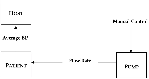
The Manual mode is characterized by an open loop, as depicted in Figure 3.1.
Average BP
H
OSTP
UMPP
ATIENT Flow RateManual Control
As shown in the figure, the Host and the pump are both plugged in, and the pump is infusing
fluids to the patient. The Host collects the blood pressure readings and other vital signs from the
patient, and simply displays them on the screen for the medic. The medic has complete manual
control over the pump, and it is he alone that manages the flow rate and volume to be infused by
the pump. The Alarm Unit, Log File and the User Interface are all operational in this mode.
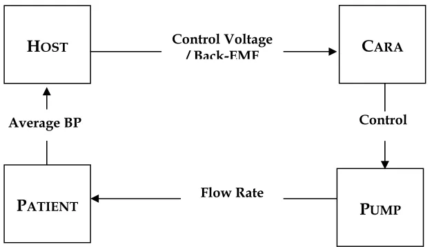
In the Autocontrol mode, which is characterized by a closed loop, as shown in Figure 3.2, the
pump still continues infusion of fluids to the patient, and the Host still collects readings from the
patient. However, now the Host not only displays and logs all its readings, but it also feeds a
control voltage back to the CARA. Based on the readings from the Host, the CARA drives the
pump, adjusting the flow rate and the volume of the fluid to be infused. The medic still has the
ability to terminate the Autocontrol mode and revert back to the Manual mode, but ideally the
CARA should be able to manage all situations.
3.4
Typical Operational Setup
The CARA is operational whenever the Host is powered on. CARA monitors the pump plug to
determine when a pump is plugged in. When a pump is plugged in, the Host supplies power to
the pump. The CARA monitors the pump air lock line and impedance signals as long as the
C
ARAAverage BP
H
OSTP
UMPP
ATIENT Flow RateControl Control Voltage
/ Back-EMF
pump remains plugged in. If a fault is detected, an appropriate error message is displayed, a
short audible alarm sounds and a visible alarm indicator is lit. The CARA monitors the
back-EMF line from the pump to keep track of infused fluids when the pump is operating in Manual
mode. If back-EMF is detected in Manual mode, the volume infused per minute is calculated and
logged into a resuscitation file with the time and trended on a graphical display. The fact that the
pump is in Manual mode is also recorded in the resuscitation log file and shown on the display.
The CARA is able to use blood pressure (BP) from any source to control its algorithm. Blood
pressure sources have the following priority for use: arterial line, other beat-to-beat pressures
(pulse wave transmission, etc.), and cuff pressures. If the CARA detects a blood pressure during
Manual mode, it logs the pressure to the resuscitation file every minute. If the source reports the
blood pressure more than once a minute, an average over the minute is stored. The source and
the time of the blood pressure are also recorded. The blood pressure that is stored to file is also
graphed on the display unit along with the flow rate.
When the system is in Manual mode, a display screen is presented to the user that has the
graphical representation of the infused volume and the blood pressure (if any). The display
screen also numerically shows the current flow rate, volume infused and current blood pressure.
The display also allows the medic to enter a blood pressure to which the CARA aims to titrate
(called the ‘set point’). Once a blood pressure has been entered a ‘Start’ button becomes active allowing closed loop infusion to begin. If the Start button is selected, the CARA enters the
Autocontrol mode based on the currently available blood pressure.
If the blood pressure is an arterial line, a 15-second average is calculated and used for control. If
an arterial line is not available, then other blood pressure sources are used. If the pulse wave
signal is detected, the CARA immediately begins to calibrate the pulse wave using an average of
5 cuff pressures taken one minute apart. It is expected that a valid pulse wave pressure reading
minutes using the above procedure. If a cuff pressure is used the CARA sets a blood pressure
frequency based on the average BP calculated so far. If the CARA can not get a valid blood
pressure reading, a 5-second audible alarm sounds along with a visible indicator and an error
message to the display unit. The pump remains in Manual mode until the validity of the blood
pressure is established. Once a valid blood pressure has been established, the proportional
controller calculates a voltage that drives the pump. A notation indicating that the system is in
Autocontrol mode is made on the display and in the resuscitation log file. Also, a horizontal line
indicating the blood pressure set point is shown on the graphical display.
When the CARA is in Autocontrol mode a ‘Terminate Autocontrol’ button is made available. Whenever this button is selected, the Autocontrol mode is immediately terminated. The drive
voltage to the pump is set to 0 and control is returned to the pump. A notation that the system is
in Manual mode is made to the display unit and to the resuscitation log file.
If the pump is unplugged while there is no back-EMF detected, the system does not respond. If
unplugged while back-EMF is detected, a 3-second audible alarm sounds, a visible indicator
lights up, appropriate messages are displayed on the display unit and noted in the log file.
Similarly, if the pump is unplugged during Autocontrol mode, a 5-second audible alarm sounds,
a visible indicator lights up, and notations are made to the display unit and log file.
While in Autocontrol mode, if a beat-to-beat blood pressure signal is lost for more than 1 minute
a 3-second audible alarm sounds and a visible indicator lights up until the signal is restored.
Notations are made on the graphical display unit and in the log file. If the beat-to-beat signal is
lost for more than 5 minutes, the CARA sounds an alarm for 5 seconds and turns off the pump by
setting the drive voltage to 0. If the cuff pressure is being used, a 3-second audible alarm is
sounded if an expected blood pressure reading is more than 1 minute late. If two successive
5-second audible alarm is sounded and the drive voltage to the pump set to zero. Notations are
made to the log file and display in each case.
3.5
Alarm Conditions
Alarms in CARA are displayed and give an audible tone as well. The alarms are listed to the
CARA display on a priority basis, and are associated with a silencing time as well. There are 2
alarm levels. A lower level alarm indicates that either input parameters are required or input
parameters are not valid. These low-level alarms do not impede the delivery of fluid to the
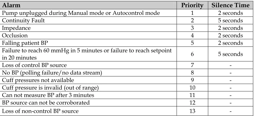
patient. Higher level alarms indicate that the patient is in peril. Table 3.1 indicates the priority
levels for all possible alarm conditions:
Alarm Priority Silence Time
Pump unplugged during Manual mode or Autocontrol mode 1 2 seconds
Continuity Fault 2 5 seconds
Impedance 3 2 seconds
Occlusion 4 2 seconds
Falling patient BP 5 2 seconds
Failure to reach 60 mmHg in 5 minutes or failure to reach setpoint
in 20 minutes 6 5 seconds
Loss of control BP source 7 -
No BP (polling failure/no data stream) 8 -
Cuff pressures not available 9 -
Cuff pressure is invalid (out of range) 10 -
Can not measure BP after 3 minutes 11 -
BP source can not be corroborated 12 -
Loss of non-control BP source 13 -
3.6
Hazard Analysis
The CARA system will be ultimately fielded on up to 3 platforms: LSTAT, DataPak and WPSM
(Hosts). The software will have to accommodate various blood pressure inputs (e.g. arterial line,
non-invasive cuff, pulse wave, etc). The design of the CARA system is generic in form to
accommodate the different architectures that it will ultimately be used on. As a result, a true
hazard analysis is difficult to accomplish in generic terms. Until the system is actually tested on
one of the above systems, the hazard analysis will take the approach of using the Usage Test
Boundary for the CARA as the platform of choice.
The intent of the hazard analysis is to determine what hazards may be present in the CARA
system to the patient, caregiver, and any bystanders. This will be an initial analysis that will
need to be refined as the project develops to a point where the CARA is actually implemented
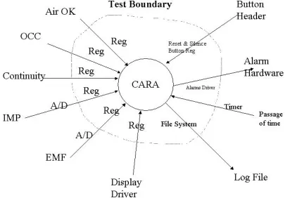
and tested on one of the above platforms. The Test Boundary is defined as shown in Figure 3.3.
The main areas of the hazard analysis will concentrate on the following hazard areas:
a. Incorrect therapy to the patient
b. Incorrect dosages to the patient
c. Possible harm to caregiver, patient, or bystander by interfacing with the pump
d. Possible harm to caregiver in physical handling of the M100 and PMD
e. Harm to patient via M100 infusion pump
f. Harm to patient via PMD connections
due to the following:
1. Loss of power
2. Complete failure of the CARA due to unknown systems failure, to include
environmental factors such as heat and cold temperatures, Electro magnetic
induction, and others
3. Incorrect therapy due to CARA displaying incorrect information
4. Failure of the CARA to display error messages
5. Failure of the alarm/reset routines
6. Failures of individual Hardware components of the Test Boundary
7. Failure of the M100 infusion pump
8. Failure due to indicators not working correctly
3.7
Benefits of using Mathematical Models for CARA
The advantages conferred by using mathematical models such as Spin and UPPAAL are
effectively those associated with the more rigorous levels of formal methods, namely:
Mathematical models are more precise than an informal description written in natural
language or in quasi-formal notations, such as pseudocode, diagrammatic techniques, and
many Computer Aided Software Engineering (CASE) notations. One aspect of precision is
models also tend to force a more thorough analysis. In the case of CARA, it enables us to
model temporal constraints and concurrent operation of the various sub-systems using
UPPAAL and Spin respectively.
Mathematical models can be used to calculate and predict the behavior of the system or
phenomenon modeled. This helps us carry out realistic simulations of CARA in Spin and
UPPAAL.
Mathematical models can be analyzed using established methods of mathematical reasoning.
The axiomatic method that provides a discipline for proving properties and for deriving and
predicting new behaviors from those already known is an example of one such method, in
this case drawn from mathematical logic. Both Spin and UPPAAL allow for verification
based on LTL formulae.
Chapter 4. The UPPAAL Model
4.1
The UPPAAL Model Checker
UPPAAL is a tool box for modeling, simulation and verification of real-time systems, based on
constraint-solving, and on-the-fly techniques, developed jointly by the Design and Analysis of
Real-Time Systems group at Uppsala University, Sweden and Basic Research in Computer
Science at Aalborg University, Denmark.
4.1.1 Introduction.
UPPAAL offers an integrated tool environment for verifying (via automatic model-checking) and
validating (via graphical simulation) real-time systems modeled as networks of timed automata,
extended with data types (bounded integers, arrays, etc.). It consists of two main parts: a
graphical user interface and a model-checker engine. The idea here is to model a system using
timed-automata, simulate it and then verify properties on it. Transitions between states of the
timed automata define how the system behaves. The simulation step consists of interactively
running the system to check that it works as intended. We can then use the verifier to check
reachability properties, with the help of LTL formulae. The model checking is basically an
exhaustive search that covers all possible dynamic behaviors of the system. More precisely, the
engine uses on-the-fly verification combined with a symbolic technique reducing the verification
problem to that of solving simple constraint systems [37, 27]. To facilitate modeling and
debugging, the UPPAAL model-checker automatically generates a diagnostic trace that explains
why a property is (or is not) satisfied by a system description. The diagnostic traces generated by
4.1.2 An overview of UPPAAL.
UPPAAL consists of three main parts: a description language, a simulator and a model-checker.
The description language is a non-deterministic guarded command language with data types
[28]. It serves as a modeling or design language to describe system behavior as networks of
timed automata extended with data variables. The simulator and the model-checker are designed
for interactive and automated analysis of system behavior by manipulating and solving
constraints that represent the state-space of a system description. The simulator enables
examination of possible dynamic executions of a system during early modeling (or design) stages
and thus provides an inexpensive mean of fault detection prior to verification by the
model-checker, which covers the exhaustive dynamic behavior of the system.
The UPPAAL user-interface is built as a client/server architecture, with UPPAAL 's engine as the
server and the GUI as the client. Figure 4.1 shows an outline of the UPPAAL2k model.
The heart of the server, which includes the syntax and the model checker, is a single stepper,
which allows stepping through the reachability graph of a system [5]. The single stepper is
heavily used by the GUI's simulator. The model-checker is designed to check for invariant and
reachability properties, in particular whether certain combinations of control-nodes and
constraints on clocks and integer variables are reachable from an initial configuration. Other
the context of testing automata or simply decorating the system description with debugging
information and then checking reachability properties. The simulator allows the user to examine
the dynamic behavior of a system in an interactive and graphical fashion. In contrast to the
model-checker, which explores the whole reachable state-space of a system - examining all the
behavior of the system, the simulator explores only a particular execution trace i.e. a sequence of
states of the system. This provides an inexpensive mean of fault detection in early stages of
modeling (or design). In comparison, the model-checker is obviously more expensive (in terms
of memory and time requirements) as it amounts to an exhaustive simulation covering all
behavior of the system. Another useful application of the simulator is to visualize a diagnostic
trace generated by the model-checker; thus the user can in an interactive and graphical fashion
examine the execution trace that may result in a system error.
4.1.3 The Description of Models in UPPAAL.
To facilitate modeling, UPPAAL provides both graphical and textual formats for the description
language. One can use either the textual format or the java-based graphical user interface [5] to
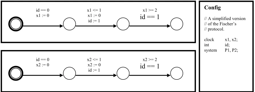
define system descriptions, namely networks of timed automata. As an example, Figure 4.2 gives
the graphical description of a model for the Fischers Mutual Exclusion Protocol [4]. Figure 4.3
gives a corresponding textual description for the same. The textual format provides a basic
programming language for timed automata.
Figure 4.2. Graphical Description of the Fischers Mutual Exclusion Protocol
Config
// A simplified version // of the Fischer’s // protocol.
clock x1, x2;
int id;
system P1, P2; id == 0
x1 := 0
x1 <= 1 x1 := 0 id := 1
x1 >= 2
id == 1
id == 0 x2 := 0
x2 <= 1 x2 := 0 id := 1
x2 >= 2
4.1.3.1. Syntax
The basis of the UPPAAL model is the notion of timed automata [1], developed by Alur and Dill
as an extension of classical finite-state automata with clock variables. To provide a more
expressive model and to ease the modeling task, the timed automata is further extended with
more general types of data variables such as boolean and integer variables. Each transition in
this extended automaton would be given as δ (l, g, a, φ) → l’, where g is a simple linear constraint
over the clock variables and φ is a set of clocks to be reset to zero. δ (l, g, a, φ) → l’ can be
interpreted as “The process in control node l may perform a transition to the control node l’ if the clock constraint g (also called the enabling condition for the transition) is satisfied, thereby
performing the label a, and resetting the clocks in φ.”[27]. The constraint g is called a guard. UPPAAL allows a more general form of guard that can also be a constraint over data variables,
and extends the reset-operation on clocks in timed automata to data variables.
Figure 4.3. Textual Description of the Fischers Mutual Exclusion Protocol
//
// Declarations //
clock x1, x2; int id;
//
// Processes //
process P1 {
state a, b, c, cs;
init a;
trans a -> b {
guard id == 0; assign x1 := 0; },
b -> c {
guard x1 <= 1;
assign x1 := 0, id := 1; },
c -> cs {
guard x1 >= 2, id == 1; };
}
//
// System Configuration //
system P1,P2;
//
// System Configuration //
system P1,P2;
process P2 {
state cs,c,b,a; init a; trans c -> cs {
guard x2 >= 2, id == 2; },
b -> c {
guard x2 <= 1; assign x2 := 0, id := 2; },
a -> b {
guard id == 0; assign x2 := 0; };
4.1.3.2 Guards over Clock and Data Variables.
A guard can be defined as a conjunction of timing and data constraints; a timing constraint is of
the form: x ~ n or x - y ~ n, where n is a natural number and ~ ∈ {<=, >=, =, >, <}. A data
constraint is of a similar form i ~ j or i – j ~ k but with k being an arbitrary integer. The default
guard of an edge is True.
4.1.3.3 Reset-Operations.
When making a transition, clock and data variables may be subject to simple manipulations in
terms of resets being assignments of the form w := e, where w is a clock or data variable and e is
an expression. Up until version 3.0, reset-operations on clock variables were restricted to the
simple form x := n, where n is a natural number, and reset-operations on integer variables were
in the form i := c * I + c’, where c; c’ are integer constants (note that c; c’ may be zero or negative).
These were extended to include decimals in version 3.1.
4.1.3.4 Synchronization using Channels
Automata in a UPPAAL model may communicate either via integer variables (which in UPPAAL
are global) or using communication channels. As in Spin, communication on channels occurs as
two-process synchronizations. To denote the actions that processes can perform when
synchronizing with each other we use the notation a! and a? (denoting the complementary
actions of sending and receiving on channel a). To prevent a network from delaying in a
situation where two components are already able to synchronize, a channel may be declared as
being urgent. For efficiency reasons, edges labeled with synchronization actions on urgent
4.1.3.5 Semantics
Formally, states of a UPPAAL model are of the form (l, v), where l is a control vector indicating
the current control node for each component of the network and v is an assignment given the
current value for each clock and integer variable. A model in UPPAAL determines the following
two types of transitions between states [28]:
Delay transitions. As long as none of the invariants of the control nodes in the current state are
violated, time may progress without affecting the control node vector and with all clock values
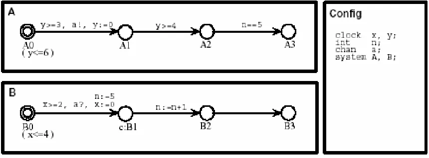
incremented with the elapsed duration of time. Thus, in Figure 4.4, from the initial state ((A0, B0);
x = 0, y = 0, n = 0) time may elapse 3.5 time units, leading to the state ((A0, B0); x = 3.5, y = 3.5,
n = 0). However, time cannot elapse for 5 time units, as this would violate the invariant of B0.
Action transitions. If two complementary labeled edges of two different components are
enabled in a state then they can synchronize. Thus in state ((A0, B0); x = 3.5, y = 3.5, n = 0), the two
components can synchronize on a leading to the new state ((A1, B1); x = 0, y = 0, n = 5) (note that
x, y, n have been appropriately updated). If a component has an internal edge enabled, the edge
can be taken without any synchronization. Thus in state ((A1, B1); x = 0, y = 0, n = 5), the
B-component can perform without synchronizing with A, leading to the state ((A1, B2); x = 0, y = 0,
n = 6).
The above two types of transitions may be overruled by presence of urgent channels and
committed locations in the following ways:
Urgent Channels. In a state where two components may synchronize on an urgent channel no
further delay is allowed. Thus, in Figure 4.4, if channel a is urgent, time may not elapse 3.5 units
from the initial state ((A0, B0); x = 0, y = 0, n = 0) as synchronization on a is already possible in the
state ((A0, B0); x = 3, y = 3, n = 0).
Committed Locations. If in a state, one of the components is in a control node labeled as being
committed, no delay is allowed to occur and any action transition (synchronization or not) must
involve the particular component (the component is so-to-speak committed to continue). In the
state ((A1, B1); x = 0, y = 0, n = 5), B1 is committed; thus without any delay the next transition must
involve the B-component; i.e. the next state of the network is ((A1, B2); x = 0, y = 0, n = 6). Hence
the two first transitions of B are guaranteed to be performed atomically.
4.1.3.6 Model Checking
The model-checking procedure implemented in UPPAAL is based on an interpretation using a
finite-state symbolic semantics of networks. The logic is interpreted with respect to symbolic
states of the form (l, D), where D is a constraint system (i.e. a conjunction of atomic clock and data
constraints) and l a control vector. Thus, a symbolic state (l, D) represents all the states (l, v)
where v satisfies the constraint D. Based on this notion of symbolic state, the heart of the
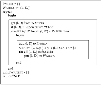
UPPAAL model-checking procedure is the abstract reachability algorithm shown in Figure 4.5,
which reduces the reachability problem to that of solving simple constraint systems. The
algorithm is to check whether a timed automaton may reach a state satisfying a given state
The algorithm depends heavily on the test operations for checking the inclusion D ⊆ D’ (i.e. the
inclusion between constraints D and D’) and the emptiness of Ds in constructing the successor set
SUCC of (l, D). Clearly, it is important to design efficient data structures and algorithms for the
representation and manipulation of clock constraints. UPPAAL uses one such data structure,
known as Difference Bounded Matrices [16], DBM, which offers a canonical representation for
constraint systems. A DBM representation is a weighted directed graph where the vertices
correspond to clocks (including a zero-clock) and the weights on the edges stand for the bounds
on the differences between pairs of clocks.
In UPPAAL, the implementation the reachability algorithm of Figure 4.5 is extended so that a
diagnostic trace is automatically generated as a side-effect in case reachability is established. If Figure 4.5. The algorithm for Symbolic Reachability Analysis
PASSED := { }
WAITING := {(l0, D0)} repeat
begin
end
until WAITING = { } return “NO”
get (l, D) from WAITING
if (l, D) |=βthen return “YES”
else if D
⊄
D’ for all (l, D’) ∈ PASSED then beginend
add (l, D) to PASSED
SUCC := {(ls, Ds): (l, D) → (ls, Ds)
∧
Ds≠ φ
} for all (ls, Ds) in SUCC dothe symbolic state-space is examined in a breadth-first manner (corresponding to organizing the
waiting set as a queue), the trace is guaranteed to be the shortest possible.
4.1.4 Optimizations
As DBM gives an explicit bound for the difference between each pair of clocks, its space-usage is
in the order of O(n2), where n is the number of clocks. However, in practice it often turns out that
most of these bounds are redundant. UPPAAL employs three different optimization techniques
for space and time savings:
1. by providing a new compact data structure for DBM, which provides minimal and canonical
representations of clock constraints with a minimization of the weighted directed graph
representing the constraint system,
2. by using a global reduction technique to reduce the total number of symbolic states to save in
the global data structure, i.e. the passed list, and
3. by saving the symbolic state-space generated during checking of a property and re-using it in
the checking of other properties. In cases where several correctness properties have to be
examined this leads to significant time savings.
4.2
Modeling CARA Using UPPAAL
The CARA was modeled in UPPAAL with the help of processes emulating the behavior of
system components. The processes all use clocks (clock variables) that are local to them, but are
synchronized with each other. Channels are used to communicate between processes. Loosely,
the processes can be categorized as
a. System Processes, which are used to define the operation of each unit in the system. These
b. Observers, which are add-on automata in charge of detecting events without perturbing the
observed system. In our model, Observers are used to modify certain global variables and
study their effect on the system during simulation.
A brief description of these processes follows.
4.2.1 The CARA Process.
The CARA process is designed as an elaborate automaton with various locations representing
possible states that the system may exist in at any given time. Transitions between states are
modeled based upon the values of global variables corresponding to the mode, the BP source,
cuff readings, etc. and the current clock readings. Channels are used to issue alarms, in case such
an error is detected, and also to synchronize with other processes. The locations are constantly
checked for any indication of errors or missed readings that may cause an alarm. Since multiple
synchronizations are not allowed in UPPAAL, committed locations are used to simulate actions
that are performed simultaneously.
4.2.2 The Pump Process.
The Pump process is used to generate readings (cuff and beat-to-beat) based on the mode and
blood pressure source values. The process lies dormant till it receives a message to generate a
cuff reading (indicating that the system is in Autocontrol mode and that the cuff pressures are
inflated). Upon receiving this message, the process generates a blood pressure reading
non-deterministically. It then continues in a loop, checking for the blood pressure source and
producing cuff pressure or beat-to-beat readings correspondingly. At any instant if the system
reverts to Manual mode, the process breaks out of the loop and waits for the next request for a
4.2.3 The Alarm Process.
The alarm process simulates the possible alarm conditions that may arise during the operation of
the CARA system, as given in Table 2.1. A distinction is made between level 1 and level 2 alarms;
moreover, each alarm condition is associated with a certain priority. The lowest priority is used
to indicate that none of the other conditions hold true, and corresponds to a ‘No alarm’ state. The
process also incorporates the silence and reset buttons with a silence-time corresponding to each
of the alarm conditions. On receiving a ‘silence’ signal, the alarm is disabled for the duration given by the silence-time, to allow for the bug to be fixed. On receiving a reset signal, all alarms
are flushed and the alarm is set to the lowest priority.
4.2.4 The Observers.
The Observers in the CARA model include the processes Medic, Patient, CheckPump, and
CheckEMF. The Medic process mimics the role of a medic controlling the functioning of the
CARA system. This consists of sending messages to start and terminate Autocontrol mode
(based on the current mode and the status of the pump and the Host) and to decide whether or
not to override a non-corroborated blood pressure source.
The Patient process simply makes a transition on each reading, updating the flow rate and the
average blood pressure in the process.
The CheckPump and CheckEMF observers emulate the polling process in the CARA system.
Both processes maintain a set of variables to indicate the status of the system. These variables
corresponding to the back-EMF, impedance, connections, airlock and occlusion are
non-deterministically assigned truth-values in the course of the various transitions. The variables, in
turn trigger the various error signals that are sent to the Alarm process.
4.3
Simulation Using UPPAAL
The CARA model described above can be simulated using the UPPAAL Simulator. An instance
is created for each process defined, and declared in the System definition. The Simulator
produces an execution trace for each instance of the processes defined, maintaining a set of
variables as it goes along. The Simulator also allows a trace file to be maintained containing a list
of all the transitions made, and allows for either a manual selection of the transitions or a random
set of transitions (with variable speed) while producing the execution trace. Simulation of the
CARA model ascertains proper execution of the processes, and provides an effective means of
studying and debugging the model. The simulation is used to ensure the following.
All states of the automata network are reached.
Average Blood pressure and flow rates are in conformance with expected values.
No deadlocks are detected during the execution.
Proper synchronization occurs between the different processes.
Alarms are generated at the correct times and have the correct priority and silence times.
A screen shot of the UPPAAL Simulator is given in Appendix D, depicting the execution trace of
the CARA model.
4.4
Verification Using UPPAAL
UPPAAL does not provide an exhaustive state search, or a protocol analyzer like Spin, however it
does provide a query analyzer. Thus, the verification of the CARA model is carried out with the
help of linear temporal logic (LTL) formulae. Specifications of the CARA system (as given by the
requirement documents) are translated into LTL formulae in the form of queries, and
subsequently verified for correctness using the UPPAAL Query Analyzer. A list of these queries
Chapter 5. The Spin Model
5.1
The Spin Model Checker
Spin is a generic verification system that supports the design and verification of asynchronous
process systems [22, 24]. Spin verification models are focused on proving the correctness of
process interactions, and they attempt to abstract as much as possible from internal sequential
computations. Process interactions can be specified in Spin with rendezvous primitives, with
asynchronous message passing through buffered channels, through access to shared variables, or
with any combination of these. Spin accepts design specifications written in the verification
language Promela (a Process Meta Language), and it accepts correctness claims specified in the
syntax of standard Linear Temporal Logic. The description of a concurrent system in Promela
consists of one or more user-defined process templates, or proctype definitions, and at least one
process instantiation. The templates define the behavior of different types of processes. Any
running process can instantiate further asynchronous processes, using the process templates.
The basic structure of the Spin model checker is illustrated in Figure 5.1. The typical mode of
working is to start with the specification of a high level model of a concurrent system, or
distributed algorithm, typically using Spin’s graphical front-end XSpin. After fixing syntax
errors, interactive simulation is performed until basic confidence is gained that the design
behaves as intended. Then, in a third step, Spin is used to generate an optimized on-the-fly
verification program from the high level specification. This verifier is compiled, with possible
compile-time choices for the types of reduction algorithms to be used, and executed. If any
counterexamples to the correctness claims are detected, these can be fed back into the interactive
5.1.1 Operation
Spin translates each process template into a finite automaton. The global behavior of the
concurrent system is obtained by computing an asynchronous interleaving product of automata,
one automaton per asynchronous process behavior. The resulting global system behavior is itself
again represented by an automaton. This interleaving product is often referred to as the state
space of the system, and, because it can easily be represented as a graph, it is also commonly
referred to as the global reachability graph.
To perform verification, Spin takes a correctness claim that is specified as a temporal logic
formula, converts that formula into a Büchi automaton, and computes the synchronous product
of this claim and the automaton representing the global state space. The result is again a Büchi
automaton. If the language accepted by this automaton is empty, the original claim is not
satisfied for the given system. If the language is nonempty, it contains precisely those behaviors
that satisfy the original temporal logic formula. Spin uses the correctness claims (and temporal
logic formulae) to formalize systems erroneous system behaviors, i.e., behaviors that are
undesirable. The verification process then either proves that such behaviors are impossible or it
provides detailed examples of behaviors that match.
In the worst case, the global reachability graph has the size of the Cartesian product of all
component systems. The specification language Promela is defined in such a way that each
component always has a strictly finite range. This applies to processes (which can have only
finitely many control states), but also to all local and global variables (which can have only
finitely many distinct values), and all message channels (each with bounded and user-defined
capacity).
The entire computation, starting from the individual concurrent components and a single Büchi
automaton representing the correctness claim, is done by Spin in one single procedure, using a
nested depth-first search algorithm [15]. The algorithm terminates when an acceptance cycle is
found (which then constitutes a counterexample to a correctness requirement), or, when no
counterexample exists, when the complete intersection product has been computed.
5.1.2 The Nested Depth-First Search Algorithm
A Büchi automaton accepts a system execution if and only if that execution forces it to pass
through one or more of its accepting states infinitely often. We call such behaviors acceptance
detection method used in Spin is of central importance as it must be compatible with all modes of
verification, including exhaustive search, bit-state hashing, and partial order reduction
techniques.
The principle of the nested depth-first search algorithm is as follows. For an accepting cycle to
exist in the reachability graph at least one accepting state must be both reachable from the initial
system state (the root of the graph) and it must be reachable from itself. The first depth-first
search establishes which accepting states are reachable from the initial system state. The second
(nested) search starts at each accepting state thus detected, and it checks whether or not that state
is reachable from itself. If it is, a complete execution sequence that includes the acceptance cycle
has also been constructed: it is the concatenation of all the steps that are on both the first and the
second depth-first search stack. In the context of the Spin model checker, this execution sequence
always equates to a counterexample of a user-defined correctness claim, and it can be printed as
proof that the correctness claim is invalid for the system as specified.
The nested depth-first search algorithm does not preserve the capability to detect all possible
acceptance cycles that may appear in the reachability graph. It can, however, be proven to detect
at least one such cycle if one or more cycles exists [23, 15]. Since acceptance cycles in Spin
constitute counterexamples to correctness claims, establishing either their absence or their
presence always suffices for the purposes of verification.
The nested depth first search algorithm in Spin is extended with an optional weak fairness
constraint, using Choueka’s flag construction method [15]. Under the weak fairness constraint,
every process that contains at least one transition that remains enabled infinitely long is