Fast Detection Of Short Circuit Current In Pv Distributed Generator
With Incremental Conductance Technique
1
D. Chandrashekar, 2B.Saritha, 3K.Srinivas 1
assistant Professor, Vignanabharathi Engineering College
2
assistant Professor, Vignanabharathi Engineering College
3
assistant Professor, Thirumala Engineering College
ABSTRACT- In this paper, the PV-STATCOM is used to stabilize a critical induction motor load in the vicinity of the solar farm, which would have otherwise become unstable due to the grid fault. A new fast technique in which the slope of a PV inverter current is utilized to predict if the current is expected to exceed its rated value due to any grid faults is proposed in this paper. The objective was to prevent the loss of opportunity to integrate more PV based renewable generation. In this paper we use the IC technique, it is used to track the maximum power point of the PV source. In incremental conductance method the array terminal voltage is always adjusted according to the MPP voltage it is based on the incremental and instantaneous conductance of the PV module. Two applications of this technique are demonstrated. In jurisdictions where grid codes require DGs to disconnect after a fault occurrence, such as in Ontario, Canada, this technique is utilized to rapidly disconnect the PV solar system even before the inverter short circuit current actually exceeds the rated current of the inverter thereby obviating the problem of any adverse short circuit current contribution into the grid. By using the simulation results we can demonstrate the effectiveness of this technique with incremental conductance algorithm .
Index Terms— Photovoltaic (PV) systems, Distributed Generator (DG), Inverter, Short Circuit Current, Protection, STATCOM, IC technique, PV-STATCOM, Flexible AC Transmission System (FACTS)
INTRODUCTION
The short circuit current detection technique proposed in this paper can be utilized to shut down the real power generating function of the PV solar farm very rapidly in the event of a fault, and autonomously transform the PV solar farm into a STATCOM (PV-STATCOM) with full inverter capacity.
In electric power systems, integration of more Distribute Generators (DGs) in the network increases the short circuit level due to the short circuit current contribution of the DG during faults [1]. Compared to the synchronous an induction machine based generators the inverter base generators, such as Photovoltaic (PV) solar system contribute lower fault current to the network due to the characteristics of PV panels and inverter operation. The short circuit current contribution from a PV system inverter typically in the range of 1.2 times rated current for the large size inverter (1MW), 1.5 times (500kW) for medium size inverter and between 2 - 3 times for smaller inverters. Although, each PV solar farm may contribute short circuit
contribution may become unacceptably large for a feeder which has several PV systems connected.
The objective was to prevent the loss of opportunity to integrate more PV based renewable generation in the Ontario distribution systems. It is important to note that in Ontario, and in some other jurisdictions in Canada, it is required to disconnect the PV solar farms or any other DGs upon detection of fault on the system. It is therefore important to detect the faults rapidly, and either disconnect the DGs from the network or provide grid support functions e.g. LVRT, as quickly as possible, depending upon the prevalent grid code requirements.
As a first step, adequate modeling of PV solar plants for predicting their short circuit contributions during network faults. Continuous Wavelet Transform (CWT) has been used to process voltage and current transients for calculating the change in supply impedance. A four-stage fault protection scheme against short-circuit fault for inverter based DGs is proposed in [18]. The inverter is initially controlled as a voltage source, which changes to the current controlled mode upon detection of the fault, thereby limiting the inverter output current.
To prevent any short circuit current contribution these techniques have not been used in excess of the rated or utility-acceptable current output of PV solar inverters. This paper presents a new fast short circuit current detection technique based on the rate of rise of current together with the current magnitude in a PV solar system based DG, deriving its concepts from the patent [25]. The short circuit current is detected very rapidly and any of the following two control operations can be initiated, per the applicable grid code in that region: i) disconnect the PV inverter before the current exceeds the rated output current of the inverter.
It is emphasized that the objective of the proposed technique is not to detect the occurrence of any fault in the network but only to identify such fault conditions during which the inverter short circuit current is likely to exceed its rated magnitude.
provide grid support functions. In this paper a case study is presented when a fault in the network causes a critical inductor motor load to get destabilized. The proposed technique does not disconnect the PV inverter. Instead it transforms autonomously and rapidly the PV solar inverter into a STATCOM and helps stabilize this critical induction motor load. An initial study on non-autonomous stabilization of induction motors using the concepts of the PVSTATCOM technology was discussed in [32].
SYSTEM MODEL
The study system is comprised of a typical realistic distribution network with a PV solar farm [33] as shown in Fig. 1.
Fig. 1. One line diagram of the study system. A total distributed load of 15 MVA is modeled as three groups of fixed impedance three phase static loads connected to the feeder and a large load at the end of the feeder. The adjacent feeder load of 60MW at 0.9 pf. is modeled as a single aggregated P-Q load connected at the beginning of the feeder.
A 7.5MW PV solar farm is connected near the end of the feeder.
B.PV System Model
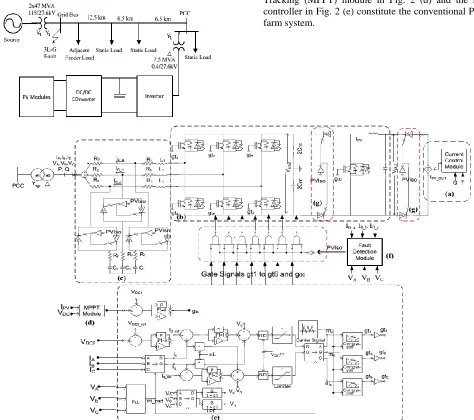
Fig. 2 presents the detailed PV system model. The PVmodule in Fig. 2 (a), boost converter and inverter in Fig. 2 (b), AC filter in Fig. 2 (c), Maximum Power Point Tracking (MPPT) module in Fig. 2 (d) and the inverter controller in Fig. 2 (e) constitute the conventional PV solar farm system.
The PV module is modeled as DC voltage controlled DC current source [35]. The boost converter and inverter along with its controller is used to transfer all the available power to the AC grid by regulating the DC voltage across the DC link capacitor with the use of DC link reference obtained from MPPT module. The boost converter [36] performs the MPPT and inverter regulates DC link voltage. The inverter maintains unity power factor operation by regulating reactive power output to zero.
The proposed fault detection module is shown in Fig. 2(f), and the internal circuit diagram of it is described in Fig 3.
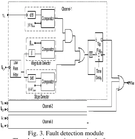
Fig. 3. Fault detection module
The slope detector is comprised of a comparator which compares the derivative of PCC current to determine the slope and compares with a reference slope (d/dt)max. For an inverter current i = I msinωt, the reference slope or threshold limit can be determined approximately with the magnitude of (d/dt) of rated current as shown in the following expression [20].
𝑑𝑖/𝑑𝑡 ≈ 𝑘𝜔𝐼𝑛 (1)
where, Im is the peak magnitude of instantaneous inverter current, k is an arbitrarily selected tolerance constant (typically chosen to be 1.0 - 1.06) based on the maximum inverter current injection considered acceptable by the utility during normal operating conditions, and ɷ is the fundamental angular frequency.
In order to eliminate an unnecessary tripping of the inverters, the rate of change of voltage at inverter terminal is monitored. During a fault, the rate of change of voltage is higher compared to that during a large-load switching. The PV Iso signal is used to isolate the PV panel from the grid by using fast solid state switch as shown in Fig 2(g). As a result, the PV solar inverter stops the power
hundred micro-seconds upon detection of any symmetrical or unsymmetrical fault in the grid.
CASE STUDIES
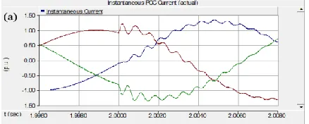
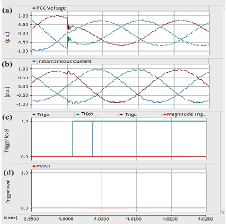
Case studies are performed on the 7.5 MW PV solar system model as shown in Fig. 1 by applying different types of faults at PCC with proposed fault current controller enabled. The base value of a PV inverter current at PCC is 0.25 kA. Triga, Trigb, and Trigc are the outputs of slope detector from the proposed controller for phase A, B and C, respectively.
Similarly, Magnitude Trigger is the resultant output of magnitude detector for all the three phases. PV Iso is the triggering signal provided by the fault current controller. These conventions hold true for all PSCAD studies. The simulation results obtained from PSCAD are described below.
INCREMENTAL CONDUCTANCE MPPT
In incremental conductance method the array terminal voltage is always adjusted according to the MPP voltage it is based on the incremental and instantaneous conductance of the PV module.
Fig.4: Basic idea of incremental conductance method on a P-V Curve of solar module
Fig-9 shows that the slope of the P-V array power curve is zero at The MPP, increasing on the left of the MPP and decreasing on the Right hand side of the MPP. The basic equations of this method are as follows.
𝑑𝑙 𝑑𝑣 = −
1
𝑣 𝐴𝑡 𝑀𝑃𝑃 𝑑𝑙
𝑑𝑣 > − 1
𝑣 𝐿𝑒𝑓𝑡 𝑜𝑓 𝑀𝑃𝑃 𝑑𝑙
𝑑𝑣 < − 1
𝑣 𝑟𝑖𝑔𝑡 𝑜𝑓 𝑀𝑃𝑃 (2)
Where I and V are P-V array output current and voltage respectively. The left hand side of equations represents incremental conductance of P-V module and the right hand side represents the instantaneous conductance. When the ratio of change in output conductance is equal to the negative output conductance, the solar array will operate at the maximum power point.
This method exploits the assumption of the ratio of change in output conductance is equal to the negative output Conductance Instantaneous conductance. We have,
𝑃 = 𝑉𝐼 (3) Applying the chain rule for the derivative of
𝜕𝑃
𝜕𝑉= 𝜕 𝑉𝐼 𝜕𝑉 𝜕𝑃
𝜕𝑉= 0 (4)
The above equation could be written in terms of array voltage V and array current I as
∂I/∂V = - I/V (5)
The MPPT regulates the PWM control signal of the dc – to – dc boost converter until the condition: (∂I/∂V) + (I/V) = 0 is satisfied.
In this method the peak power of the module lies at above 98% of its incremental conductance. The Flow chart of incremental conductance MPPT is shown below.
Fig.5. Flowchart for IC MPPT of switched PV approach.
A. Symmetrical Fault
Fig. 4(a) demonstrates that the magnitude of inverter output current at PCC during line-to-line-to-line-to-ground (LLLG) fault at t = 2 second increases from 1 p.u. to 1.45 p.u.
Fig. 6. (a) Inverter fault current at PCC during LLLG fault at t = 2 second
It is noticed from Fig. 6(b) that 'Trigc' signal becomes high within 0.3 ms from the initiation of fault in the grid, as slope of phase C (di/dt) has violated its permissible limit. Subsequently, Trigb and other triggering signals also get high.
Fig. 6. (b) Triggering signals
However, the notable feature of the fault current controller is that only one triggering signal is needed to disconnect the PV inverter from the grid.
Fig. 6. (c) Inverter fault current with proposed fault controller
Fig. 6(c) portrays the inverter current with the proposed fault detector module activated.
B. Asymmetrical Fault
Fig. 7(a) depicts the inverter current after the occurrence of a single line-to-ground (SLG) fault at t = 2 second. The magnitude of inverter output current at PCC rises to 1.3 p.u.
Fig. 7. (a) Inverter fault current at PCC during SLG fault at t =2 second
Fig. 7. (b) Triggering signals
As soon as the 'Trigb' signal becomes high, inverter fault current at PCC starts decreasing as shown in Fig. 7(c).
Fig. 7. (c) Inverter fault current with proposed fault controller
C. Different Faults at Different Time Instants
Fault studies are performed by applying different types of faults at different time instants and it is confirmed that the controller responds in the expected manner regardless of any type of fault at any time instant.
Fig.8(a) depicts that the magnitude of inverter output current at PCC increases from 1 p.u. to 1.45 p.u. during line to-line ground fault at t = 4.5 second.
Fig. 6. (a) Inverter fault current at PCC during LLG fault at t = 4.5 second
Fig. 8. (b) Triggering signals
Inverter fault current at PCC starts decreasing immediately upon detection of fault as shown in Fig. 8(c).
Fig. 8. (c) Inverter fault current with proposed fault controller
Therefore, there is no apprehension of any adverse short circuit current contribution from the PV inverter.
D. Load Switching
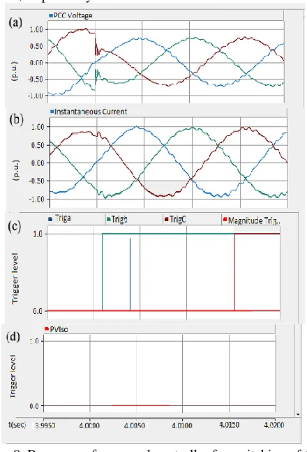
The performance of the controller is tested for two large load switching scenarios. Figs. 9 and 10 depict the inverter output and fault current detector signals for switching of 60 MVA static load and 25 MVA induction motor, respectively.
Fig. 9. Response of proposed controller for switching of 60 MVA static load at feeder end
Fig. 10. Response of proposed controller for switching of 25 MVA induction motor load at feeder end.
The controller is also tested for its performance during the reclosure operation of a relay. Fig. 11 illustrates the inverter output and fault current controller response for fast reclosure operation of the relay.
Fig. 11. Response of proposed controller for fast reclosure operation of relay.
Fig. 11 illustrates the inverter output and fault current controller response for fast reclosure operation of the relay. But similar to load switching, the rate of change of voltage is less than the reference value and thus the overall fault detector does not generate any tripping signal. This demonstrates that the short circuit current controller can successfully discriminate between a fault and other transient high current events. The above studies illustrate that in regions where the grid codes do not require LVRT, and require DG inverters to shut down following a fault, the proposed predictive technique shuts off the PV inverter rapidly without allowing the short circuit current to exceed the rated current of the inverter.
GRID VOLTAGE SUPPORT DURING FAULT
The application of the proposed short circuit current detector for providing rapid reactive power support to stabilize a critical induction motor. This application is especially relevant in jurisdictions where the grid codes require LVRT capability or a grid support function from DG inverters during faults.
As the IM is rated for lower voltage, a step down transformer (not shown in the one line diagram) is used to match the IM voltage ratings. The PV solar farm is connected at an intermediate location in the feeder, away from the induction motor.
Fig. 10. Study System for PV solar farm operation as STATCOM for stabilizing critical induction motor load.
The PV-STATCOM controller is described. Due to space reasons the detailed description of the PV- STATCOM controller is not provided here, only its application in stabilizing the critical induction motor is presented. A three phase to ground fault for 9 cycles is initiated at the motor terminals in this case study.
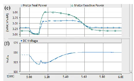
A.Case 1: Conventional PV System Disconnected During Fault
DC power and real and reactive power generation by the PV solar farm are demonstrated in Fig. 13(c), the real and reactive power drawn by the IM are presented in Fig. 13(d), and DC link voltage is depicted in Fig.13(e).
Fig. 13. Behaviour of Induction Motor Load after grid fault.
B. Case 2: PV System Operation as PV-STATCOM
Fig. 14 illustrates the IM response when the proposed short circuit current detector rapidly detects the fault and transforms the PV solar farm into a PV-STATCOM in PCC Voltage control mode of operation.
Fig. 14. Behaviour of Induction Motor with PV solar farm transformed into PV-STATCOM by the proposed short
circuit current detector
The PV STATCOM immediately starts producing reactive power and provides voltage support to the grid thereby stabilizing the critical induction motor. The reactive power of the PV STATCOM eventually goes to zero after some time (which is not shown in the figure). The solar farm can autonomously transform back from PV-STATCOM mode to normal PV solar power generation mode after the motor is stabilized (although not demonstrated in this paper due to space limitation).
CONCLUSION
In this paper, a novel fast short circuit current detection technique is proposed for PV inverter based DGs. In incremental conductance method the array terminal voltage is always adjusted according to the MPP voltage it is based on the incremental and instantaneous conductance of the PV module.The technique can successfully discriminate between faults and large load switching and relay initiated operations. Among all the MPPT strategies, the incremental conductance technique is widely used due to the high tracking accuracy at steady state and good adaptability to the rapidly changing atmospheric conditions. This technique is general and can be applied on a PV solar system connected in any grid network. The objective of this technique is to facilitate PV solar farms in obtaining permission to get connected in substations or feeders which have already reached their short circuit current limits without the apprehension of additional short circuit current contribution from these solar farms. In this paper this fast fault detection technique is utilized to autonomously initiate a new control function of PV solar farm as a STATCOM (PV-STATCOM).
REFERENCES
[1] F. Katiraei, C. Sun and B. Enayati, ―No Inverter Left Behind: Protection, Controls, and Testing for High Penetrations of PV Inverters on Distribution Systems‖, IEEE Power and Energy Magazine, vol. 13, no. 2, pp. 43-49, March-April 2015.
Synchronous Machine and Inverter Based Distributed Generators‖, IEEE Trans. on Power Delivery, Vol. 22, No. 1, Jan. 2007
[3] Mesut E. Baran and Ismail El-Markaby, ―Fault Analysis on Distribution Feeders with Distributed Generators,‖ in IEEE Trans. on Power Systems, vol. 20. no.4, pp. 1757-1764, 2005.
[4] S.M. Brahma and A.A. Girgis ―Development of Adaptive Protection Scheme for Distribution Systems with High Penetration of Distributed Generation,‖ IEEE Trans. on Power Delivery, Vol. 19, No. 1, January 2004.
[5] W. Johnston and F. Katiraei, ―Impact and sensitivity studies of PV inverters contribution to faults based on generic PV inverter models,‖ Ontario Grid Connection Study, May 2, 2012. available
[6] R.J. Bravo, R. Yinger, and S. Robles, "Three phase solar photovoltaic inverter testing", Proc. 2013 IEEE Power and Energy Society General Meeting, pp.1-5, 2013
[7] N. Jenkins, R. Allan, P. Crossley, D. Kirschen, and G. Strbac, Embedded Generation. London: The Institution of Engineering and Technology (IET), 2000.
[8] H. Hooshyar and M. E. Baran, ―Fault analysis on distribution feeders with high penetration of PV systems,‖ IEEE Trans. on Power Systems, vol. 28, no. 3, pp. 2890– 2896, Aug. 2013.
[9] Hydro One Networks Inc, Distributed Generation Technical Interconnection Requirements; Interconnection at Voltages 50kV and Below, Hydro One, Toronto, DT-10-015, rev. 2, June 2011.
[10] BC Hydro Distributed Generation. Technical Interconnection Requirements. 100 kW and Below. (DGTIR-100). Revision 1. October 17, 2014
[11] Canadian Standards Association (CSA) Standard C22.2 No. 107.1-01, General Use of Power Supplies, 2001, reaffirmed 2011.
[12] E.ON Netz grid code—High and extra high voltage,‖ E.ON Netz GmbH. Bayreuth, Germany [13] ENTSO-E Network Code for Requirements for Grid Connection Applicable to all Generators, 8 March 2013;
[14] ―Recommendations for Updating the Technical Requirements for Inverters in Distributed Energy Resources‖, Smart Inverter Working Group Recommendations, California, January 2014
[15] Qianggang Wang, Niancheng Zhou, and Ling Ye, ―Fault Analysis for Distribution Networks With Current-Controlled Three-Phase Inverter Interfaced Distributed Generators‖, IEEE Trans. on Power Delivery, vol. 30, no. 3, pp1532- 1542, Jun 2015