Available online: https://edupediapublications.org/journals/index.php/IJR/ P a g e | 2256
Flexible Control of Wind Farm Based DSTATCOM Using External
Inductor for Better Performance
Annaldas Saicharan & D. Prasada Rao 1
2Associate professor Department of EM. Tech Student Department of EPSEE ELLENKI College of Engg & Tech ELLENKI College of Engg & Tech
ABSTRACT
Distribution compensator
(DSTATCOM) is utilized for load voltage control and its execution essentially relies on the feeder impedance and its tendency (resistive, inductive, stiff, non-stiff). Be that as it may, a review for examining voltage regulation execution of DSTATCOM relying on system parameters is not all around characterized. This paper expects to give a exhaustive investigation of design, operation, and adaptable control of a DSTATCOM working in voltage control mode. A point by point investigation of the voltage direction capacity of DSTATCOM under different feeder impedances is exhibited. At that point, a benchmark design methodology to figure the estimation of external inductor using advanced controller is exhibited. A dynamic reference regulation voltage era plot is additionally created which enables DSTATCOM to adjust load reactive power amid typical operation, notwithstanding giving voltage bolster amid unsettling influences.
1.INTRODUCTION
Available online: https://edupediapublications.org/journals/index.php/IJR/ P a g e | 2257 for voltage direction consider exceedingly
inductive and additionally altogether vast feeder impedance [11]. This is generally not valid in a dispersion system where feeder impedance used to be resistive in nature. In this situation, the DSTATCOM will have little voltage direction capacity critical issue is the era of reference load voltage. In customary DSTATCOM application for voltage direction, reference regulation voltage is set at 1.0 p.u. At this load voltage, VSI dependably trades receptive power with the source with driving force calculate. This causes constant power misfortunes in the feeder and VSI. Likewise, an ordinary DSTATCOM requires high current rating voltage source inverter (VSI) to give voltage bolster [11]. This high current prerequisite builds the power rating of the VSI and delivers more misfortunes in the switches and in addition in the feeder.
The voltage control execution of DSTATCOM basically relies on the feeder impedance and its tendency (resistive, inductive, stiff, non-stiff). For voltage control mode (VCM) operation of DSTATCOM as well as matrix associated inverters, the thought of embeddings an external inductor in line has been accounted. Be that as it may, in these plans, just the idea has been presented leaving adequate
degree for further examination what's more, understanding into the plan points of interest.
2. DSTATCOM IN POWER DISTRIBUTION SYSTEM
Fig. 1 shows power circuit diagram of the DSTATCOM topology associated in distribution system. Ls and Rs are source inductance and resistance, individually. An external inductance, Lext is incorporated into arrangement amongst load and source focuses.
This inductor causes DSTATCOM to
Available online: https://edupediapublications.org/journals/index.php/IJR/ P a g e | 2258
3. EFFECT OF FEEDER IMPEDANCE ON VOLTAGE REGULATION
To show the impact of feeder impedance on voltage control execution, a proportionate source-regulation show without considering external inductor is appeared in Fig. 2. The current in the circuit is given as
are rms source voltage, rms load voltage, rms source current, feeder impedance, load angle, power factor angle, and feeder impedance angle,
respectively. The three phase average load power (Pl) is expressed as
Pl = Real [3V l _ Is_] : (2)
Substituting V l and Is in (2), the load active power is
For power exchange from source to load with
stable operation in an inductive feeder,
additionally, every one of the terms of the second
piece of (4), i.e., inside cos1, are amplitude and
will positive. Along these lines, estimation of the
second part will be between for the
whole operation of the load l. Therefore, the load
l point will lie between for
the whole operation of the load l. Therefore, the
load l point will lie between under any load l
operation, and in this manner, greatest
conceivable load point is s. The vector expression
for source voltage is given as takes after
Available online: https://edupediapublications.org/journals/index.php/IJR/ P a g e | 2259 DSTATCOM voltage direction capacity at
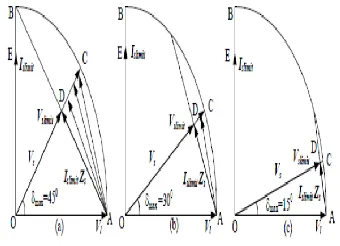
various supply voltages for diverse Rs=Xs, vector design utilizing (5) are attracted Fig. 3. To draw graphs, voltage regulation Vl is taken as reference phasor having the ostensible esteem OA (1.0 p.u.). With point of making Vl = Vs = 1.0 p .u., locus of Vs will be a half circle of range Vl. Since, the greatest conceivable load edge is 90 in an inductive feeder, phasor Vs can be anyplace inside bend OACBO. It can be seen
that the estimation of must be more prominent than 90 for zero voltage control. Furthermore, it is conceivable just when power element is driving at the loadl terminal as s can't be more than 90 Fig. 3(a) demonstrates the
restricting situation when
maximum value of
angle, can be
Hence, the limiting source current phasor OE, which is denoted by Is limit, will lead the load
voltage by Lines OC and AB demonstrate the constraining vectors of Vs and IsZs, separately with D as the crossing point. Subsequently, range under ACDA demonstrates the working district of DSTATCOM for voltage control. The point D has a constraining estimation of Vs limit = Is Zs = 0.706 p .u. In this way, greatest conceivable voltage control is 29.4%. Nonetheless, it is difficult to accomplish
these two breaking points all the while as and - can't be most extreme at a similar time. Again if Zs is low at that point source current, which will be practically inductive, will be sufficient to be acknowledged by a DSTATCOM.
Available online: https://edupediapublications.org/journals/index.php/IJR/ P a g e | 2260 about higher rating of IGBT switches and also
expanded misfortunes. One more point worth to be noted is that, in the resistive feeder, there will be some voltage drop in the line at ostensible source voltage which the DSTATCOM may not be capable compensate to look after load voltage at 1.0 p.u. indeed, even with a perfect VSI..
4. SELECTION OF EXTERNAL INDUCTOR FOR VOLTAGE REGULATION IMPROVEMENT AND RATING REDUCTION
This segment exhibits a summed up system to choose External inductor for development in DSTATCOM voltage control ability while lessening the present rating of VSI. Fig. 4 indicates single stage comparable DSTATCOM circuit design in distribution system. With adjusted voltages, source current will be
feeder resistance and reactance, respectively. Rext is equivalent series resistance (ESR) of external inductor, and will be small. With
as effective impedance angle and effective feeder impedance, respectively, the imaginary component of Is is given as effective impedance angle and effective feeder impedance, respectively, the imaginary component of Is is given as
With the addition of external impedance, the effective feeder impedance becomes predominantly inductive. Hence, Zsef _ Xsef . Therefore, approximated Iims will be
Available online: https://edupediapublications.org/journals/index.php/IJR/ P a g e | 2261
Fig.4. Single phase equivalent circuit of DSTATCOM topology with external inductor in distribution system. Compensator current used for voltage regulation (same as Iims) is obtained by subtracting Iim l from Ivsi and given as follows
Comparing (8) and (10) while using value of _ from (4), following expression is obtained
The above expression is utilized to process the estimation of external inductor. Plan case of
external inductor, utilized for this work, is given in next area .
5. FLEXIBLE CONTROL STRATEGY
This areas shows an adaptable control technique to move forward the execution of DSTATCOM in nearness of the external inductor Lext. Right off the bat, a dynamic reference voltage regulation based on the planned control of theload basic current, PCC voltage, and voltage over the external inductor is figured. At that point, a corresponding necessary (PI) controller is utilized
to control the heap point which helps in managing the dc bus voltage at a reference esteem. At last, three stage reference voltages regulation are created. The square graph of the control procedure is appeared in Fig. 5.
A. Derivation of Dynamic Reference Voltage Magnitude (Vl*)
Available online: https://edupediapublications.org/journals/index.php/IJR/ P a g e | 2262 voltages during various operating conditions.
The scheme is described in the following
1). Normal Operation: It is characterized as the condition when Voltage regulation lies between 0.9 to 1.1 p.u. For this situation, the proposed adaptable control technique controls voltages regulation such that the source currents are adjusted sinusoidal and VSI does not trade any reactive power with the source. Subsequently, the source supplies just major positive succession current segment to bolster the normal load power and VSI misfortunes. Reference current source (isj where j = a; b; c are three stages), registered utilizing momentary symmetrical segment hypothesis, are given as
pc1 are fundamental positive sequence components of PCC voltages. Average load power (Pl) and VSI losses (P loss) are calculated using moving average filter (MAF) as follows:
The reference source currents must be in phase with the respective phase fundamental positive sequence PCC voltages for achieving UPF at the PCC. Instantaneous PCC voltage and reference source current in phase-a can be defined as follows:
where V + pa1 and '+ pa1 are rms voltage and angle of fundamental positive sequence voltage in phase-a, respectively. I_sa is the rms reference source current obtained from (12). With external impedance, the expected load voltage is given as follows:
Available online: https://edupediapublications.org/journals/index.php/IJR/ P a g e | 2263 be with UPF at the PCC, the voltage over the
external inductor will lead the PCC voltage by 9. Ignoring ESR of external inductor, it can be watched that the voltage over External inductor enhances the load voltage contrasted with the PCC voltage. This highlights another favorable position of external inductor where it helps in enhancing the load voltage. As long as Vla lies between 0.9 to 1.1 p.u., same voltage is utilized as reference terminal voltage (V l ), i.e.,
2) Operation During Sag: Voltage sag is considered when value of (17) is less than 0.9 p.u. To keep filter current minimum, the reference voltage is set to 0.9 p.u. Therefore, Vl* = 0:9 p.u: (19)
3) Operation During Swell: A voltage swell is considered when any of the PCC phase voltage exceeds 1.1 p.u. In this
case, reference load voltage (V _l ) is set to 1.1 p.u. which results in minimum current injection. Therefore,
V _l = 1:1 p.u: (20)
B. Calculation of Load Angle ( ) Normal real power at the PCC (Ppcc) is total of normal load power (Pl) and VSI misfortunes (Ploss). The real power Ppcc is taken from the source contingent on the point between source and load voltages, i.e., load point In the event that DSTATCOM dc bus capacitor voltage is directed to a reference esteem, at that point in consistent state condition P loss is a steady esteem and structures a small amount of P pcc. Thus, is likewise a steady esteem. The dc connect voltage is directed by producing a reasonable estimation of The normal voltage crosswise over dc capacitors (Vdc1 + Vdc2) is contrasted and a reference voltage and blunder is passed through a PI controller. Yield of PI controller, , is given
is the voltage error. Kp and Ki are relative and vital additions, individually.
Available online: https://edupediapublications.org/journals/index.php/IJR/ P a g e | 2264 These voltages are realized by the VSI using a
predictive voltage controller.
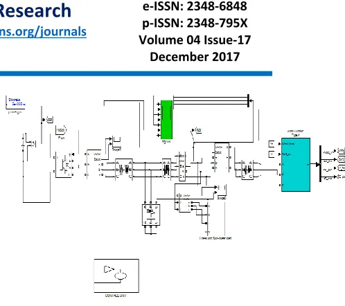
6. SIMULATION RESULTS
Fig 6. Simulation circuit of Windfarm based Without dstatcom
Fig 7. Source current & Load voltage
Fig 8. Wind farm based With dstatcom
Fig 9. Source current,Load voltage,dstatcom currents (a,b,c), Vdc, Load Current
7. CONCLUSION
Available online: https://edupediapublications.org/journals/index.php/IJR/ P a g e | 2265 appropriate estimation of external inductor using
fuzzy logic controller is proposed. A calculation is defined for dynamic reference regulation voltage size generation. The DSTATCOM has enhanced voltage control capacity with a decreased current rating VSI, lessened misfortunes in the VSI and feeder. Additionally, dynamic reference regulation voltage era conspire enables DSTATCOM to set diverse steady reference voltage amid voltage unsettling influences. Reenactment and test comes about approve the adequacy of the proposed arrangement. The external inductor is an exceptionally basic and shabby arrangement for enhancing the voltage direction, be that as it may it remains associated all through the operation and ceaseless voltage drop crosswise over it happens. The future work incorporates operation of this settled inductor as a controlled reactor with the goal that its impact can be limited by differing its inductance.
REFERENCES
[1] M. H. Bollen, Understanding power quality problems. vol. 3, IEEE press New York, 2000.
[2] S. Ostroznik, P. Bajec, and P. Zajec, “A study of a hybrid filter,” IEEE
[3] C. Kumar and M. Mishra, “A voltage-controlled DSTATCOM for powerquality
improvement,” IEEE Trans. Power Del., vol. 29, no. 3, pp. 1499–1507, June 2014.
[4] Q. Liu, L. Peng, Y. Kang, S. Tang, D. Wu, and Y. Qi, “A novel design and optimization method of an LCL filter for a shunt active power filter,”IEEE Trans. Ind. Electron., vol. 61, no. 8, pp. 4000–4010, Aug. 2014.
[5] T. Aziz, M. Hossain, T. Saha, and N. Mithulananthan, “VAR planning with tuning of STATCOM in a DG integrated industrial system,” IEEE Trans. Power Del., vol. 28, no. 2, pp. 875–885, Apr. 2013.
[6] S. Karanki, N. Geddada, Mahesh K. Mishra, and B. Kumar, “A DSTATCOM topology with reduced dc-link voltage rating for load compensation with nonstiff source,” IEEE Trans. Power Electron, vol. 27, no. 3, pp. 1201– 1211, Mar. 2012.
[7] M. Aredes, J. Hafner, and K. Heumann, “Three-phase four-wire shunt active filter control strategies,” IEEE Trans. Power Electron., vol. 12, no. 2, pp. 311–318, Mar. 1997.
[8] B. Singh, K. Al-Haddad, and A. Chandra, “A new control approach to three-phase active filter
for harmonics and reactive power
compensation,” IEEE Trans. Powe Sys., vol. 13, no. 1, pp. 133–138, Feb 1998.
Available online: https://edupediapublications.org/journals/index.php/IJR/ P a g e | 2266 supply with overcurrent handling capability,”
IEEE Trans. Power Electron., vol. 31, no. 4, pp. 2850–2859, April 2016.
[10] H. Fujita and H. Akagi, “Voltage-regulation performance of a shunt active filter intended for installation on a power distribution system,”
[11] R. Gupta, A. Ghosh, and A. Joshi, “Performance comparison of VSCbased shunt and series compensators used for load voltage control in distribution systems,” IEEE Trans. Power Del., vol. 26, no. 1, pp. 268– 278, Jan. 2011.
[12] Mahesh K. Mishra, A. Ghosh, and A. Joshi, “Operation of a DSTATCOM in voltage control mode,” IEEE Trans. Power Del., vol. 18, no. 1,pp. 258–264, Jan. 2003.
AUTHOR DETAILS:
ANNALDAS SAICHARAN
Received b.tech degree from Ayaan college of engineerig and technology, moinabad, rangareddy, telangana in 2014. And currently pursuing m.tech in electrical power system at ellenki college of engineering and technology, patancheru, medak,
telangana. His area of interest in electrical inspection field.
D. PRASADA RAO