High-Throughput Turbo Decoder with Parallel Architecture for
Lte-Wireless Communication Standards
P. Rambabu & S. Rekha
M.Tech (VLSI & ES), St. Mary’s College of Engineering and Technology, Hyderabad Assistant Professor, St. Mary’s College of Engineering and Technology, Hyderabad
Abstract- This work focuses on the VLSI design aspect of high speed maximum a posteriori (MAP) probability decoders which are intrinsic building-blocks of parallel turbo decoders. For the
logarithmic-Bahl–Cocke–Jelinek–Raviv (LBCJR)
algorithm used in MAP decoders, we have presented an ungrouped backward recursion technique for the computation of backward state metrics. Unlike the conventional decoder architectures, MAP decoder based on this technique can be extensively pipelined and retimed to achieve higher clock frequency. Additionally, the state metric normalization technique employed in the design of an add-compare-select-unit (ACSU) has reduced critical path delay of our decoder architecture. We have designed and implemented turbo decoders with 8 and 32 parallel MAP decoders in 90nmCMOStechnology. VLSI implementation of an 8 parallel turbo-decoder has achieved a maximum throughput of 439 Mbps with 0.11 n J/bit/iteration energy-efficiency. Similarly, 32parallel turbo-decoder has achieved a maximum throughput of 1.138 Gbps with an energy-efficiency of 0.079 n J/bit/iteration. These high-throughput decoders meet peak data-rates of 3GPP-LTEandLTE-Advanced standards.
I. INTRODUCTION
Error-correcting coding has become one integral part in nearly all the modern data transmission and storage systems. Low-density parity-check (LDPC) codes are a class of linear codes which provide near-capacity performance on a large collection of data transmission and storage channel while still maintaining implementable decoders. Due to the powerful error-correcting capability, LDPC codes have been used as error-correcting codes with applications in wireless
communications, magnetic and optical recording, and digital television.
Since the first proposition of LDPC codes by Gallager in his 1960 doctoral dissertation, LDPC codes were mostly ignored for the following three decades. One notable exception is the work of Tanner in which a graphical representation of LDPC codes was introduced, now widely called Tanner graph [1]. In mid-nineties, LDPC codes were re-discovered by MacKay, Luby,Wiberg and others. In their works, the sparsity of the parity check matrix of LDPC codes was utilized and belief propagation method proposed by was adopted to significantly reduce the decoding complexity. After that, numerous research efforts have been done and various decoding algorithms are proposed.
The knowledge of binary LDPC codes are the basics for understanding the non-binary counterparts. [2] Developing good code construction method, decent decoding algorithms and efficient decoder architectures are three steps that need to be well coordinated.
In the code designing aspect, the coding theorists are seeking for better codes either for improving the error correcting performance or facilitating the decoder design. Particularly, the class of structured codes constructed through algebraic and combinatorial methods draw much of the attention. The structured codes such as QC-LDPC codes consist of square sub-matrices which can be a permutation or zero matrix. This type of codes are can lead to efficient memory address generation in the decoder.
before [3]. The capacity of the LDPC code under message passing algorithm can be found in. Usually, the density evolution are for analyzing the performance of the constructed random codes derived through computer search.
Several algorithms have been proposed to reduce the computational complexity of the belief propagation algorithm. The most notable work is the Min-sum algorithm. In the Min-sum algorithm, the complicated hyperbolic function in the check node processing for the belief propagation algorithmis reduced to simple comparisons with small performance loss [4]. The normalized and offset min-sum algorithms are proposed shortly afterwards to improve the performance of the proposed Min-sum algorithm. The improvement are mainly due to the alleviation of the overestimation in the original Min-sum algorithm.
II. NB-LDPC DECODING ALGORITHMS
Belief-propagation Algorithm:
LDPC codes can be decoded by the belief propagation (BP) algorithm. In the belief propagation for non-binary codes, the complexity of check node processing dominates. A forward-backward scheme was proposed for BP in to decompose the check node processing into iterative steps [5]. At the cost of larger memory, the number of computations can be significantly reduced. A log-domain variation of the forward-backward scheme was presented.
FFT-based Decoder:
The computations for check node processing can be considered as convolutions of the incoming messages, which can be computed as term by term products in the frequency domain. Using this idea, a fast decoding algorithm for LDPC codes over GF (2p) (p > 1) has been proposed. This algorithm also isolates the effects of the non-binary entries of parity check matrix from check node processing through introducing multiplication/division nodes in the Tanner graph. As a result, the complexity of this algorithm scales with p2p. A variation of this algorithm that uses the logarithm of the channel probability is presented in. Compared to decoders in the probability domain, log-domain decoders are less
sensitive to quantization noise [6]. In addition, multiplications in the probability domain can be converted to additions in the log domain.
Mixed Domain Decoder:
However, computing Fourier transform in the log domain is very difficult. To take advantage of both log-domain decoding and simplified convolution computation in the frequency domain, a mixed-domain decoder is proposed. In this decoder, the Fourier transform is done in the probability domain and the check and variable node processing is carried out in the log domain.
In three serial NB-LDPC decoders, in which the processing of one check or variable node is carried out at a time, have been implemented on FPGA devices. Among these decoders, the one in the mixed domain is the most efficient. However, it can only achieve around 1 Mbps throughput with large hardware resource. In addition, the memory requirement will increase significantly when the order of the finite field becomes higher.
Extended Min-sum (EMS) Algorithm:
Despite the simplified check node processing, frequency-domain de-coders demand a large number of multiplications and extra complexity forthe Fourier and inverse transforms. In addition, mixed-domain decoders re-quire large memory to implement the look-up tables (LUTs) that are needed for the conversions between the domains. On the other hand, the extended Min-sum algorithm (EMS), which is an approximation of the belief propagation in the log domain and an extension of the Min-sum algorithm for binary LDPC codes [50], requires only additions in the check node processing. With proper scaling or offsetting, the EMS algorithm only leads to less than 0.1dB coding gain loss compared to the belief propagation. To reduce the memory requirement, it was also proposed to keep nm< q messages on each edge of the Tanner graph at the cost of small performance degradation.
Path construction based check node processing for Min-max algorithm:
NB-LDPC decoding are proposed. Employingthe Min-max algorithm, each c-to-v probability from a check node equals one of only a few most reliable v-to-c probabilities to this node. Based on this observation, a limited number of the most reliable v-to-c messages are first sorted out. These messages can be considered as nodes in a trellis. Then the c-to-v messages to all connected variable nodes are generated independently using a path construction scheme without storing other intermediate values. As a result, both the memory requirement and logic gate count can be reduced significantly without sacrificing the speed. Compared to the forward-backward check node unit (CNU) architecture, the proposed architecture can reduce the memory and area requirements to 19.5% and 22.5%, respectively, when applied to a (837, 726) NB-LDPC code overGF(25).It is a challenging task to compute vm,n from the corresponding most reliable v-to-c messages, especially when only the nm most reliable entries of
vm,n are needed, and it is desired not to waste computations on the rest unreliable entries. In this subsection, a novel path construction scheme is presented to efficiently derive the smallest LLRs in
vm,n from the corresponding sorted smallest v-to-c LLRs.
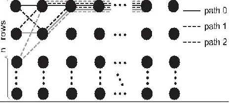
For a check node, the messages from the dc connected variable nodes can be represented by a trellis of dc
stages. Each stage has nm nodes, representing the nm
entries in the corresponding v-to-c message vector. Fig. 2.1 shows such a trellis. Note that the nodes in a stage are ordered according to increasing LLR, and the normalization in (2.1) guarantees that the nodes in the first row have zero LLR.
Figure 1: Trellis of variable-to-check messages
Corresponds to a path in the trellis that is formed by
connecting the nodes with ajin thejthstage. Such a path passes exactly one node in each stage, exceptthe stage for variable node n. Define the LLR and finite field element of a path the maximum of the LLRs and sum of finite field elements, respectively, of all nodes in the path. Accordingly, computing the nm entries of
vm,n with the smallest LLRs is equivalent to finding the nm paths with the smallest LLRs and different finite field elements that pass exactly one node in each stage, except the stage for variable node n. Apparently, the path that passes only the zero-LLR nodes in the first row of the trellis is the path with the smallest LLR. This path is denoted by path 0 in Fig 2.1. Assume that all dc× (nm− 1) nonzero LLRs of the trellis can be sorted in non-decreasing order as x(1), x(2),· · · . Their associated field elements are α(1), α(2),· · · , and they belong to variable nodes with indices e(1), e(2), · · · . The other paths forvm,ncomputation can be constructed iteratively by changing nodes in path 0 to nonzero-LLR nodes with
e(i) _= n.
To ensure that the paths with the smallest LLRs are constructed first, so that no computation is wasted on calculating the unreliable c-to-v messages that will not be stored, the nonzero-LLR nodes are included in the path construction gradually according to increasing LLR. In another word, the node corresponding to x(i) will be considered for path construction before the node corresponding to x(i + 1).
Error Correcting Performance of Extended Min-sum and Min-max algorithm:
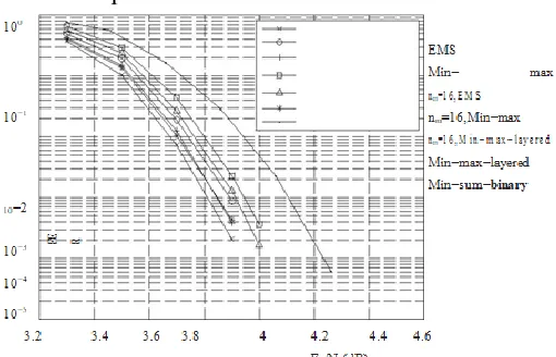
Compared to the EMS algorithm,um,j(aj) is replaced byj∈Sv(m)\nmax um,j (aj ) in (2.3). As a result, the Min-max algorithm can be implemented by a more efficient architecture as will be shown in later chapters of the thesis. On the other hand, the performance of the Min-max algorithm is only slightly worse. Fig. 2.2 and 2.3 show respectively the frame error rates (FERs) and bit error rates (BERs) of the EMS and Min-max algorithms for a (744, 653) QCNB-LDPC code over GF (25) with 15 decoding iterations under the additive.
constructed using the method based on the multiplicative group of a finite field proposed. In this construction, a r×t sub-matrix is first picked from a cyclic matrix whose first row is (0, α−1,· · ·, αq−2−1). Here α is a primitive element.
Figure 2: FERs of a (744, 653) NB-LDPC code over GF (25) and a (3683, 3175)
Binary LDPC code under AWGN channelof GF (q), and r≤q and t < q depend on the length and rate of the code needs to be constructed.Then the H matrix is formed by dispersing each element in the picked sub-matrix to a sub-matrix of dimension (q− 1) × (q− 1). The first row of the matrix resulted from dispersing an element αi is all zero, except that the ith entry is αi. Each of the other rows is a right cyclic-shift of the previous row multipliedby α. For the (744, 653) code construction, r = 24 and t = 3 are used. As it can be observed from Fig. 2.2, the Min-max algorithm has only around 0.08dB performance degradation at FER=10−3 compared to the EMS algorithm for the (744, 653) code. In the decoding of NB-LDPC codes, a vector of q messages needs to be recorded for each edge of the Tanner graph. This leads to vast memory requirement, especially when the order of the finite field is large.
In order to reduce the memory requirement, it was proposed to keep only the nm< q most reliable messages for each vector.
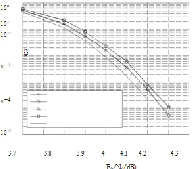
Figure 3: BERs of a (744, 653) NB-LDPC code over GF (25) and a (3683, 3175) binary LDPC code
under AWGN channel
A similar idea can be applied to the Min-max algorithm: keeping only the nm< q messages with the smallest LLRs in each vector. As it can be observed from Fig. 2.2, keeping only nm = 16 messages for the (744, 653) code constructed over GF (25) only leads to around 0.045dB performance loss in the Min-max algorithm. For reference, Fig. 2.2 and 2.3 also show the performance of a binary (3683, 3175) code constructed with the method using the Min-sum decoding. This binary code has similar code rate and code word length in terms of bits as the (744, 653) NB-LDPC code over GF (25).To show the effect of the Min-max decoding and keeping nm< q messages on a different code, Fig. 2.4 and 2.5 illustrate the performance of a (248, 124) code over GF (25). This code has much shorter length and lower rate than the (744, 653) code.
Figure 4: BERs of a (248, 124) NB-LDPC code over GF (25) and a (1270, 635) binaryLDPC code under AWGN channel to 0.02dB performance loss The IHRB-MLGD and ISRB-MLGD Algorithm:
In partial-parallel architectures are developed to efficiently implement the IHRB-MLGD and ISRB-MLGD algorithm through algorithmic and architectural optimizations.In the IHRB algorithm, the reliability measures of the received symbols are updated in each iteration based on the hard-decision symbols. Throughout this paper, the superscript (k) is added to denote the values in the kth decoding iteration whenever necessary.
Figure 5: FER of a (837, 726) QCNB-LDPC code over GF (25) with 15 iterations and nm = 16
”Clipping” method in is applied to subtract the same value from each reliability measure in a vector, so that the largest measure remains γ. For those reliability measures become negative after the
subtraction, zero is used instead. Accordingly, the reliability measures will remain as integers in the range of [0, γ]. Moreover, σi,j is the extrinsic check sum from check node i to variable node j. The decoding can be stopped when a codeword is found, or the maximum decoding iteration number, Imax, is reached.
III. PARALLEL TURBO-DECODE
This work focuses on the VLSI design aspect of high speed maximum a posteriori (MAP) probability decoders which are intrinsic building-blocks of parallel turbo decoders. For the logarithmic-Bahl– Cocke–Jelinek–Raviv (LBCJR) algorithm used in MAP decoders, we have presented an ungrouped backward recursion technique for the computation of backward state metrics. Unlike the conventional decoder architectures, MAP decoder based on this technique can be extensively pipelined and retimed to achieve higher clock frequency. Additionally, the state metric normalization technique employed in the design of an add-compare- select-unit (ACSU) has reduced critical path delay of our decoder architecture. We have designed and implemented turbo decoders with 8 and64 parallel MAP decoders in 90nmCMOStechnology. VLSI implementation of an 8 parallel turbo-decoder has achieved a maximum throughput of 439 Mbps with 0.11 nJ/bit/iteration energy-efficiency. Similarly, 64 parallel turbo-decoder has achieved a maximum throughput of 3.3 Gbps with an energy-efficiency of 0.079 nJ/bit/iteration. These high-throughput decoders meet peak data-rates of 3GPP-LTEandLTE-Advanced standards.
IV. LBCJR ALGORITHM
Modified Sliding Window Approach:
ungrouped backward recursion for th stage begins from th stage in the trellis graph. Each of these backward recursions is initiated with logarithmic-equiprobable values assigned to all the backward state metrics of the trellis stage.
Simultaneously, the branch metrics are computed for successive trellis stages and are used for determining the state metric values using (2). After computing backward state metrics of th trellis stage by an ungrouped backward recursion, all the forward state metrics of the trellis stage are computed. It is to be noted that the forward recursion starts.
Thereafter, a posterioriLLR value of putted using the branch metrics of all state transitions, as well as forward and backward state metrics from th and th trellis stages, respectively, as given in (4). Paralleling such ungrouped backward recursions for successive trellis stages in order to compute their a
posteriori LLRs is a primary concern of our work.
For the sake of clarity, we have used handful of new notations while explaining this approach for LBCJR algorithm. For example, and represent sets of backward and forward state metrics, respectively, of th trellis stage. They are expressed as and where is a set of natural numbers including zero.
Fig. 6: (a) Illustration of ungrouped backward recursions in a trellis graph of
four states. (b) Scheduling of the modified sliding window approach for LBCJR
First ungrouped backward recursion ends in this interval with the computation of effective-set for trellis stage. In parallel, second ungrouped backward recursion continues with the computation of consecutive-set. Similarly, a new-set is computed and it marks the start of third ungrouped backward recursion.
: An effective-set is obtained with the termination of second ungrouped backward recursion and a consecutive-set is computed for an ongoing third ungrouped backward recursion. Simultaneously, fourth ungrouped backward recursion begins with the computation of a new-set. Using an initialized set, a set of forward state metrics is determined.
Backward and branch metrics from the set , and respectively. From this interval onward, similar pattern of operations are carried out for each time-interval where an ungrouped backward recursion is terminated with the calculation of an effective-set; a consecutive-set is obtained to continue an incomplete ungrouped backward recursion and a new-set is determined using the initialized values of backward state metrics to start an ungrouped backward recursion. Simultaneously, sets of forward state metrics and a posterioriLLRs for successive trellis stages are obtained from interval onward.
Total REAL time to Xst completion: 0.00 secs Total CPU time to Xst completion: 0.11 secs
--> Parameter xsthdpdir set to xst
Total REAL time to Xst completion: 0.00 secs Total CPU time to Xst completion: 0.11 secs
--> Reading design: inst1.prj
Here we can implement the RTL schematic by usingXilinix 13.1 software. we can get 32 bit decoded output as ( b17-b31 b0-b16) .
FIG.7: Implementation of RTL schematic of turbo decoder with parallel architecture
It can be executed after implement a top module(combination of all modules) and then in the simulation behaviour we can simulate the results as shown in below figures. we can observe the inputs and out puts. Let us consider input as 00000000000000000000000000000101 ( b31b30
-b17b16- - - -b1 b0 ) then we get the output as
00000000000000001010000000000000 (b17b18
-b31b0- - -b15b16).
Fig.8: Input (0)10 is transmitted to decoder (initially decoder is in undefined state).
Fig 9: Input (1)10 is transmitted to decoder
Fig 10: Input (2)10 is transmitted to decoder
Fig 11: Output for finding critical path.
VI. CONCLUSION
in data-rate for next-generation wireless-communication and this will lead to more complex algorithms and VLSI architectures in next few decades.
Based on this scenario, we have aggregated the study of turbo-code and the design of high-throughput parallel-turbo decoder in this thesis. To this end, we have realized the importance of understanding an algorithm in real-world scenario and then realizing application specific architecture for it. Thereby, it is essential to explore both algorithmic as well as architectural sides of wireless-communication system to conceive a best design that meets the requirement of next-generation technology.
REFERENCES
[1] Rahul Shrestha and Roy Paily, \Comparative Study of Simplified MAP Algorithms and an Implementation of Non-Parallel-Radix-2 Turbo Decoder," Journal of Signal ProcessingSystems - Springer, (DOI: 10.1007/s11265-014-0951-7, In Press - September-2014).
[2] Rahul Shrestha and Roy Paily, \High-Throughput Turbo Decoder with Parallel
Architecture for LTE Wireless
Communication Standards," IEEE
Transactions on Circuits and Systems I: Regular Papers, Volume: 61, Issue: 9, pp. 2699-2710, September-2014.
[3] Rahul Shrestha and Roy Paily, \Performance and Throughput Analysis of Turbo Decoder for the Physical Layer of Digital Video Broadcasting - Satellite-services to Handhelds (DVB-SH) Standard," Journals of IET Communications, Volume: 7, Issue: 12, pp. 1211-1220, 2013.
[4] Rahul Shrestha and Roy Paily, \Design and Implementation of a Linear Feedback Shift Register Interweaver for Turbo Decoding," Springer Berlin/Heidelberg Lecture Notes inComputer Science, Volume: 7373, pp. 30-39, 2012.
[5] Rahul Shrestha and Roy Paily, \Hardware Implementation of Max-Log-MAP Algorithm Based on Maclaurin Series for Turbo Decoder," IEEE International Conference on Communications and Signal Processing (ICCSP), pp. 509-511, 2011.
[6] Vijaya Kumar K, Rahul Shrestha and Roy Paily, \Design and Implementation of Multi-Rate LDPC Decoder for IEEE 802.16e Wireless Standard," IEEE International
Conferenceon Green Computing,