Multiphysics Model of Iron Powder Compacts for Efficient
Microwave Processing
Jutika Devi1, *, Mohammad J. Akhtar2, and Pranayee Datta1
Abstract—A generalized multiphysics model using COMSOL Multiphysics software for optimizing the sintering process of iron powders having various green densities is developed. The modeling is facilitated by designing a 30 GHz multimode applicator, where the test sample is placed for the microwave processing. The effective dielectric and magnetic properties of the resultant metal powder compact is estimated using the effective electromagnetic model considering the idea of core-shell particle approach followed by the Lichtenecker’s mixture formula. A theoretical approach relating the penetration depth, proper impedance matching and volume fraction of different density powder compacts is also discussed here. From the study, it is clear that the effective dielectric and magnetic properties contribute to the microwave sintering process of metal powders.
1. INTRODUCTION
For sintering of various materials such as ceramic, metal matrix composites and metal powder compacts, there is lots of interest nowadays to use the microwave energy as it offers several advantages such as the volumetric and selective heating, improved product quality, energy savings, self cooling system, better precision in controlling the process of energy deposition, and reduction in manufacturing costs, over the conventional heating methods [1, 2]. In recent years, the iron powders are widely investigated for their applicability in many fields such as for various strategic applications, magnetic applications, in electronic industry as RF transformers, EMI filters, switch mode power supplies, and absorbent fillers. The iron powder compacts are also found to be very good microwave material for various industrial heating applications due to their magnetic behaviour in the microwave and mm wave frequency range apart from their dielectric behaviour. For processing ceramics, metal oxide and composite materials, the 2.45 GHz single mode and multimode applicators were mostly used till now for various kinds of samples. However it has become evident in the last decade that many microwave energy applications might be greatly benefited from an increase in the frequency of radiation [3]. There is a growing demand of very high frequency power sources for processing of metal powder compacts to take the benefits of very high uniformity of heating, reduced applied power as well as the compact applicator resulting more homogenous field distribution. The 30 GHz processing has high potential application in the field of thermal barrier coating, joining of high temperature superconductor ceramic coatings to metal substrates, surface transient heating of metal alloys, heating of powdered metal, etc. [3– 6]. Reduction of the sintering time with higher heating rate in 30 GHz processing reduces grain growth in the joint zone with higher mechanical strength of the joint [7]. The growing interest in the nanostructured materials for their great potential for various applications has also made 30 GHz sintering a very important area of study [4, 8]. A successful use of millimetre wave heating to sinter materials, such as boron carbide, alumina, silicon nitride, zinc oxide, and copper powder, has been
Received 13 February 2017, Accepted 28 March 2017, Scheduled 14 April 2017
* Corresponding author: Jutika Devi ([email protected]).
1 Department of Electronics & Communication Technology, Gauhati University, Assam 781014, India. 2 Department of Electrical
reported [5, 9]. However, most of the reported studies do not provide detailed explanation of the observed heating patterns of metal powders, and there is also not much information available to interpret the mechanism of microwave hearting of these powders. In order to understand the heating phenomenon of metal powders, these powders should be considered as lossy dielectrics, and accordingly their equivalent constitutive properties should be determined. The penetration depth is a very important parameter of the workload because it gives an immediate first order indication of the heat distribution within it [10]. The aim of this work is to perform a detailed study of the microwave heating phenomenon of iron powder compacts at 30 GHz, which is facilitated by designing an applicator based on the microwave applicator design theory. The study involves the multiphysics modeling of these pure metal powders as specialized compact thereby taking into account the concept of the complex effective permittivity and permeability. In this study, the effective permittivity and permeability of iron powder of various densities are estimated at room temperature using the effective medium theory considering the fact that the metal particles are core which are coated by dielectric oxide shell, and this core-shell arrangement is randomly distributed in air medium. The Lichtenecker’s logarithmic mixture formula [11] is used to calculate the effective permittivity and permeability of the iron powder samples in terms of volume ratio and material properties of the constitutive materials.
After estimating the effective constitute properties of iron powders at room temperature, these values are also computed at the higher temperature so that the temperature dependent electromagnetic properties can be used in the study as model input to study various behaviours of the test samples in a more realistic way. The knowledge of effective dielectric properties of materials as a function of temperature is also important for various other fields such as the microwave processing, microwave propagation microwave retorting, and in the aircraft and missile. However, practically it is difficult to measure the temperature dependent dielectric and magnetic properties of metal powders. Larsson et al. [12] proposed a quite general method to determine the dielectric properties at elevated temperatures from the room temperature data, which is applicable for materials of various types. In this paper, this method is used to extend the estimated room temperature constitutive properties data of iron powder to higher temperatures.
The better stability against the thermal runway effect is quite important for the effective microwave/mm-wave sintering of various materials. The problem of thermal runway becomes less severe with an increase in the frequency of the radiation used for heating and hence, application of millimetre wave power for the high temperature processing of materials is very much favourable [3, 4]. Following the typical microwave volumetric heating, there are temperature gradients presents within the workload which cause the heat to flow from hot to cool areas, with the whole mass eventually reaching a constant equilibrium temperature [13]. The temperature gradient developed in the microwave heated sample depends on the thermal insulation, the intensity and spatial distribution of microwave power absorption for the particular test specimen [4]. Although significant progress has been made in the experimental and numerical analysis of 2.45 GHz microwave processing, to the best of the authors’ knowledge, very few multiphysics simulation works have been carried out to study the microwave heating mechanism of metal powder compacts considering the detailed heating mechanism. Simulation on millimetre wave processing of metal powder compact has been remaining as an open problem for long time, which makes very high demand for development of appropriate models for the high temperature 30 GHz processing technologies for these materials [4]. Motivated by this, a multiphysics model is developed to study the high temperature 30 GHz processing of metal powder compacts.
2. ANALYTICAL APPROACH, MODELING AND SIMULATION 2.1. Analytical Expressions
The aim of this section is to revisit some closed form analytical expressions, which are quite useful in order to understand the basic heating mechanism using the microwave energy. It may be mentioned here that in the past, the microwave heating phenomenon was usually considered for nonmagnetic dielectrics, and hence all the related parameters, such as penetration depth and power loss, were accordingly defined by taking into account only the dielectric losses. However, for the magnetic metallic powders such as iron powder compacts, these parameters should be redefined by taking into account both the dielectric and magnetic properties in order to fully understand the microwave heating mechanism. In addition, the role of various other electromagnetic parameters such as intrinsic impedance and transmitted power density, on the microwave heating of magnetic metallic powders should also be clearly understood.
First of all, we define here the complex propagation constant for the magnetic metal powders as follows:
γ = jω√με≡α+jβ
=
−ω2ε
0μ0(μrεr−μrεr) +jω2μ0ε0(μrεr+εrμr) (1) where α is the attenuation constant, β the phase constant, ε = ε0εr = ε0 (ε
r−jε
r) the complex permittivity with ε0 being the free space permittivity, εr being the complex relative permittivity, and
εr and ε
r being its real and imaginary parts, respectively. Similarly, the magnetic permeability in the above equation is defined asμ=μ0μr=μ0(μ
rjμ
r) with μ0 being the free space permeability, μr being the complex relative permeability, andμr andμ
r being its real and imaginary parts, respectively. By separating the real and the imaginary parts of the above equation and simplifying them, the obtained equations are
α=ω
ε0μ0
2
1 2
εrμ
r −ε
rμ
r+
εrμ
r
2
+
εrμ
r
2
+
εrμ
r
2
+
μrε
r
21/21/2
(2)
and
β =ω
ε0μ0
2
1 2
εrμ
r+ε
rμ
r+
εrμ
r
2
+
εrμ
r
2
+
εrμ
r
2
+
μrε
r
21/21/2
(3)
Writing in terms of the free space wave length corresponding to the operating frequency, the expression for the attenuation constant can be written as
α= √
2
λ0π
εrμ
r−ε
rμ
r+
εrμ
r
2
+
εrμ
r
2
+
εrμ
r
2
+
μrε
r
21/21/2
(4)
Now, one of the important parameters to understand the microwave heating phenomenon is the penetration depth, which is defined as the distance at which the electromagnetic wave gets attenuated to 1/e (36.8%) of its initial value in terms of the power density. This parameter can be expressed in terms of the attenuation constant as follows [17]:
Dp = 1 2α
= λ0 2√2π
εrμr−εrμr+
εrμr
2
+
εrμr
2
+
εrμr
2
+ (μrεr)2
1/2−1/2
(5)
For a nonmagnetic material having μr= 1 and μ
r = 0, the above equation would reduce to:
Dp = λ0 2π 2εr
1 ⎡ ⎣ ⎧ ⎨ ⎩1 +
εr
εr
2⎫⎬
⎭ 0.5
−1
⎤ ⎦
which is actually the same as the expression commonly available in literature to calculate the penetration depth of purely dielectric materials [6]. If the test specimen is magnetic, but the magnetic losses are not significant, i.e.,μr = 1 andμ
r = 0, then Eq. (6) will be simplified to the following form:
Dp = λ0 2π 2εrμr
1 ⎡ ⎣ ⎧ ⎨ ⎩1 +
εr
εr
2⎫⎬
⎭ 0.5
−1
⎤ ⎦
(7)
Now, apart from the penetration depth, one parameter which is equally important for the microwave heating behaviour of the various test specimens is the transmitted power in the workload. The transmitted power would also depend upon the intrinsic impedance η =
μ
ε of the medium under test apart from the incident power. When an electromagnetic wave is incident from the background medium on the test medium having intrinsic impedance different from that of the medium in which the wave is originated, a part of the incident power is reflected and the other part is transmitted. It is always highly desirable for the efficient microwave heating that the maximum power is transmitted to the workload with minimum reflection. This would usually require that the load is matched to the impedance of the background medium making the standing wave ratio to be unity under the ideal situation. The density of power transmitted across the interface can be defined as [15]:
Ptrans = Pinc
1− |Γ|2
(8)
= Pinc
η1
η2τ 2
(9)
where,Pinc= E 2 0
η is the incident power density, and Γ andτare defined as the reflection and transmission coefficients, respectively related by the following equation —
Γ = η2−η1
η2+η1
; 1 + Γ =τ (10)
It can be observed from the above sets of equations that for a given applied input power, the transmitted power density inside a test sample would depend on the reflection coefficient, which in turn would depend upon the extent of mismatch between the test medium and the background medium. Using the proposed analytical approach, the penetration depth and transmitted power density inside the magnetic powder samples of various green densities samples can be computed for a given input power. To understand the metal powder-microwave interaction and to process the metal powder compacts in an efficient way using the microwave energy, the proposed theoretical approach would be a promising tool as it would minimize the number of iterations in order to arrive at the optimized process cycle for a given workload.
2.2. Design of the Multimode Applicator
Microwave applicator is specially designed to process various types of workloads by exposing them to electromagnetic fields, considering various aspects of the microwave-material interaction to achieve better quality factor with higher efficiency. Constructive interference of the electromagnetic waves inside the cavity is possible only when the dimension and shape of the applicator is made appropriate for that particular operating frequency. The designed cavity is usually a rectangular box having dimensions with width (a), height (b) and depth (d), in which width and depth are more than several half wavelengths [16]. For 30 GHz operating frequency, the guide wavelength (λg) is 14.14 mm. The designed rectangular
cavity is of dimension (26.7 mm×27 mm×18.8 mm) where width and depth are more than 3λg/2.
the resonant cavity of dimension (a×d×b), the resonant free space wavelengths (λores) obtained within
the empty rectangular cavity is given by:
2
λores 2
=
m
a
2
+
n
b
2
+
p
d
2
(11)
wherem, n,pare the highest integers satisfying the conditionm < 2λoa, n <≤ λo2b andp < 2λod, respectively and are known as mode set numbers. The uniform heating pattern in the loads depends on the number of modes having resonant frequency within a specified bandwidth which can be considered as the figure of merit (FOM) of the oven. Again, for the applicator having planes of symmetry, to avoid degeneracy, we have taken the aspect ratio as u = ba and v = da which is 0.704 and 1.01, respectively. The few possible modes for the cavity of dimension (26.7 mm×27 mm×18.8 mm) resonant at 30 GHz frequency are obtained through the various permutations of (m, n, p), which are given below.
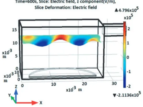
Figure 1. The designed applicator for 30 GHz operating frequency showing the electric field distribution.
Table 1. Permutations of few possible modes (m, n, p) for the designed applicator resonant at 30 GHz.
λo res(mm) m n p
10.5 3 2 3
9.6 2 3 3
10.3 4 1 3
9.6 5 1 2
10.4 2 3 2
aThe unit of resonant free space wavelength (λ
o res) is in millimetre (mm).
2.3. Estimation of Effective Constitutive Properties
For estimating the effective relative permittivity of the metal powders, the core-shell particle model with air as the host medium is used. For iron powder compacts, the core is of pure iron and the shell is of iron oxide (Fe2O3). The complex relative permittivity values of the initial constituents used in
the estimation of the effective permittivity of metal powder compacts for a particular frequency are not always available in literature and hence, they have to be calculated using the basic microwave theory. The complex relative permittivity of the pure iron particle is calculated using the expression
ε∗r =εr−jεr whereεr =σ/ωε
0 [18]. Here, σ is the electrical conductivity which is 1.04×10
7S/m for
iron, free space permittivity ε0 = 8.85×10⁻¹²F/m and ω = 2πf is the angular frequency with the
applied frequencyf = 30 GHz, andεr is taken as 1 for iron [18]. The complex relative permittivity and permeability values of the dielectric oxide shells used in the present study are taken from the published data [19]. The particle size for the iron powder is taken as 74µm which is closer to 200 meshes [19], and the shape of the particle is considered to be spherical in average sense for modeling. The relative permeability of iron is μr= 4000 [18].
The core-shell model proposed by the effective medium theory basically considers the metal powder compact as a composite medium, where in a dielectric oxide shell is introduced between the metal particle sand the surrounding air medium [19, 20]. After modelling the core shell particles, the Lichtenker’s logarithmic mixture formula is used to estimate the complex effective relative permittivity of the effective medium where core-shell particles are randomly distributed in air and the volume fraction of both the metal core-dielectric shell particle and air is taken into account. In this analytical model, since the core-shell particle is a component of mixture, the size and shape of the particle is also taken into account, thereby modifying the conventional two phase approach of the mixture formula more practically. The effective thermal properties are estimated taking account of the thermal properties of the bulk metals [21] and the volume ratio. The effective dielectric and magnetic properties strongly depend on volume fraction [22]. Both the real and imaginary parts of effective permittivity increase with the volume fraction. For different volume ratios of material under test and porosity, the effective permeability of the iron powder compacts are different and increase with volume fraction, which is also estimated using the Lichtenker’s logarithmic mixture formula.
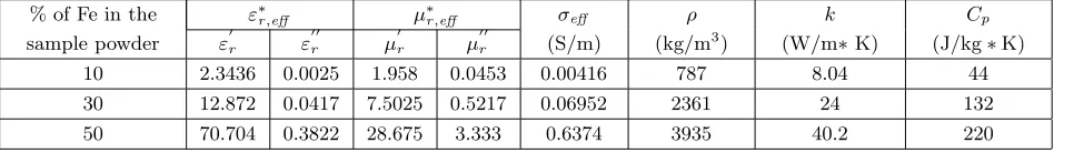
Effective properties of various green densities iron powder compacts at room temperature for 30 GHz operating frequency are given in Table 2.
Table 2. Effective electrical and thermal parameters of iron powder compacts.
% of Fe in the sample powder
ε∗
r,eff μ∗r,eff σeff
(S/m)
ρ (kg/m3)
k (W/m∗K)
Cp (J/kg∗K)
εr ε
r μ
r μ
r
10 2.3436 0.0025 1.958 0.0453 0.00416 787 8.04 44
30 12.872 0.0417 7.5025 0.5217 0.06952 2361 24 132
50 70.704 0.3822 28.675 3.333 0.6374 3935 40.2 220
aHere,ε∗
r,eff, μ∗r,eff, andσeff denote effective permittivity, effective permeability and effective conductivity of the Fe powder compacts respectively. The units S = Siemens and m = meter. ρ,KandCpare the effective density, effective
thermal conductivity and effective specific heat capacity of the Fe powder compacts respectively. The units kg = kilogram, m = meter, W = watt, K = Kelvin and J = Joule respectively.
The estimated room temperature permittivity data of iron powder are extended to higher temperature by fitting them to our modelled functions which, gives the temperature dependent permittivity profile of iron powder compacts considering the method reported in [12]. The estimated dielectric properties of 10% iron powders are fitted to our modelled function and the obtained temperature dependent dielectric function profile is given below.
For 10% Iron powder:
εr(T) =εr0+ 0.065182∗(T−T0) +j0.001∗(T −T0) (12)
The temperature dependent effective conductivity for the powder compacts is calculated from the corresponding data forεr at 30 GHz and incorporated as the model input using COMSOL Multiphysics software. Density, specific heat capacity and thermal conductivity of the studied powders are assumed constant with respect to temperature in this study. However, the specific heat capacity of iron powder compact can be made temperature dependent considering the temperature dependent heat capacity function [23, 24] expressed as:
Cp= 4.1868
a+ 10−3∗b∗T−56.92∗T−21 JK−1mol−1 (13) where, a&b are constants andT = temperature in K. For iron,a= 8.873 &b= 1.474.
It is worth mentioning that use of temperature dependent Cp as model input will make the high temperature processing of iron powder more effective.
2.4. Heat Conduction Equation for Coupled Electromagnetic-Thermal Interaction
The two physical processes that can form an appropriate basis for the process of microwave heating are electromagnetic wave propagation and heat diffusion. In this model, we combine the propagation of the electromagnetic wave with the heat transfer equation in order to get the sintering temperature distributions and other system properties. The heat transfer equation can be described using the following equation:
ρCp
∂T
∂t − ∇ ·(k∇T) = ˙q (14)
where, ρ, Cp and k are the density, specific heat capacity and thermal conductivity, respectively. T is the temperature, and t is the process time. The parameter ˙q in the above equation represents the total electromagnetic heating source including the Joule resistive loss and the electromagnetic power dissipated per unit volume, as given by
˙
q =σE2+1 2
ωε0ε
eff |E|2+ωμ0μ
effH2
(15)
E and H in the above equation represent the electric and magnetic fields, respectively, and the 1st term on the RHS denotes the Joule resistive loss while the 2nd term denotes the electromagnetic power dissipation per unit volume. From the above equation, it is clear that the electromagnetic energy losses are dominated by E and Hfields and depend on the dielectric and magnetic loss factors εeff and μeff
which contribute to the power dissipation in the workloads.
3. METHOD
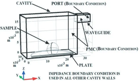
The efficient microwave sintering process requires optimization of various parameters, which is quite complex. The multiphysics modeling becomes a quite effective tool for the study of sintering process as the effects of the various parameters on the overall process can be accurately incorporated, and these parameters can be ultimately optimized for the efficient microwave processing, thereby minimizing the number of iterations required during the actual sintering. The modeling of microwave heating involves solving the Maxwell’s electromagnetic equations simultaneously with the heat transfer equation by applying the appropriate boundary conditions. The schematic illustration of the system geometry along with applied boundary conditions is shown in Figure 2.
Figure 2. Schematic illustration of the system geometry along with applied boundary conditions.
system geometry made of different materials allow in this study to perform the coupled multiphysics simulation by solving the required iteration steps with better control on local mesh refining [25, 26]. Since the cavity atmosphere can affect the thermal and electrical parameters of the compact, we have used air as insulator in this study. The initial temperature for both the sample and insulator is kept uniform at 25◦.
4. RESULTS AND DISCUSSION 4.1. Model Validation
In order to validate the proposed model, we have studied the heating profile of 75% density iron powder compact at 30 GHz, considering sample size (10×4×4) mm3 as reported in [3]. Applying 3.7 kW power, keeping the sample at the middle of the cavity, i.e., at the electric field maximum position, simulation has been done for 1200 seconds, to obtain the sintering temperature within the sample volume. The sintering temperature reaches 970◦C at 1200 seconds, which is in very good agreement with the reported experimental work [3] as shown in Figure 3. Good agreement between the simulated and measured results testifies the efficiency and accuracy of the present model for high temperature processing of different density iron powder compacts.
After validation of the present model, we compare the heating behaviour of different density iron powder compacts using conventional heating and 30 GHz heating mechanism.
4.2. Comparison of 30 GHz and Conventional Heating
The multiphysics simulation of microwave and conventional heating of spherical iron powder compact samples of diameter 6 mm is performed, and a comparison is shown in Figure 4. The electrical and thermal parameters given by Table 2 are used as the model input. The iron powder compact samples of 10%, 30% and 50% densities are exposed to the microwave energy radiation using different power levels by maintaining the heating rate of 150◦/minute, and placing it at the electric field maximum position, i.e., at the middle of the cavity. It is found that for all the cases of iron powder compacts, it reaches sintering temperature of 1252◦ within 6 minutes.
4.3. Heating Mechanism of 10% Density Iron Powder Compact
Figure 3. Heating profile of 75% density iron powder compact sample at the centre of the sample.
Figure 4. Temperature-Time profile of iron powder compact showing 30 GHz microwave heating and conventional heating.
Figure 5. Temperature and electric field distribution in the compact of 10% iron powder of diameter 6 mm placed at the middle of the cavity (i.e., at the electric field maximum position) with applied power 500 Watt.
From Figure 5, it is seen that there are three peaks in the electric field distribution after placing the sample at electric field maximum position. In comparison with the electric field distribution without any sample, no obvious alternation in the electric field distributions and in the intensity is observed and hence, no significant modification in the resonance mode is achieved. Similarly, one can also find the information of electric field minimum position and magnetic field maximum position and thus, the effect of the field distribution on the heating mechanism. It is observed that low density iron powder compact is heated very well at electric field maximum position. The distribution of temperature is uniform throughout the sample which supports the volumetric heating of 10% density iron powder compact.
Figure 6. Resistive losses for the compact of 10% iron powder of diameter 6 mm placed at the middle of cavity (i.e., at the electric field maximum position) with applied power 500 Watt.
samples is volumetric whereas the surface heating is monitored in higher green densities samples. The study is repeated for 10%, 30% and 50% iron powder compacts using the same applied power of 500 watt, and the maximum temperature rises after 1000 seconds process time are found to be 1598.9◦, 1162.8◦ and 181.08◦, respectively. From the analysis, it is clear that the selective heating using the controlled input power can lead to optimized heating pattern for the metal powder compact having various green densities. In the case of iron powders, the sintering temperature is achieved at faster heating rate which may be due to the ferromagnetic effects such as higher magnetization, stronger magnetic susceptibility as well as hysteresis loss. The magnetic permeability parameter also contributes to the microwave heating mechanism of iron powder compact. The temperature gradient profile for 10% density iron powder compact is shown in Figure 7. The maximum negative temperature gradient is obtained at (1.52 mm in
xdirection & 0.17 mm inzdirection) from the centre of the sample. The temperature gradient not only depends on density but also depends on the penetration depth of the metallic powder compact and the optimized sample dimension. The dependency can be correlated to the effective constitutive dielectric properties of the test samples, particle size of the powdered material, and thickness and nature of the oxide shell coated on the metal particles.
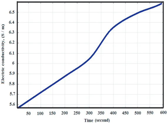
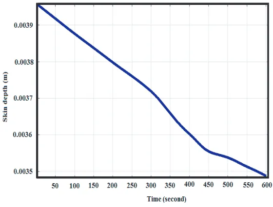
If the temperature dependent properties of dielectric constant and loss factors are known, the microwave absorption can be determined accurately. The dielectric property data reveals the microwave heating trends for the material, facilitating the design of higher efficiency systems. It is observed that the dielectric constant and loss factor for the 10% density iron powder compacts increase slightly with temperature, whereas the penetration depth for the samples decreases with time. For 10% iron powder compact, the variation of effective conductivity and the penetration depth with temperature during the processing are shown by Figures 8 and 9, respectively.
Figure 7. Temperature gradient evolution in 10% iron powder compact using heating rate of 150 per minute when placed at the middle of the cavity (i.e., at the electric field maximum position) with applied power 500 Watt.
Figure 8. Variation of effective conductivity with time for 10% iron powder compact.
minimize the developed temperature gradients inside the workloads. Thus from the penetration depth and impedance matching data, one can get the information about the required optimal sample dimension to obtain the maximum absorption during the microwave heating process. The proposed theoretical approach can be used to have an idea about the impedance mismatch in any given scenario, and accordingly the required power can be estimated to reach the sintering temperature in an efficient manner using the well defined process cycle.
Figure 9. Variation of penetration depth with time for 10% iron powder compact.
smaller size samples up to the order of 100 micrometre can be studied. Limitation of this model is that optimized heating of larger size sample is not possible.
5. CONCLUSION
A multimode applicator has been designed and modelled to carry out the microwave processing of iron powder compact at 30 GHz. Good agreement between the simulated and measured results testifies the efficiency and accuracy of the present model for high temperature processing of different density iron powder compact. Using the developed theoretical approach, it is possible to estimate the transmitted power density in the workload for samples of various green densities which will help in the efficient sintering of the metal powder compacts using the microwave energy. The temperature gradients for lower density samples are found to be negative. The simulated resistive loss patterns of the samples and the temperature gradients are in good agreement with each other. It can be postulated that for the lower green density samples heating is volumetric while the higher green density samples show some trend of surface heating. From the simulation and theoretical estimation using the modelled approach it can be concluded that the proper applicator size, particle size of the powder samples, green density, effective dielectric, magnetic, and thermal properties, proper impedance matching, transmitted power density, melting point, heating rate, sample dimension as well as its position inside the applicator all contribute to the effective microwave processing of iron powder compacts.
REFERENCES
1. Oliveira, D. B., E. J. Silva, J. J. S. Santos, and O. M. Neto, “Design of a microwave applicator for water sterilization using multiobjective optimization and phase control scheme,”IEEE Transactions on Magnetics, Vol. 47, No. 5, 1242–1245, 2011.
2. Aripin, H., S. Mitsudo, I. Nyoman Sudiana, S. Tani, K. Sako, Y. Fujii, T. Saito, T. Idehara, and S. Sabchevski, “Rapid sintering of silica xerogelceramic derived from sago waste ash using sub-millimeter wave heating with a 300 GHz cwgyrotron,” J. Infrared Milli. Terahz Waves, Vol. 32, 867–876, 2011.
4. Bykov, Yu. V., K. I. Rybakov, and V. E. Semenov, “High-temperature microwave processing of materials,” Topical Review, J. Phys. D: Appl. Phys., Vol. 34, R55–R75, 2001.
5. Hoshizuki, H., S. Mitsudo, T. Saji, K. Matsuura, T. Idehara, M. Glyavin, A. Eremeev, T. Honda, A. Kitano, J. Ishibashi, Y. Iwai, and H. Nishi, “High temperature thermal insulation system for millimeter wave sintering of B4C,”International Journal of Infrared and Millimeter Waves, Vol. 26,
No. 11, 1531–1541, 2005.
6. Luo, J., et al., “Theory and experiments of electromagnetic loss mechanism for microwave heating of powdered metals,” Applied Physics Letters, Vol. 84, 5076–5078, 2004.
7. Birnboim, A., et al., “Comparative study of microwave sintering of Zinc oxide at 2.45, 30, and 83 GHz,” J. Am. Ceram. Soc., Vol. 81, No. 6, 1493–1501, 1998.
8. Karch, J., R. Biirringer, and H. Gleiter, “Ceramics ductile at low temperature,” Nature, Vol. 330, 556–558, 1987.
9. Takayama, S., G. Link, M. Sato, and M. Thumm, “Sintering of metal powder samples with millimetre wave technology,” IEEE Plasma and Industrial Applications, P2.67, 2004.
10. Metaxas, A. C. and R. J. Meredith, “Industrial microwave heating,” IEE Power and Engineering Series 4, London, UK, 1998.
11. Ebara, H., T. Inoue, and O. Hashimoto, “Measurement method of complex permittivity and permeability for a powdered material using a waveguide in microwave band,” Science and Technology of Advanced Materials, Vol. 7, 77–83, 2006.
12. Larsson, C., D. Sjoberg, L. Elmkrist, et al., “Waveguide measurements of the permittivity and permeability of temperature upto 1000◦,” Gerhard Kristensson, editior, CODEN:
LUTEDX/(TEAT-7196), 1–22, 2010.
13. Link, G., L. Feher, and M. Thumm, “Sintering of advanced ceramics using a 30 GHz, 10-kW, CW industrial gyrotron,”IEEE Transactions on Plasma Science, Vol. 27, No. 2, 547–554, 1999. 14. COMSOL Multiphysics software, Stockholm, Sweden, available: http://www.comsol.com. 15. Harrington, R. F., Time-harmonic Electromagnetic Fields, an IEEE Press Classic Reissue, 2001. 16. Meredith, R.,Engineers’ Handbook of Industrial Microwave Heating, 1998.
17. Akhtar, M. J., L. E. Feher, and M. Thumm, “A waveguide based two-step approach for measuring complex permittivity tensor of uniaxial composite materials,” IEEE Transactions of Microwave Theory and Techniques, Vol. 54, No. 5, 2011–2022, 2006.
18. Cheng, D. K.,Field and Wave Electromagnetic, 2nd Edition, Pearson, 1989.
19. Buchelnikov, V. D., D. V. Louzguine-Luzgin, G. Xie, S. Li, N. Yoshikawa, et al., “Heating of metallic powders by microwave: Experiment and theory,” J. Appl. Phys., Vol. 104, 113505, 2008.
20. Rybakov, K. I., V. E. Semenov, S. V. Egorov, A. G. Eremeev, I. V. Plotnikov, and Yu. V. Bykov, “Microwave heating of conductive powder materials,” J. Appl. Phys., Vol. 99, 023506, 2006. 21. Weast, R. C.,CRC Handbook of Chemistry and Physics, 1967.
22. Jaleel Akhtar, M., N. K. Tiwari, J. Devi, M. M. Mahmoud, M. Thumm, and G. Link, “Determination of effective constitutive properties of metal powders at 2.45 GHz for microwave processing applications,”Frequenz, Vol. 68, 69–81, 2014.
23. Brandes, E. A., G. B. Brook, and B. Heinemannn, Smithells Metals Reference Book, 7th Edition, Oxford, United Kingdom, 2000.
24. Mishra, P., G. Sethi, and A. Upadhyaya, “Modeling of microwave heating of particulate metal,”
Mettalurgical and Materials Transactions B, Vol. 37B, 839–845, 2006.
25. Wu, J.-Y. and R. Lee, “Advantages of triangular and tetrahedral edge elements for electromagnetic modeling with the finite-element method,” IEEE Transactions on Antennas and Propagation, Vol. 45, No. 9, 1997.