A New Multi-Functional Half Mode Substrate Integrated Waveguide
Six-Port Microwave Component
Saeid Karamzadeh1, 2, *, Vahid Rafiei2, and Hasan Saygin1
Abstract—By attention to price of microwave components and need to use of them in many applications, the creation of an integrated component which can incorporate the performances of several components in one structure is a necessity. Therefore, in this paper a novel symmetric six-ports multi-functional microwave component is designed and realized. The proposed component consists of two modified half mode substrates integrated waveguide couplers which are joined and a slot which is attained from joined two mentioned couplers. Despite the slot prevents the exciting of higher order modes in proposed component, it divides signal in two parts by exciting middle SIW ports. By exciting each of the ports as input, the component can act as an equal and an unequal 90-degree couplers or power dividers. The proposed component with mentioned conditions covers 23.5% frequency bandwidth with maximum magnitude and phase error of ±0.7 dB and ±0.63 degree, respectively.
1. INTRODUCTION
The rectangular waveguide due to high value ofQ-factor and low loss, as an effective transmission line, has already been widely utilized in the microwave and millimetre wave components for many years. Recently, some new planar waveguide structures called substrate integrated waveguides (SIW) have been introduced [1–3]. The field distribution in a SIW is similar to conventional rectangular waveguide. However, it offers some important advantages such as low cost and low profile. Despite that SIW has higherQ-factor than microstrip-line structures, it can be easily integrated with microwave, millimetre wave, and active components. For low microwave bands, the sizes of the SIW blocks may be too large for practical circuits which may affect the integration. Therefore, a new guided wave structure called “half mode substrate integrated waveguide (HMSIW)” is proposed in this study [4]. Hitherto, many microwave and millimetre wave components such as filter, antenna, equal and unequal couplers, and power divider using HMSIW line, have been reported. Unequal power divider and coupler act as effective components in radar and airborne application with directivity pattern and low side-lobe level in order to escape jamming [5]. One of the most important issues in microwave components is no flexibility of them, and this problem results in increased number of microwave components. With attention to price of microwave components and need to use of them in many applications, the creation of an integrated component which can incorporate the performances of several components in one structure is a necessity. To address this problem, the paper presents an HMSIW with a six-port component which consists of two modified HMSIW couplers and a slot. The slot acts as a power divider and also a phase shifting structure which prevents the exciting of higher order modes. The proposed component by selecting each of input and output ports has flexibility to select a state such as: an unequal and an equal 90-degree couplers or a power divider. The proposed component covers a broadband range of frequency which is capable to be employed in an array feed network. Designing details and obtained results of the proposed component are discussed in the following sections.
Received 6 March 2017, Accepted 24 May 2017, Scheduled 14 July 2017 * Corresponding author: Saeid Karamzadeh ([email protected]).
1 Application & Research Center for Advanced Studied, Istanbul Aydin University, Turkey. 2Department of Electrical and Electronics
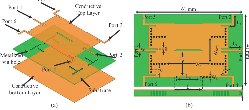
Figure 1 shows structure of the proposed component which is printed on a layer of Rogers 4003 substrate with relative permittivity of (εr =)3.55, loss tangent of (tanδ =)0.0027, and substrate thickness of (h = 20 mil) 0.508 mm. It is composed of two HMSIW couplers placed side by side. Details about the proposed HMSIW couplers are referred to in [6]. However, the coupling region of the proposed HMSIW coupler is modified, and it is thinner than that in [6] to attain low values ofS11 and S14. The thinner region leads to an increase in −3 dB bandwidth. Narrowing down the coupling area prevents higher modes excitation. In order to attain a 50 Ω input impedance, a microstrip feed line with width of Wf = 1.1 mm is used. On account of impedance matching between microstrip and HMSIW feed line (microstrip-to-HMSIW transition), a semi grounded coplanar waveguide is located at the end of microstrip feed line. The total dimension of the component is 41×61 mm2. Other values of component parameters are: WSIW = 15, Ws= 0.5,Wc = 25.5,Lc = 14, Ls = 16,Ls1= 13, Lf = 8, s= 1, d= 1.5 (all values are in mm).
Por t 1
Port 2 Port 3
Por t 4 Por t 6
Port 5
Cond uctive Top Layer
Cond uctive
bottom Layer Substrate
Metalized via hole Lf Lf Wf Wc Lc Ls1 Ls Ws g s d h 61 mm 41 m m Po rt 1 Po rt 2 Port 3 Port 4 Port 5 Port 6 W SI W (a) (b)
Figure 1. Structure of the proposed six port microwave component. (a) perspective view and (b) top view.
3. RESULT AND DISCUSSION 3.1. HMSIW Transient
The proposed component is simulated and optimized by using High Frequency Structure Simulator (HFSS) ver. 13. One of the most important sections in designing HMSIW structure is implementation transient between microstrip line and HMSIW structure. In this structure, a novel method is used to perform the transient. As displayed in Fig. 2, in order to achieve impedance matching between microstrip feed line and HMSIW structure, a matching slot which plays the role of a load regulator is used. Parametric study of the changing slot dimension is displayed in Fig. 3. By increasing slot length
L
tg
tPort 1
Po
rt
2
Figure 2. Configuration of transient between HMSIW and microstrip feed line.
8 9 10 11 12 13 14
Frequency (GHz) -50
Figure 3. Parametric study of scattering parameters of transient.
-j1.0
Figure 4. Parametric study of impedance matching curve by changingLt.
3.2. HMSIW 90-Degree Coupler
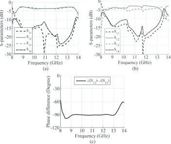
Configuration of the proposed HMSIW coupler is presented in Fig. 5. The structure of the coupler is derived from [6]. However, the proposed coupler has an advantage over [6], and it is the creation of a narrow coupling region to prevent higher order modes. Obtained results for simulated magnitude of 90◦ HMSIW coupler in two states with and without narrowing coupling region are indicated in Figs. 6(a) and (b), respectively. As aforementioned, by modifying coupling region we make an improvement of
Top conductor
bottom
conductor Substrate
Port 3 Port 4
Port 2 Port 1
Coupling Region
(a) (b)
Figure 5. Structure of the proposed HMSIW 90-degree coupler. (a) perspective view and (b) top view.
(a) (b)
(c)
Figure 6. (a) The simulated magnitude of HMSIW coupler with narrowing region; (b) The simulated magnitude of HMSIW coupler without narrowing region; And (c) the phase shifting of HMSIW 90-degree coupler with narrowing region.
3.3. Proposed Multi-Functional 6 Ports Component
Port 1
Port 2
Port 3
Port 4
Figure 7. The E-field distribution of HMSIW 90-degree coupler.
Por
t
1
Po
rt
2
Por
t
3
Po
rt
4
Por
t
5
Po
rt
6
Figure 8. E-field distribution of proposed multi-functional 6-port component.
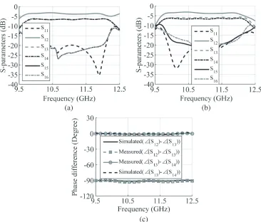
Meanwhile, phase shifting between ports 2–3 and 2–4 is 90 degrees, and in this condition, ports 5 and 6 are isolated ports. When port 5 of the proposed component is excited, it acts as a −3 dB/90-degree equal divider coupler with output ports 3 (directed port) and 2 (coupled port), and another port is isolated port. As the proposed component is a symmetrical structure, by stimulating each of ports 3, 4, and 6, the results of port 5 will be shown, and results of each of ports 1 and 2, when one of them is input port and other ports are output ports, will be the same. To prove the veracity of what was said, the E-field distribution, when port 1 is input port and other ports are output ports, is shown in Fig. 8. The proposed component is measured by Agilent vector network analyser (VNA) 8722ES. The comparison between simulated and measured magnitude and phase scattering parameters of the suggested component for each of ports 1 and 5 are indicated in Fig. 9 and Fig. 10, respectively. In
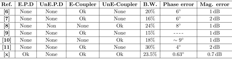
Table 1. A Comparison between the functionality of the proposed works with those of some recently reported works; E.P.D is equal power divider, UnE.P.D is unequal power divider, E-Coupler is equal coupler, UnE-Coupler is unequal coupler, and [x] is this work.
Ref. E.P.D UnE.P.D E-Coupler UnE-Coupler B.W. Phase error Mag. error
[6] None None Ok None 20% 6◦ 1 dB
[7] None None Ok None 16% 6◦ 2 dB
[8] None Non None Ok 24% 8◦ 1 dB
[9] None None Ok None 15% - - - - 1 dB
[10] None None None Ok 18% ∼9◦ 1 dB
[11] None None Ok None 30% 4◦ 2 dB
(a) (b)
(c)
Figure 9. The comparison between simulated and measured magnitudes and phase of S-parameters for input port 1; (a) Simulated magnitude, (b) measured magnitude, and (c) simulated and measured phase difference.
Fig. 9, two unequal (−3 and−6 dB) 90-degree coupler for ports 2–3 and 2–4 and an equal−6 dB power divider for ports 3–4 in frequency range from 9.68 to 12.26 GHz are proved. As seen in Fig. 9, simulated and measured results have good agreement. In Fig. 10, a comparison between simulated and measured results, when port 5 is input port, is illustrated. As indicated by the figure, ports 3 to 6 behave as a 90-degree coupler in frequency range from 10.03 to 12.28 GHz. Therefore, by selecting each of the ports as an input port and other ports as output ports, the structure can behave as a microwave component such as equal and unequal power divider and 90-degree coupler.
Table 1 depicts the performance comparison between the proposed structures and some other
(c)
Figure 10. The comparison between simulated and measured magnitudes and phase of S-parameters for input port 5; (a) Simulated magnitude, (b) measured magnitude, and (c) simulated and measured phase difference.
Figure 11. The photograph of a sample of the proposed fabricated structure.
works recently reported in the literature. It is demonstrated that the proposed SIW component is more manoeuvrable and has wider bandwidth than other works reported in recent years. In fact, we can provide an integrated component which, by changing input and output ports, can attain a microwave component such as equal and unequal power divider and coupler in −3 dB and −6 dB states. Compared with some works such as [11], the proposed structure has narrow BW, can play some microwave component roles and has lower phase error than [11].
A photograph of a sample of the proposed fabricated multi-functional six-port microwave component is illustrated in Fig. 11.
4. CONCLUSION
1. Wu, K., D. Deslandes, and Y. Cassivi, “The substrate integratedcircuits a new concept for high-frequency electronics and optoelectronics,” Proc. 6th Int. Conf. Telecommun. Modern Sat., Cable Broadcasting Service (TELSIKS), PIII–PX, 2003.
2. Sakakibara, Y. K., A. Akiyama, J. Hirokawa, M. Ando, and N. Goto, “Alternating phase-fed waveguide slot arrays with a single-layer multiple-way power divider,” Proc. Inst. Elect. Eng., Vol. 144, 425–430, 1997.
3. Zeid, A. and H. Baudrand, “Electromagnetic scattering by metallic holes and its applications in microwave circuit design,” IEEE Trans. Microw. Theory Tech., Vol. 50, No. 4, 1198–1206, Apr. 2002.
4. Hong, W., B. Liu, Y. Q. Wang, Q. H. Lai, and K. Wu, “Half mode substrate integrated waveguide: A new guided wave structure for microwave and millimeter wave application,”Proc. Joint 31st Int. Conf. Infrared Millim. Waves 14th Int. Conf. Terahertz Electron., 219, Shanghai, China, Sep. 18– 22, 2006.
5. Christopher, S. and V. A. Abid Hussain, “Design aspects of compact high power multiport unequal power dividers,”IEEE International Symposium on Phased Array Systems and Technology, 1996, 63–67, Oct. 15–18, 1996.
6. Liu, B., W. Hong, Y. Q. Wang, Q. H. Lai, and K. Wu, “Half Mode Substrate Integrated Waveguide (HMSIW) 3-dB coupler,”IEEE Microwave and Wireless Components Letters, Vol. 17, No. 1, 22–24, Jan. 2007.
7. Ali, A., H. Aubert, N. Fonseca, and F. Coccetti, “Wideband two-layer SIW coupler: Design and experiment,” Electronics Letters, Vol. 45, No. 13, 687–689, Jun. 18, 2009.
8. Ali, A. A. M., H. B. El-Shaarawy, and H. Aubert, “Compact wideband double-layer half-mode substrate integrated waveguide 90◦ deg coupler,” Electronics Letters, Vol. 47, No. 10, 598–599, May 12, 2011.
9. Djerafi, T., K. Wu, and S. O. Tatu, “3 dB 90◦ hybrid quasi-optical coupler with air field slab in SIW technology,” IEEE Microwave and Wireless Components Letters, Vol. 24, No. 4, 221–223, Apr. 2014.