Second-Order Mixed Coupling Filter with One Controllable
Transmission Zero Using Multilayer Substrate Integrated Waveguide
Tao Zhang, Hong-Wei Deng*, Fei Liu, and Tao Xu
Abstract—In this letter, a compact second-order mixed coupling bandpass filter (BPF) with one controllable transmission zero (TZ) near the passband edge is presented using multilayer substrate integrated waveguide (SIW). Two arranged circular SIW resonators can be vertically coupled via the circular apertures etched on the middle metal layer while preserving a compact physical size compared with the conventional horizontally coupled filter made of the single layer. The mixed electric and magnetic coupling can be introduced by two etched circular apertures. And one controllable TZ can be created in the lower stopband for the magnetic-dominant or in the upper stopband for the electric-dominant. To demonstrate the proposed design method, a multilayer SIW BPF for WLAN application has been designed and fabricated, and the measured results show good agreement with the simulated ones.
1. INTRODUCTION
SIW filters, which are generally synthesized in a planar substrate with arrays of metallic vias and widely used in various communication systems, can provide a low-profile, easy integration and low-cost solution while maintaining high-quality factor, high power capability performance as conventional metal waveguide filters [1, 2]. SIW filters with multiple TZs are required to meet the increasing demands of modern communication systems with regard to compact size and high selectivity [3, 4]. Therefore, they have been extensively investigated and various design approaches using the printed circuit board (PCB) or low-temperature co-fired ceramic (LTCC) processes have been proposed. In [5, 6], the implementation of the mixed electric and magnetic coupling SIW filters with TZs for high selectivity have been reported, in which an inductive window between two SIW resonators introduces the magnetic coupling, and an embedded short-ended strip is employed to create the electric coupling, however, this filter is relatively large not only because of its planar arranging structure, but also due to suffering from the structure complexity and lack of flexibility, and there will be radiation loss if it operated in millimeter-wave bands. The application of SIW technology makes the realization of filters with the multilayer structure and compact size possible in [7–12]. The coupling between the vertically stacked SIW resonators can be introduced by etching the apertures with different sizes, positions and number on the middle metal layer. And the vertically oriented coupling also plays a role in achieving the cross coupling. The mixed coupling is realized by embedding apertures on the inductive window between the horizontally oriented cascade SIW resonators of the single layer. Hence, the high selectivity for the multilayer SIW filters are achieved in [11, 12]. However, the filter which directly introduces mixed coupling by etching appropriate aperture structures between two vertically stacked SIW resonators has rarely been reported.
In this letter, a compact SIW filter is developed with two circular SIW resonators which are fed by 50 Ω microstrip line and two slotlines, and allocated integration in the vertical direction, as illustrated
Received 3 May 2017, Accepted 14 June 2017, Scheduled 30 June 2017
* Corresponding author: Hong-Wei Deng ([email protected]).
Metal layer-1
Metal layer-2 Substrate Middle Metal layer
Metal layer-2 Metal layer-1 Middle
metal layer
r L
R
Via-hole
l1
l2
W
ls (a)
(b)
Figure 1. Schematics of the vertically coupled multilayer second-order filter. (a) Cross view; (b) Geometric configuration.
in Fig. 1. Based on the analysis of the electromagnetic field distributions of the circular SIW resonator, the mixed coupling can be introduced by two circular apertures etched in the middle metal layer to generate a controllable TZ. When mixed coupling becomes electric-dominant, the TZ is generated in the upper stopband, inversely, the TZ is then allocated on the lower stopband. Moreover, the embedded mixed coupling form makes it have little influence from the outside. A compact second-order mixed coupling filter has been designed, fabricated and measured. The simulated results are in good agreement with the measured ones.
2. PROPOSED MULTILAYER SECOND-ORDER MIXED COUPLING FILTER WITH ONE TZ
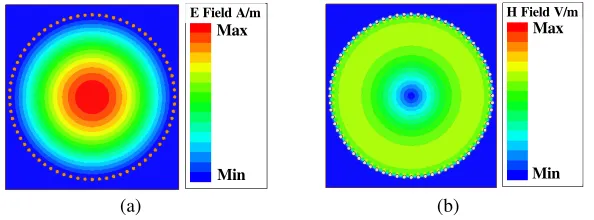
For the circular SIW resonator, the electric field is vertically polarized, and the magnetic field is circular within the cavity [13]. The fundamental mode is TM010 mode, and the resonant frequency f01 can be
calculated by:
fmn= μmn·c
2πR√μrεr (1)
where fmn is the resonant frequency of the TMmn0 mode, μmn the corresponding zero of the Bessel
function (m and n are non-negative integers), c the light velocity in free space, R the radius of the circular SIW resonator, and εr and μr are the relative dielectric constant and permeability of the substrate, respectively. The resonant frequencyf11 of the first higher-order modeTM110 occurs at the
1.6f01. Fig. 2 shows the simulated field distributions of the TM010 in the circular SIW resonator. It
can be seen that the maximum electric and magnetic fields are generated at the center and the fringe of the circular SIW resonator, respectively.
E Field A/m
Min Max
H Field V/m
Min Max
(a) (b)
Figure 2. Simulated electromagnetic field distributions of the TM010. (a) Electric field distribution;
Hence, employing circular SIW resonator, the vertically coupled multilayer structure is implemented while the aperture is placed at the middle metal layer. When the aperture is located at the center of the middle metal layer, there exist maximum electric coupling and minimum magnetic coupling. And the situation is inverse when the aperture is located at the fringe. As the aperture continuously moves from the center to fringe of the resonator, the electric coupling is gradually weakened, and the magnetic coupling starts to strengthen, otherwise, the reverse. Through the designed coupled structure, the relative proportion of the electric and magnetic couplings can be adjusted flexibly to realize the mixed coupling. The substrate used herein is RT/Duriod 4003 with a thickness of 0.508 mm, permittivity of 3.38 and loss tangent of 0.0027.
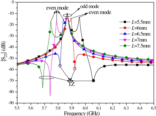
To strengthen the coupling between two SIW resonators, the coupling structure in Fig. 1(b) is adopted with two same circular apertures with radius r and distance L. Fig. 3 shows the simulated resonator responses of the coupled structure with different L under the constant r under the weakly coupled. When the L increases, the odd- and even-modes split and one TZ appears in the finite frequency, both the even-mode frequency and TZ shift to the left, whereas the odd-mode frequency does little change. The TZ is on the high side of the two modes when the even-mode frequency is higher than the odd-mode frequency. Inversely, the TZ is on the low side of the two modes. Thus, it can be observed from Fig. 3 that the TZ appears to be closely associated with the even mode, and this property can be explored for designing mixed coupling filters with an asymmetrical frequency response.
5.5 5.6 5.7 5.8 5.9 6.0 6.1 6.2 6.3 6.4 6.5 -90
-80 -70 -60 -50 -40 -30 -20 -10 0
TZ
even mode even mode odd mode
|S21
| (
dB
)
Frequency (GHz)
L=5.5mm L=6mm L=6.5mm L=7mm L=7.5mm
Figure 3. Simulated resonant mode splitting phenomena by changing theL with r = 2.5 mm under the weakly coupled by Ansoft HFSS 13.0.
Based on the extracted odd- and even-frequencies, the electric coupling coefficient Ec, magnetic
coupling coefficientMc, and the total coupling coefficientkacan be obtained by the proposed procedures
and Equations (14)–(15) in [7]. It is obvious that the changes of the odd mode and transmission zero frequencies lead to the changes ofEc and Mc. The ratio ofEc/Mc decreases with the increases of theL, whereas ka increases. By properly designing the sizes and position of the coupling circular apertures, the desired values of electric and magnetic coupling can be obtained.
The mixed coupling multilayer SIW filter based on the above-described coupling structure is designed, which has a TZ of fm = 5.9 GHz, central frequency of f = 5.8 GHz with 1% 3 dB FBW, respectively. For the desired second-order BPF, the corresponding external quality factor Qe and ka
can be calculated as [15]: Qe = 66.48 andka =−0.0047. Considering the location of TZ, the ratio of Ec/Mc = 1.034 can be calculated from [8]:
ka= (Mc−Ec)/(1−Mc·Ec) f0/fm=
Mc/Ec (2)
Hence,Landrcan be determined according to the extracted ratio ofEc/Mc andkavalues against
5.0 5.2 5.4 5.6 5.8 6.0 6.2 6.4 6.6 6.8 7.0 7.2 7.4 7.6 7.8 8.0 8.2 8.4 0.94 0.96 0.98 1.00 1.02 1.04 1.06 1.08 1.10 Ec / Mc
Distance L (mm)
r=2mm r=2.5mm r=3mm r=3.5mm -0.08 -0.06 -0.04 -0.02 0.00 0.02 0.04 0.06 0.08 0.10 0.12 0.14 0.16 0.18 0.20 T ota l c ou plin g c oe ffic ie nt k a
Figure 4. The ratio ofEc/Mc and total coupling coefficient ka against Lfor variousr.
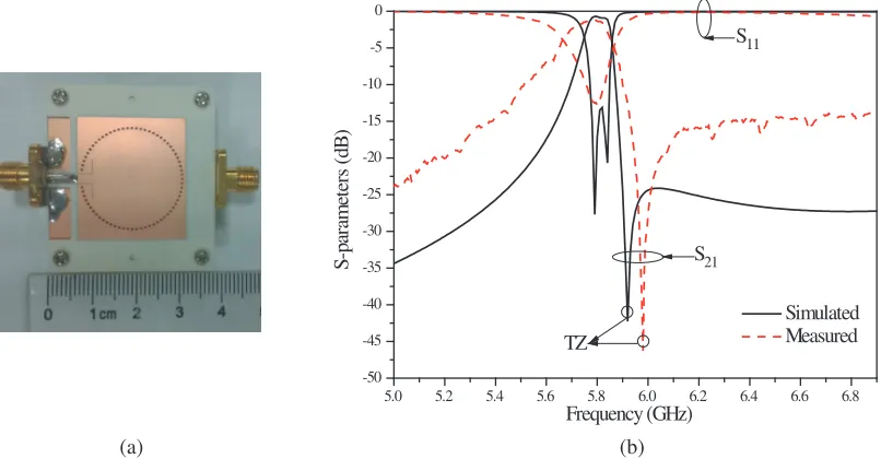
5.0 5.2 5.4 5.6 5.8 6.0 6.2 6.4 6.6 6.8
-50 -45 -40 -35 -30 -25 -20 -15 -10 -5 0 S21 S11 TZ Simulated Measured S -p ara m et ers (d B ) Frequency (GHz) (a) (b)
Figure 5. Photograph, simulation and measured results of designed second-order multilayer filter. (a) Photograph; (b) Simulated and measured frequency responses.
The Qe can be numerically estimated by the varying dimensions of L-shape slotlines of a singly fed
resonator [15]. The filter is optimized by Ansoft HFSS 13.0 and the dimensions are determined as:
W = 1.588 mm, l1 = 3 mm, l2 = 3.05 mm, ls = 0.15 mm, R = 13.35 mm, r = 2.5 mm, L = 6 mm,
R via-hole = 0.3 mm,h thickness = 0.508 mm.
3. EXPERIMENTAL RESULTS
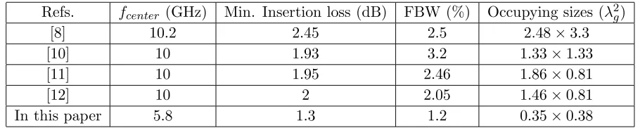
Table 1. Comparisons with some other SIW filters.
Refs. fcenter (GHz) Min. Insertion loss (dB) FBW (%) Occupying sizes (λ2g)
[8] 10.2 2.45 2.5 2.48×3.3
[10] 10 1.93 3.2 1.33×1.33
[11] 10 1.95 2.46 1.86×0.81
[12] 10 2 2.05 1.46×0.81
In this paper 5.8 1.3 1.2 0.35×0.38
well as the fabrication tolerance in the etching process.
Table 1 shows the comparison with some other recent works on SIW filters. As can be seen, the proposed filter not only sharps the upper skirt owing to the mixed coupling with one controllable TZ, but also has a compact size by profiting from multilayer structure.
4. CONCLUSION
In this letter, based on the analysis of the fundamental mode of the SIW resonator, a compact second-order mixed coupling SIW filter with one controllable TZ is realized by designing coupled structure in the middle metal layer. The design schematic can be extended to the filter with multiple vertically stacked SIW resonators.
ACKNOWLEDGMENT
This work was supported by the National Natural Science Foundation (NSF) of China under Grant 61501232, by the Postdoctoral Science Foundation of China under Grant 2015M571749, by the State Key Laboratory of Millimeter Waves of K201716, and by the Fundamental Research Funds for the Central Universities.
REFERENCES
1. Wu, K., D. Deslandes, and Y. Cassivi, “The substrate integrated circuits – a new concept for high-frequency electronics and optoelectronics,” 6th Int. Conf. on Telecommunications in Modem Satellite, Cable and Broadcasting Service, (TELSIKS 2003), Vol. 1, 3–5, Nis, Serbia and Montenegro, 2003.
2. Deslandes, D. and K. Wu, “Single-substrate integration techniques for planar circuits and waveguide filter,” IEEE Trans. Microw. Theory Tech., Vol. 51, No. 2, 593–596, 2003.
3. Li, R.-Q., X.-H. Tang, and F. Xiao, “Design of substrate integrated waveguide transversal filter with high selectivity,” IEEE Microw. Wirel. Compon. Lett., Vol. 20, No. 6, 328–330, 2010.
4. Chen, X.-P., K. Wu, and D. Drolet, “Substrate integrated waveguide flter with improved stopband performance for satellite ground terminal,” IEEE Trans. Microw. Theory Tech., Vol. 57, No. 3, 674–683, 2009.
5. Shen, W., L.-S. Wu, X.-W. Sun, W.-Y. Yin, and J.-F. Mao, “Novel Substrate Integrated Waveguide Filters with Mixed Cross Coupling (MCC),”IEEE Microw. Wirel. Compon. Lett., Vol. 19, No. 11, 701–703, 2009.
6. Gong, K., W. Hong, Y. Zhang, P. Chen, and C.-J. You, “Substrate integrated waveguide quasi-elliptic filters with controllable electric and magnetic mixed coupling,”IEEE Trans. Microw. Theory Tech., Vol. 60, No. 10, 3071–3078, 2012.
8. Chen, J. X., W. Hong, X. P. Chen, P. P. Yan, Q.-H. Lai, and K. Wu, “An LTCC X-band receiver front-end using embedded multilayer substrate integrated waveguide filter,”Microw. Opt. Technol. Lett., Vol. 50, No. 2, 285–287, 2008.
9. Wei, Q.-F., Z.-F. Li, L. Li, W.-J. Zhang, and J.-F. Mao, “Three-pole crosscoupled substrate-integrated waveguide bandpass filters based on PCB process and multilayer LTCC technology,” Microw. Opt. Technol. Lett., Vol. 51, No. 1, 71–73, 2009.
10. Xu, Z.-Q. and H. Xia, “Miniaturized multilayer dual-mode substrate integrated waveguide filter with multiple transmission zeros,” Progress In Electromagnetics Research, Vol. 139, 627–642, 2013. 11. Xu, Z.-Q., P. Wang, J.-X. Liao, and Y. Shi, “Substrate integrated waveguide filter with mixed
coupled modified trisections,” Electron. Lett., Vol. 49, No. 7, 482–483, 2013.
12. Xu, Z.-Q., P.-Wang, K.-W. Qian, and Z. Tian, “Substrate integrated waveguide filter with embedded mixed source–load coupling,”Electron. Lett., Vol. 49, No. 23, 1464–1465, 2013.
13. Potelon, B., J.-F. Favennec, C. Quendo, E. Rius, C. Person, and J.-C. Bohorquez, “Design of a substrate integrated waveguide (SIW) filter using a novel topology of coupling,” IEEE Microw. Wirel. Compon. Lett., Vol. 18, No. 9, 596–598, 2008.
14. Chu, Q.-X. and H. Wang, “A compact open-loop filter with mixed electric and magnetic coupling,” IEEE Trans. Microw. Theory Tech., Vol. 56, No. 2, 431–4398, 2008.