Omega-shaped Geometries of Reflectarray Resonant Elements with
Low Cross-polarization for Wideband and Dual-Polarization Use
Daichi Higashi*, Hiroyuki Deguchi, and Mikio Tsuji
Abstract—This paper presents low cross-polarization single-layer reflectarray elements for dual-polarization use. These elements have an omega-shaped symmetrical structure to realize the cross-polarization reduction and also provide parallel linear reflection-phase properties with almost the same slop characteristics for the frequency, thereby achieving the desirable reflection phase range more than
360◦ over the wide frequency range. To verify effectiveness of the proposed elements, a reflectarray
antenna with an offset feed is constructed by them, and wideband frequency characteristics are also confirmed at Ku-band numerically and experimentally.
1. INTRODUCTION
A reflectarray are composed of many reflecting elements printed on a conductor-backed dielectric substrate [1]. So, it has a low-profile, thin, and flat structure and also simple feed system, compared with conventional parabolic reflectors. The phase distribution on its aperture is controlled by arranging various resonant elements with different resonant frequency, thereby changing the reflecting direction. In recent years, reflectarrays have been applied to a lot of applications such as deployable reflector antennas [2], millimeter-wave imaging systems [3] and FSR(frequency selective reflector) to eliminate blind area [4]. In general, wideband, dual-polarization and low cross-polarization properties are required for a reflectarray. However, it has a major drawback which is narrow bandwidth operation because the reflection-phase property of each element based on resonance greatly depends on the frequency. To improve the antenna bandwidth in reflectarray, linearization of reflection phase response for the frequency can be realized in some investigation by using thick substrate [5], double square-rings [6], stacked patches [7], multi-resonant elements with low-cross polarization [8], phase-delay lines [9] and so on. We have also reported in [10–14] to improve the bandwidth based on multi-resonant behavior for single- and dual-polarization use. The elements proposed in [14] have broadband property, but cause
high-level cross-polarization (more than about −10 dB) over the wide frequency range. Therefore, it is
necessary to suppress cross polarization, while keeping wide-band co-polarization properties. Therefore, this paper presents new reflectarray elements to suppress cross polarization [15]. These elements have
linear phase lines and the desirable reflection-phase range of 360◦ for the frequency response. To show
effectiveness of the proposed elements, a Ku-band reflectarray antenna is constructed by them and is evaluated by comparison of the radiation patterns between the calculated and the measured results.
2. ANALYTICAL METHOD
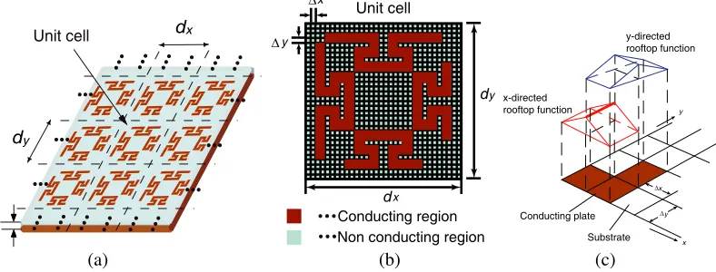
Figure 1(a) shows periodic reflectarray elements. Assuming an infinite periodic array, the reflection phase for an incident plane wave can be calculated by the method of moments (MoM) based on the
Received 18 October 2017, Accepted 10 January 2018, Scheduled 18 January 2018
* Corresponding author: Daichi Higashi ([email protected]).
spectral domain Green’s function with periodical boundary condition [16,17]. Fig. 1(b) shows a unit cell
(dx×dy) divided into sub-cells (Δx×Δy), and Fig. 1(c) shows the roof-top sub-domain basis function
expanding unknown current distributions on the conductor strip element in thex and the y directions.
The simultaneous linear equations in the MoM are formulated by using FFT and are solved by the conjugate gradient method (CGM). The scattered electric field from the reflectarray that is derived by enforcing Floquet’s periodicity condition can be expressed as follows:
Ex(s)(x, y)
Ey(s)(x, y)
=
∞
p=−∞ ∞
q=−∞
˜
Gxx G˜xy
˜
Gyx G˜yy
·
˜
Jx(kxp, kyq)
˜
Jy(kxp, kyq)
ejkxpxejkyqy
where Ex(s) and Ey(s) represent the x and the y components of the scattered electric field, respectively.
The transformed derivatives, the dyadic spectral Green’s function and their constants are incorporated
into ˜Gxx, ˜Gxy, ˜Gyx and ˜Gyy to simplify the notation. k0 is the wave number in the free space, and
also kxp and kyq can be expressed as kxp = k0sinθcosφ+ 2πp/dx and kyq = k0sinθsinφ+ 2πq/dy,
respectively. The indices (p, q) represents Floquet’s harmonics. ˜Jx and ˜Jy are the Fourier transforms
of the x component Jx and they component Jy of the unknown currents, respectively. Applying the
boundary condition E(i)+E(s) = 0 on the conductor plates, we can solve unknown currents by using
Galerkin’s procedure for the currents Jx and Jy expanded in terms of the roof-top basis functions as
shown in Fig. 1(c).
Unit cell dx
dy
h
(a)
Unit cell
y x
dx
dy
Conducting region Non conducting region
(b)
x
x y
y x-directed
rooftop function
Conducting plate
Substrate y-directed rooftop function
(c)
Δ
Δ
Δ
Δ
Figure 1. Analysis model for MoM. (a) Periodic reflectarray elements. (b) Unit cell. (c) Roof-top basis function.
3. INVESTIGATION OF REFLECTARRAY ELEMENTS 3.1. Proposed Elements
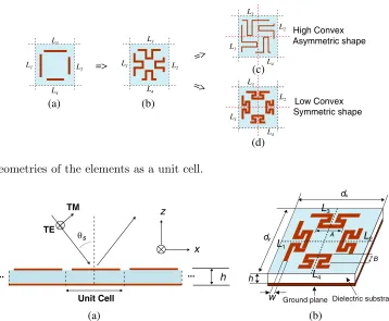
Figure 2 shows geometries of the element’s shape developed by the authors for dual-polarization and wide-band reflectarray [13–15]. To realize the dual-polarization use, the additional two resonant elements are put at the perpendicular as shown in Fig. 2(a). Then, the four resonant elements are modified convexly to achieve wideband property as shown in Fig. 2(b). When longer element’s length is needed, the adjacent elements contact with each other. To avoid such a contact, we modified convex part as shown in Fig. 2(c), so that this type of element shape make it possible to extend the wider frequency range. However, these elements generate un-negligible cross-polarized component because of asymmetric element’s arrangement. So, it is necessary to lower the height of convex part. As a result, the convex part is modified into an Omega-shape with symmetrical structure as shown in Fig. 2(d). The dimensions at
the center frequency 15 GHz are as follows, the periodic of a unit celldx=dy = 9.6 [mm], the thickness
of supported dielectric substrate h= 3.0 [mm] with relative permittivity 1.68 (tanδ= 0.001), the strip
width of the elements w = 0.6 [mm], and the degree of convex B = 1.8 [mm]. Analytical model to
(a) (b)
(d) L2
L1
L3
L4
L2
L1
L3
L4
(c) L2
L1
L3
L4
L2
L1
L3
L4
High Convex
Low Convex Asymmetric shape
Symmetric shape
=> =>
=>
Figure 2. Geometries of the elements as a unit cell.
Unit Cell
θs TE
TM z
x
h
(a)
h
w
A
Ground plane Dielectric substrate
dx
dy
L1 L2
L4 L3
B
(b)
... ...
Figure 3. Analysis parameters for MoM. (a) Definition of coordinate system. (b) Structure of proposed element.
dielectric loss and the conductor loss are not included in the reflection phase analysis because of the
losses are less than about 0.1 dB. A unit cell is divided into sub-cells (32×32) in the MoM analysis,
and also the number of Floquet modes is 192 in the x and y directions.
3.2. Combination of the Element’s Lengths
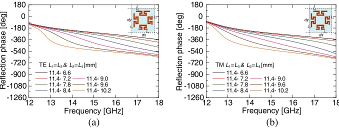
To realize broadband property, reflecting elements are required to provide the linear phase slope for
the frequency. So, we have investigated the phase property for various element lengths L1(=L3) and
L2(=L4). Figs. 4(a) and (b) shows the reflection phase response for the TE and the TM incidences on
various combinations between lengths ofL2 andL4. We can see from this figure that the phases for both
the incidences have almost linear property for combination of the element’s lengths L1(= L3) = 11.4
[mm] andL2(=L4) = 8.4 [mm]. Hereafter, we fix difference of the length L1(=L3)−L2(=L4) to be
3.0 mm without depending on the length L1(=L3).
3.3. Characteristics of Proposed Elements
Figure 5 shows the geometries for constructing a reflectarray antenna. Their reflection phase properties for the TE and the TM incidences are shown in Figs. 6(a) and (b), respectively. It is clear from this figure that the phases have the linear properties with almost the same slope, and also provide phase-shift
range 360◦ over the wide frequency range. Fig. 7 shows the reflection phase properties of the element
#1 and #12 for the different incident angles of the TE and the TM incidences. The phase curves are
almost the same for the incident angle less than 50◦. Figs. 8(a) and (b) shows the amplitude properties
Frequency [GHz]
Reflection phase [deg]
-1260 -1080 -900 -720 -540 -360 -180 0 180 L2 L1 L3 L4 dx dy
TE L1=L3 & L2=L4 [mm]
11.4- 6.6
11.4- 7.2 11.4- 9.0 11.4- 7.8 11.4- 9.6 11.4- 8.4 11.4- 10.2
12 13 14 15 16 17 18
(a) -1260 -1080 -900 -720 -540 -360 -180 0 180 L2 L1 L3 L4 dx dy
TM L1=L3 & L2=L4 [mm]
11.4- 6.6
11.4- 7.2 11.4- 9.0 11.4- 7.8 11.4- 9.6 11.4- 8.4 11.4- 10.2
12 13 14 15 16 17 18
(b)
Frequency [GHz]
Reflection phase [deg]
Figure 4. Combination of the element’s lengths betweenL1(= L3) and L2(= L4). (a) TE incidence. (b) TM incidence.
Figure 5. Geometries for the reflectarray design.
L2 L1 L3 L4 dx dy
TEL1=L3 & L2=L4 [mm]
10.2- 7.2 12.9- 9.9 10.8- 7.8 13.2- 10.2 11.1- 8.1 13.5- 10.5 11.4- 8.4 14.1- 11.1 12.0- 9.0 14.7- 11.7 12.3- 9.3 15.3-12.3 -1260 -1080 -900 -720 -540 -360 -180 0 180
12 13 14 15 16 17 18
(a) L2 L1 L3 L4 dx dy
TML1=L3 & L2=L4 [mm]
10.2- 7.2 12.9- 9.9 10.8- 7.8 13.2- 10.2 11.1- 8.1 13.5- 10.5 11.4- 8.4 14.1- 11.1 12.0- 9.0 14.7- 11.7 12.3- 9.3 15.3-12.3 -1260 -1080 -900 -720 -540 -360 -180 0 180
12 13 14 15 16 17 18
(b)
Frequency [GHz]
Reflection phase [deg]
Frequency [GHz]
Reflection phase [deg]
Figure 6. Frequency responses of the reflection phase for the TE and the TM incidences. (a) TE incidence. (b) TM incidence.
12 13 14 15 16 17 18
-1260 -1080 -900 -720 -540 -360 -180 0 180
geometry1 (solid line)
0 degree 30 degree 50 degree
geometry12 (dashed line)
0 degree 30 degree 50 degree 70 degree 70 degree (a)
12 13 14 15 16 17 18
-1260 -1080 -900 -720 -540 -360 -180 0 180
geometry1 (solid line)
0 degree 30 degree 50 degree
geom etry12 (dashed line)
0 d egree 30 degree 50 degree 70 degree 70 degree (b) Frequency [GHz]
Reflection phase [deg]
Frequency [GHz]
Reflection phase [deg]
TE L1=L3, L2=L4 [mm]
10.2- 7.2 10.8- 7.8 11.1- 8.1 11.4- 8.4
12.9- 9.9 13.2- 10.2 12.0- 9.0 12.3- 9.3
13.5- 10.5 14.1- 11.1 14.7- 11.7 15.3-12.3
-20 -15 -10 -5 0
Frequency[GHz]
Cross polarization[dB]
12 13 14 15 16 17 18
(a)
TM L1=L3, L2=L4 [mm]
10.2- 7.2 10.8- 7.8 11.1- 8.1 11.4- 8.4
12.9- 9.9 13.2- 10.2 12.0- 9.0 12.3- 9.3
13.5- 10.5 14.1- 11.1 14.7- 11.7 15.3-12.3
-20 -15 -10 -5 0
Frequency[GHz]
Cross polarization[dB]
12 13 14 15 16 17 18
(b)
Figure 8. Cross-polarization level for the TE and the TM incidences. (a) TE incidence. (b) TM incidence.
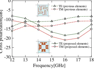
TE (previous elements) TM (previous elements)
TE (proposed elements) TM (proposed elements)
Frequency[GHz]
Cross polarization[dB]
-30 -25 -20 -15 -10 -5 0
12 13 14 15 16 17 18
Figure 9. Comparison of the average of cross-polarization level for the TE and the TM incidences.
4. REFLECTARRAY DESIGN 4.1. Design Example
We now design an offset feed reflectarray with square aperture of dimension 153.6 mm × 153.6 mm
(256 cells) constructed by the proposed elements (#1–#12) at the Ku-band. The arrangement of the
reflectarray antenna is shown in Fig. 10. The degradation of its gain keeps less than 0.35 dB in the
y
x
z 153.6 mm
153.6 mm
Phase center
Feed horn
s= 30 h= 3.0 mm
= 30
Rs
= 260 mm
θi-th
θ
Θ
case of the reflectarray elements having the phase of 30◦ interval [18]. In linear array design, it is often treated as an optimization problem of the minimizing number of elements by using compressive-sensing algorithm [19]. However, we didn’t deal with the problem of minimizing the number of elements by the sparse array layout because our analysis is based on the periodic array. An offset angle of a primary
illuminater is θs = 30◦ and the reflected angle Θ = 30◦ (x-z plane). The distance between its phase
center and the center of the reflectarray is chosen to be 260 mm and the edge level on the reflectarray
is −15 dB. For the offset feed at θs = 30◦, the angle incident to the element takes the range from 7◦
to 47◦. As a result, we design all elements to have the desired phase properties corresponding to the
incident angle.
5. NUMERICAL AND EXPERIMENTAL EVALUATION
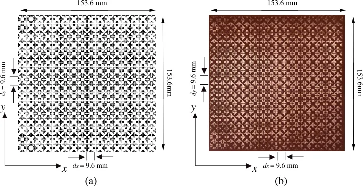
Figures 11(a) and (b) show the top view of the designed reflectarray antenna and the fabricated
reflectarraay antenna, respectively. The copper strips with thickness 18µm are photo-etched on a thin
dielectric film (Polyimide) with thickness 125µm and the interval between the film and the ground plane
is kept constant by a polyfoam (dielectric constantr= 1.68) with thicknessh= 3.0 [mm]. Fig. 12 shows
comparison of the radiation patterns between the calculated and the measured results for the TE and the TM incident waves at 14 GHz, 15 GHz and 18 GHz. The calculated far-field patterns are obtained by using the aperture field method [20]. It is clear from these figures that the main-beam patterns for both the incident waves agree well with each other. Moreover, the measured cross-polarization level
for the main-beam is almost suppressed less than about −15 dB. Figs. 13 and 14 show comparison
of the gain and the aperture efficiency between the calculated and the measured values, respectively. The calculated and the measured gains at the center frequency 15 GHz are 26.1 dB and 25.8 dB for the TE incidence, and 26.1 dB and 25.3 dB for the TM incidence, respectively. And aperture efficiencies are 54.7% and 51.4% for the TE incidence, and 54.7% and 46.1% for the TM incidence, respectively. Fig. 15 shows comparison of the measured cross-polarization level normalized by peak gain between the previously proposed elements [14] and the proposed ones. We can see that the previous shape generates
the un-negligible cross-polarization component more than −10 dB because the height of the element’s
convex is too high, while the proposed elements have low cross-polarization property over the wide frequency range. These results verify that the Omega-shaped elements presented here are useful for wideband use with both dual-polarization and low cross-polarization properties.
y
x
d
y
= 9.6 mm
dx = 9.6 mm
153.6 mm
153.6m
m
(a)
y
x
d
y
= 9.6 mm
dx = 9.6 mm
153.6 mm
153.6m
m
(b)
14.0 GHz
-30 0 30 60 90
-30 -20 -10 0 Azimuth[deg] Re la ti ve pow er [dB] Co-pol.(Calculated) X-pol.(Calculated) Co-pol.(Measured) X-pol.(Measured) (a) 15.0 GHz
-30 0 30 60 90
-30 -20 -10 0 Azimuth[deg] Re la ti ve pow er [dB] Co-pol.(Calculated) X-pol.(Calculated) Co-pol.(Measured) X-pol.(Measured) (b) 18.0 GHz
-30 0 30 60 90
-30 -20 -10 0 Azimuth[deg] Re la ti ve pow er [dB] Co-pol.(Calculated) X-pol.(Calculated) Co-pol.(Measured) X-pol.(Measured) (c) 14.0 GHz
-30 0 30 60 90
-30 -20 -10 0 Azimuth[deg] Re la ti ve pow er [dB] Co-pol.(Calculated) X-pol.(Calculated) Co-pol.(Measured) X-pol.(Measured) (d) 15.0 GHz
-30 0 30 60 90
-30 -20 -10 0 Azimuth[deg] Re la ti ve pow er [dB] Co-pol.(Calculated) X-pol.(Calculated) Co-pol.(Measured) X-pol.(Measured) (e) 18.0 GHz
-30 0 30 60 90
-30 -20 -10 0 Azimuth[deg] Re la ti ve pow er [dB] Co-pol.(Calculated) X-pol.(Calculated) Co-pol.(Measured) X-pol.(Measured) (f)
Figure 12. Radiation patterns for the TE and the TM incidences. (a) TE (14 GHz). (b) TE (15 GHz). (c) TE (18 GHz). (d) TM (14 GHz). (e) TM (15 GHz). (f) TM (18 GHz).
10 11 12 13 14 15 16 17 18 19 20 0 5 10 15 20 25 30 35 40 Frequency [GHz] G ai n [dB] TE(calculated) TM(calculated) TE(measured) TM(measured)
Figure 13. Comparison of gains between the calculated and the measured values.
TE(calculated) TM(calculated) TE(measured)
TM(measured)
10 11 12 13 14 15 16 17 18 19 20 Frequency [GHz] Efficiency [dB] 0 20 40 60 80 100
Figure 14. Comparison of aperture efficiency between the calculated and the measured values.
TE (previous elements) TM (previous elements)
TE (proposed elements) TM (proposed elements) -25 -20 -15 -10 -5 0 Frequency[GHz] R e lativ e g a in [ d B ]
12 13 14 15 16 17 18
-30
6. CONCLUSION
A reflectarray with the low cross-polarization as well as dual-polarization use for wideband has been presented by using the Omega-shaped element. The reflection phase characteristics for a set of the proposed elements have linear properties and almost the same curve-slope for the TE and the TM incidences. Moreover, the phase-shift range at the fixed frequency for the proposed set of the elements
is more than 360◦ for both incidences. The average cross-polarization level of the proposed elements is
lower than previous one from 14 GHz to 18 GHz. The reflectarray with the proposed elements has been designed and fabricated. The measured main-beam patterns agree well with the calculated values for both incidences. The calculated and measured values of the gain at the center frequency 15 GHz are 26.1 dB and 25.8 dB for the TE incidence, and 26.1 dB and 25.3 dB for the TM incidence, respectively. The aperture efficiencies are 54.7% and 51.4% for the TE incidence, and 54.7% and 46.1% for the TM
incidence. The cross-polarized field is suppressed less than about−15 dB from 14 GHz to 18 GHz.
ACKNOWLEDGMENT
This work was supported in part by a Grant-in-aid for Scientific Research (C)(15K06090) from Japan Society for the Promotion of Science.
REFERENCES
1. Huang, J. and J. A. Encinar,Reflectarray antennas, Wiley, New Jersey, 2007.
2. Huang, J., V. Feria, and H. Fang, “Improvement of the three-meter Ka-band inflatable reflectarray
antenna,” IEEE Int. Symp. Antennas Propagat., Vol. 1, 122–125, Jul. 2001.
3. Dietlein, C., A. Hedden, and D. Wikner, “Digital reflectarray considerations for terrestrial
millimeter-wave imaging,” Antennas and Wireless Propagation Letters, IEEE, Vol. 11, 272–275,
Mar. 2012.
4. Li, L., Q. Chen, Q. Yuan, K. Sawaya, T. Maruyama, T. Furuno, and S. Uebayashi, “Frequency selective reflectarray using crossed-dipole elements with square loops for wireless communication
applications,” IEEE Trans. Antennas Propag., Vol. 59, No. 1. 89–98, Jan. 2011.
5. David, F., M. Pozar, S. D. Targonski, and H. D. Syrigos, “Design of millimeter wave microstrip
reflectarrays,” IEEE Trans. Antennas Propag., Vol. 45, No. 2, 287–296, Feb. 1997.
6. Qin, P., Y. J. Guo, and A. R. Weily, “Broadband reflectarray antenna using subwavelength elements
based on double square meander-line rings,” IEEE Trans. Antennas Propag., Vol. 64, No. 1, 378–
383, Jan. 2016.
7. Encinar, J., “Design of two-layer printed reflectarrays using patches of variable size,” IEEE Trans.
Antennas Propag., Vol. 49, No. 10, 1403–1410, Oct. 2001.
8. Florencio, R., J. Encinar, R. Boix, and G. Perez-Palomino, “Dual-polarisation reflectarray made of cells with two orthogonal sets of parallel dipoles for bandwidth and cross-polarisation
improvement,” IET Microw. Antennas Propag., Vol. 8, 1389–1397, Jun. 2014.
9. Han, C., Y. Zhang, and Q. Yang, “A broadband reflectarray antenna using triple gapped rings with
attached phase-delay lines,”IEEE Trans. Antennas Propag., Vol. 65, No. 5, 2713–2717, May 2017.
10. Deguchi, H., T. Idogawa, M. Tsuji, and H. Shigesawa, “Offset reflectarrays with dense microstrips
for wideband use,” Proc. of ISAP 2005, Vol. 1, 229–232, Aug. 2005.
11. Sakita, S., H. Deguchi, and M. Tsuji, “Single-layer microstrip reflectarray based on dual-resonance
behavior,”Proceedings of International Symposium on Antennas and Propagation, 1290–1293, 2007.
12. Mayumi, K., H. Deguchi, and M. Tsuji, “Wideband single-layer microstrip reflectarray based on
multiple-resonance behavior,”IEEE Antennas Propagat. Symp. Digest, No. s432p4, 2008.
13. Toyoda, T., H. Deguchi, M. Tsuji, and T. Nishimura, “Reflectarray elements based on
two-resonance behavior for dual-polarization use,”Proceedings of International Symposium on Antennas
14. Toyoda, T., D. Higashi, H. Deguchi, and M. Tsuji, “Broadband reflectarray with convex strip
elements for dual-polarization use,” Proceedings of International Symposium on Electromagnetic
Theory, 2013.
15. Higashi, D., H. Deguchi, and M. Tsuji, “Omega-shaped resonant elements for dual-polarization
and wideband reflectarray,”IEEE Antennas Propagat. Symp. Digest, 809–810, 2014.
16. Wu, T. K.,Frequency Selective Surface and Grid Array, Wiley, New York, 1995.
17. Mittra, R., C. H. Chan, and T. Cwik, “Techniques for analyzing frequency selective surfaces — A
review,”Proc. IEEE, Vol. 76, No. 12, 1593–1615, Dec. 1988.
18. Asada, T., H. Deguchi, and M. Tsuji, “Optimization of arbitrarily shaped elements suppressing
cross-polarization component in reflectarray,”IEICE Technical Report, EMT-13-148, Nov. 2013.
19. Morabito, A. F., A. R. Lagana, G. Sorbell, and T. Isernia, “Mask-constrained power synthesis
of maximally sparse linear arrays through a compressive-sensing-driven strategy,” Journal of
Electromagnetic Waves and Applications, Vol. 29, No. 10, 1384–1396, 2015.