Available Online atwww.ijcsmc.com
International Journal of Computer Science and Mobile Computing
A Monthly Journal of Computer Science and Information Technology
ISSN 2320–088X
IJCSMC, Vol. 5, Issue. 2, February 2016, pg.46 – 54
Inpainting using Multiresolution
Gaussian Pyramid
Rajkumar L. Biradar
Associate Professor, Electronics & Telematics Department
G.Narayanamma Institute of Tech & Science, Hyderabad-500008, India
Email: [email protected]
Abstract— Image inpainting is the technique of filling-in damaged regions by the surrounding information without affecting the contents and quality of the image i.e. restoration of an image using computers. Bertalmio proposed the first digital inpainting technique and coined the word ‘inpainting’ to the restoration work of digital images. Digital image inpainting is an interesting research topic and gathered the much needed momentum since 2000. In the present paper, we generate multiresolution Gaussian pyramid of an image to be inpainted by filtering and down sampling. We substitute the damaged region of an image at a next lowest resolution level by expanding image at the lowest resolution level. The expansion and substitution process is carried out from the lowest resolution to the highest resolution to fill-in the damaged region. The downsampling reduces the damaged regions along the Gaussian pyramid and the expansion (upsampling) and substitution fills-in the damaged region.
Keywords— Inpainting, Gaussian pyramid, up sampling, down sampling.
I. INTRODUCTION
The concept of image inpainting was introduced by Bertalmio-Sapiro-Caselles-Ballester [2]. Since then, there is a wide interest in this area as it finds many applications starting from image restoration to image compression. In the conventional form of inpainting, user selects areas for inpainting and the algorithm automatically fills-in these regions with information surrounding them.
In this paper, we restrict our interest to structure inpainting technique. Input image
0
f is down sampled using Gaussian pyramid up to L levels to obtainf1,f2,f3………fL, images at levels 2
-1
to 2-L , respectively. The inpainting region Ω is reduced by down sampling. After 2_L level, expand the image fL to obtain '
1
L
f , substitute damaged region in image fL1by corresponding region from '
1
L
II. RELATED WORK
The inpainting techniques can be classified into two broad categories: Structure and Texture inpainting.
II.1 STRUCTURE INPAINTING
In structure inpainting the damaged region is filled by diffusing neighboring information of image. Bertalmio [2] was the first person to propose digital inpainting in the year 2000. He proposed an inpainting technique algorithm based on the PDE. This method is an extension of level lines based on disocclsion method proposed by Masnou and J M Morel[1]. After user selects the region to be inpainted, this method iteratively propagates the information from the outside of the inpainting area to inside of the inpainting area (diffusion) along the isophote lines. The direction of propagation of information is obtained by computing a discretized gradient vector and rotating this vector by 90 degree. Oliveira[3] proposed a fast image inpainting method which depends on the convolution operation. The algorithm uses a weighted average kernel that has a zero weight at the center of the kernel. The algorithm is fast and works well for images which do not have many contrast edges or high frequency components (e.g natural texture, edges). In [4], Handhoud presents a modification of Olivera’s algorithm with reduced time complexity. H. Noori [5] proposed a method in which mask coefficients are calculated using the gradient of the image to be inpainted.
Roth and Black [6] have developed Field of Expert (FoE) frame work to learn generic and expressive image priors that captures the statistics of natural scenes. The approach extends traditional Markov Random Field (MRF) models by learning potential functions over the extended pixel neighborhoods. Field potentials are modeled using a Products-of-Experts framework that exploits nonlinear functions of many linear filter responses. Authors demonstrated the capabilities of Field of Experts (FoE) model with two examples i.e. image denoising and image inpainting. In [7] a bilateral kernel used for convolution is obtained by multiplying range and space kernels. For each pixel, kernels are calculated using its neighbors in space and range domains. Since the bilateral filters are efficient in denoising, inpainting can be performed by estimating the lost (damaged) pixels.
II.2 TEXTURE INPAINTING
Texture inpainting is relatively difficult since texture is to be either synthesized or pasted from surrounding area of damaged region based on some similarity properties. The statistical properties of texture play an important role to synthesize and measure similarity between two textures. The damaged or missing regions are filled in using similar neighborhood texture in the image. The statistics of boundary of damaged regions should be similar to statistics of known neighborhood regions.Hirani and Totsuka [11] combine frequency and spatial domain information in order to fill a given region with a selected texture. Other texture synthesis algorithms, e.g., [12,13] can be used as well to recreate a preselected texture to fill in a square region to be inpainted. The algorithm mainly deals with texture synthesis and not with structured background. In [14], Efros proposed a nonparametric texture synthesis model based Markov Random Field to inpaint textural images. In his method, first a neighborhood around a damaged pixel is selected and then the known regions of image are searched to find the most similar region to the selected neighborhood. Finally, the central pixel found in neighborhood is copied to the damaged pixel. This method is time consuming and it does not produce good results in structured regions.
Criminisi [15] modified model in [14] to achieve better results. Chang [16] showed that priority function adopted in [14] is not a well defined function and may become unreliable after a number of iteration. Therefore they proposed a new function to assign priority to pixels providing a robust exemplar based algorithm. Bertalmio [17] proposed to decompose original image into textural and structural sub images. The structural sub image is reconstructed by a structure algorithm and the textural sub image is restored by a texture synthesis approach. Then, two processed components are combined to obtain inpainted image. Similar approach is proposed in [18], in which instead of decomposing the image, the original image is segmented into two sub regions. Rajkumar [19] proposed texture inpainting based second order statistical parameters like correlation and covariance which are used to determine similar patches in the image.
III.MULTIRESOLUTION APPROXIMATION OF AN IMAGE
The multiresolution approximation of one dimensional signal
f
x
can be easily extended to two dimensional signal, image. The discrete approximation of an imagef
x
,
y
L
2
R
2 at resolution2
lis defined as
2
,
2
(m,n)Z2l l l
l
f
f
m
n
A
(6)where
x
,
y
is a two dimensional low pass filter, and
l
x
,
y
2
l
2
lx
,
2
ly
. The low pass filter
x
,
y
is chosen such that its Fourier transform can be written as
p x
i p y
p
i y
x
H
e
H
e
2 1 2,
ˆ
(7) ImplementationConsider an image f
uvl1 , , (
1
u
M
,1
v
N
) at resolution1
2
l,
L
l
1
. The image
u
v
f
l,
atresolution
2
l which is reduced by half in both resolution and sample density is given by
2 2 2 21
2
,
2
(
,
)
,
m n l
l
u
v
f
u
m
v
n
w
m
n
f
(8)
The expanded version of an image
f
l
u
,
v
at resolution2
li.e. the imagef
l1
u
,
v
at resolution2
l1 is given by
2 2 2 21
(
,
)
2
,
2
,
m n ll
w
m
n
n
v
m
u
f
v
u
f
(9)where
w
(
m
,
n
)
is Gaussian filter of size5
5
and is used to generate Gaussian pyramid. This window is called as Gaussian generating kernel [17]. The windoww
(
m
,
n
)
is separable i.e.w
(
m
,
n
)
w
(
m
)
w
(
n
)
, wherew
(
)
is a normalized one dimension Gaussian filter of length 5 and is given by1
)
(
2 2
mm
w
(10)And it is symmetric:
w
(
i
)
w
(
i
)
for i = 0, 1, 2 and having equal contribution. This stipulates that all pixels at a given level contribute the same total weight to the pixels at the next lower resolution level.Let
w
(
0
)
a
,w
(
1
)
w
(
1
)
b
andw
(
2
)
w
(
2
)
c
then equal contribution requires thata
2
c
2
b
. These three constraints are satisfied when4
/
1
)
1
(
)
1
(
)
0
(
w
w
a
w
(11)The
w
(
m
)
is unimodal such thatw
(
i
)
w
(
j
)
for0
i
j
, thereforea
0
.
25
,b
0
.
25
and2
/
25
.
0
a
c
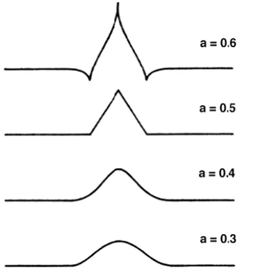
. Here the parameter a of the generating kernel is chosen to be 0.4 such that the resulting Gaussian kernel resembles the Gaussian probability density function with zero mean and unity variance. The shapes of Gaussian kernel for different values of a are shown in the Figure 1, for a = 0.6 the central positive mode is sharply peaked and is flanked by small negative lobes, for a = 0.5 the shape is triangular and for a = 0.3 it is flatter and broader. Thus fora
0
.
4
the one dimension Gaussian kernel isw
(
m
)
=[0.05 0.25 0.4 0.25 0.05]. This kernel can also be obtained by discretizing zero mean unity variance Gaussian probability density function.Figure 2: Shapes of Gaussian generating kernels for different values of a.
The Gaussian kernels being separable, the 2D Gaussian kernel is given by
0.0025
0.0125
0.0200
0.0125
0.0025
0.0125
0.0625
0.1000
0.0625
0.0125
0.0200
0.1000
0.1600
0.1000
0.0200
0.0125
0.0625
0.1000
0.0625
0.0125
0.0025
0.0125
0.0200
0.0125
0.0025
)
,
(
)
(
)
(
)
,
(
'n
m
w
m
w
m
w
n
m
w
(12)where
w
'(
m
)
is the transpose ofw
(
m
)
.IV.INPAINTING USING MULTIRESOLUTION GAUSSIAN PYRAMID
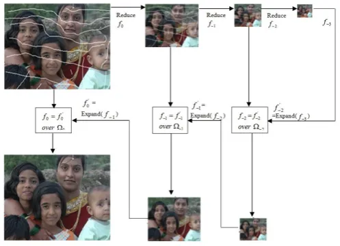
Generate all the possible routes. In this technique, a Gaussian pyramid [17] of resolutions
2
1 to2
L, of an input image is generated. The input imagef
0 is downsampled using Gaussian pyramid up to L resolution levelsto obtain images
f
1,f
2, …………,f
L at resolution levels2
1 to2
L, respectively. The damaged region0
progressively reduces to
l
02
l,
L
l
1
. After2
Lresolution levels the expand operation isThe damaged region,
L1 of imagef
L1 is considered and the pixels of this region are substituted by the pixels of corresponding region fromf
'L1. This substitution of Gaussian interpolated pixels assumes the processes of diffusion at that resolution. The expand operation followed by substitution is repeated for subsequent resolution levels up to original resolution to obtain inpainted image as shown in the inpainting algorithm. Figure 3 shows the inpainting procedure discussed for a typical image. The Gaussian pyramid for L=3 is constructed. The left top image is the image to be inpainted and the left bottom image is the resulting inpainted image.The Inpainting Algorithm
)
,
(
0
u
v
f
: Input image with
0 as damaged region to be filled-in and at the end of algorithm input image is replaced by inpainted image.L: Maximum number of resolution levels.
)
,
(
u
v
f
l : Image at resolution2
l of Gaussian pyramid with
l as inpainting region to be filled at 2l resolution.)
,
(
m
n
w
: Two dimension Gaussian kernel.Reduce operation: for
(
l
1
:
1
:
L
)
22 2
2
1
2
,
2
(
,
)
)
,
(
m n l
l
u
v
f
u
m
v
n
w
m
n
f
Store
[
f
l(
u
,
v
),
l]
end
)
,
(
u
v
f
L is the output image of the reduce operation with reduced damaged region
L , whereL
M
u
/
2
1
andL
N
v
/
2
1
.Expand and Substitution operation: for
(
l
L
:
1
:
1
)
22 2
2 '
1
(
,
)
2
,
2
)
,
(
m n l
l
w
m
n
n
v
m
u
f
v
u
f
f
l1(
u
,
v
)
f
l'1(
u
,
v
)
for
(
u
,
v
)
l1 EndV. IMAGE SET AND PERFORMANCE MEASURE
A wide variety of images is used to investigate the performance of proposed inpainting technique. The prior knowledge of the source, type or direction of lighting or camera parameters is not important in the present context. The techniques are independent of lighting and camera parameters and are not considered. Hence, images are collected from different sources viz. standard damaged images used by an image processing researchers (available on internet), synthetic images, biomedical image, amateur photographs taken by the author etc.
To test performance of the proposed technique, clean undamaged images are artificially degraded, and then inpainted. Although, the evaluation of inpainting technique/s is to be assessed by visual appearance and quality which is subjective in nature, a quantitative assessment would be more objective. There is no established quantitative measure for this evaluation. Hence in our work, the quantitative evaluation is performed by peak signal to noise ratio (PSNR). The PSNR is defined as-
inp clean
f
f
RMSE
PSNR
,
255
log
20
10 where
MN
v
u
f
v
u
f
f
f
RMSE
ijinp clean
inp clean
,2
)
,
(
)
,
(
,
(14)where
f
clean(
u
,
v
)
is clean undamaged image,f
inp(
u
,
v
)
is inpainted image and M × N is size of)
,
(
u
v
f
clean andf
inp(
u
,
v
)
. Please note that this measure is applicable only when the undamaged originalimage is available.
VI.RESULTS
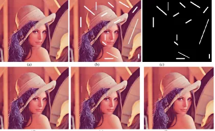
For every image to be inpainted, a binary mask image corresponding to inpainting area is created manually as shown in Figures (4c-7c). The white lines in the mask image correspond to damaged region and are the region of an interest (not shown). To establish the efficacy of our techniques, we artificially degrade the clean undamaged images by drawing random lines (artificial scratches), or pasting new objects on the images to create damaged image (artificial stains). These damaged images are inpainted (restored) and compared with the clean undamaged original images to calculate PSNR. Figures (4a-7a) show clean undamaged images. The scratches are created randomly to degrade the images as shown in Figures (4b-7b). These scratches are inpainted using Gaussian pyramid inpainting technique as shown in Figures (4f to 7f). The comparison of proposed technique is carried out by using the codes written by Bertalmio’s [2] (Figures (4d-7d)) in C++ and Stefan Roth [6] (Figures (4e-7e)) in MATLAB without any major changes. However their PSNR values and execution time is tabulated in Table 1 in comparison with proposed technique.
(a) (b) (c)
(d) (e) (f)
(a) (b) (c)
(d) (e) (f)
Figure 5 Inpainting of artificial lines and scratches on Cameraman’s image. (a): Clean image. (b): Damaged image. (c): Mask image. (d): Bertalmio’s technique, PSNR= 41.217 dB and Exe. time=135.386 S. (e): FoE technique with PSNR= 38.505 dB & Exe. time= 1119.111 S. (f): Gaussian pyramid technique, PSNR= 43.285 dB & Exe. time= 4.450 S.
(a) (b) (c)
(d) (e) (f)
(a) (b) (c)
(d) (e) (f)
Figure 7 Inpainting of artificial scratches on group photograph. (a): Clean photograph. (b): Damaged photo.. (c): Mask image. (d): Bertalmio’s technique, PSNR= 39.103 dB and Exe. time=5.032 S. (e): FoE technique, PSNR= 40.181 dB and Exe. time= 309.030 S. (f): Gaussian pyramid technique with PSNR= 40.103 dB and Exe. time= 3.754 S.
The PSNR values and inpainting time taken by each technique for each image is tabulated in Table 1. We observe that PSNR measure is in tandem with the visual quality i.e. better the PSNR and better is the inpainted image. The comparison of Gaussian pyramid technique is carried out with the techniques of Bertalmio’s and Stefan Roth (FoE). The proposed method shows the better performance in terms of PSNR, visual quality and execution time. By the observation of Table 1, we can say that Inpainting using multiresolution Gaussian pyramid is a fast technique and takes appreciably less time than that of Bertalmio’s and FoE techniques.
VII. CONCLUSION AND FUTURE WORK
The proposed algorithm is fast and produces good inpainting results. The results are better in terms of both quantitative assessment and visual quality than some of the previous methods [2, 6] proposed. For very large the result is not encouraging, as expected & the proposed technique only work for structure.
REFERENCES
[1] S. Masnou and J.M. Morel. Level-lines based disocclusion.5th IEEE International Conference on Image Processing, Chicago,IL,1998, pp 259-263.
[2] M. Bertalmio, G. Sapiro, V. Caselles, and C. Ballester. Image inpainting. Proceedings of SIGGRAPH. Computer Graphics Processing, 2000, pp 417-424.
[3] M. Olivera, B. Bowen, R. Mckenna and Yu-Sung Chang. Fast Digital Image Inpainting. Proceedings of the International Conference on Visualization, Imaging and Image Processing-VIIP 2001, pp.261-266, [PUB].
[4] M.M.Hadhoud, Kamel Moustafa and Shenoda. DigitalImage Inpainting using ModifiedConvolution Based Method. International Journal of Signal Processing, Image Processing andPpattern Recongnition, 2005, vol.1, No.1, pp 01-10.
Figure
No Image Name
PSNR (dB) Execution Time
(Sec) Bertalmio’s
Inpainting
FoE Inpainting
Proposed Inpainting
Bertalmio’s Inpainting
FoE Inpainting
Proposed Inpainting
6 Lena 49.765 45.664 50.688 128.580 445.947 2.625
7 Cameraman 41.217 38.505 43.285 135.386 1119.111 4.450
8 Fruits 38.489 34.514 42.2 506.567 2591.503 2.291
9 Group photo 39.103 40.181 40.103 5.032 309.030 3.754
[5] H.Noori, S.Saryazdi and H Nezamabadi-pour. A Convolution based Image Inpainting.1st Int conf on commn and Engg, University of Sistan & Baluchestan, Dec 2010, pp 130-134.
[6] A. Stefan Roth and Michael J Black. Field of Expert: A framework for Learning Image Priors. In IEEE Conference on Computer Vision and Pattern Recognition(CVPR), 2005, vol .2, .pp 860-867.
[7] H.Noori, S.Saryazdi and H. Nezamabadi-pour. ABilateral Image Inpainting. Transactions of Electrical Engineering, vol. 35, No. E2, printed in the Islamic Republic of Iran, Shiraz University, 2011, pp 95-108.
[8] A. Hirani and T. Totsuka. Combining Frequency and Spatial Domain Information for Fast Interactive Image Noise Removal.Computer Graphics, pp. 269-276, SIGGRAPH 96, 1996.
[9] M.Ashikhmin. Synthesizing natural images. Proc, ACM ,pp 217-226,2001.
[10] E. Simoncelli and J. Portilla. Texture characterization viajoint statistics of wavelet coefficient magnitudes. 5th IEEE Int’lConf. on Image Processing, Chicago, IL. Oct 4-7, 1998.
[11] A.Efros and T. Leung. Texture synthesis by non-parametric sampling. Proc. IEEE international Conference Computer Vision,pp. 1033-1038, Corfu, Greece, September 1999.
[12] A. Criminisi, & P.Perez Object Removal by Exempler-Based Inpainting. IEEE Trans, Image Proc, vol 13,no 9,pp 1200-1212,sept 2004.
[13] Yu-Sung chang. Fast Digital Image Inpainting,. VIIP 2001, pp. 261-266, [PUB],2001
[14] M. Bertalmio. L.Vese, G. Sapiro and S.Osher. Simultaneous Strucure and texture image Inpainting. UCLA CAM report 02-47,2003.
[15] H. Grssauer. A Combined PDE and Texture Sythesis Approach to Inpainting. Vol 3022, pp 214-224, 2004.
[16] Rajkumar L. Biradar and Vinaydatt V. Kohir. Texture Inpainting Using Covariance in Wavelet Domain. Journal of Intelligent Systems 2013; 22(3): pp 299–315
[17] Burt and Adelson. The Laplacian Pyramid as a Compact Image Code. IEEE Transaction on communication, vol.COM, No 4, April 1983, pp.532-540.
[18] J. Koenderink. The Structure of Images. Biological Cybernetics, New York, Springer-Verlag, 1984, pp363-370.
[19] S. Mallat. Multiresolution Approximation and Wavelet Orthonormal bases of L2( R). Transaction of the American Mathematics
Society, Sep 1989, pp 69-87.
[20] I. Daubechies. Orthonormal Bases of Compactly Supported Wavelets. Comm. Pure and Appl. Math., vol.41, 1988, pp. 909-996. [21] S. Mallat. A Theory for Multiresolution Signal Decomposition: The Wavelet Representation. IEEE Transaction. Pattern Analysis
and Machine Intelligence, vol.11, July 1989, pp 674-693.
[22] S. Mallat. A Wavelet Tour of Signal Processing. Second Edition, Academic Press, an Imprint of Elsevier. 1999.
[23] R. C. Crochiere and L. R. Rabinar. Interpolation and Decimation of Digital Signals. Proceedings of IEEE, vol.69, No.3, Mar 1981, pp 300-331.