Effect of magnetic island geometry on ECRH/ECCD and
consequences to the NTM stabilization dynamics
I. Chatziantonaki1,a, C. Tsironis2, H. Isliker1, and L. Vlahos1
1 Department of Physics, Aristotle University of Thessaloniki, 54006 Thessaloniki, Greece
2 School of Electrical and Computer Engineering, National Technical University of Athens, 15780 Athens, Greece
Abstract. In the majority of codes that model ECCD-based NTM stabilization, the analysis of the EC propagation and absorption is performed in terms of the axisymmetric magnetic field, ignoring effects due to the island topology. In this paper, we analyze the wave propagation, absorption and current drive in the presence of NTMs, as well as the ECCD-driven island growth, focusing on the effect of the island geometry on the wave de-position. A primary evaluation of the consequences of these effects on the NTM evolution is also made in terms of the modified Rutherford equation.
1 Introduction
NTMs limit tokamak performance leading to loss of confinement or even disruption [1]. Various tech-niques are under development for the control of these modes, with most important the application of localized ECCD. In the majority of models for the simulation of ECCD-based NTM stabilization, the analysis is performed on the basis of the unperturbed magnetic topology, taking into account only the flux surface of interest and ignoring any effects from the islands. However, the island topology introduces significant changes in the magnetic field and the plasma profiles as compared to the ax-isymmetric case, which may play a crucial role in the wave deposition and current drive.
In this work, we study the EC propagation, absorption and current drive in the presence of NTMs, using a ray-tracing code and a magnetic configuration that includes islands, and the resulting NTM dynamics are computed with the modified Rutherford equation. We focus on the effect of the island topology on the ECCD efficiency via the magnetic field, the flattening of the radial plasma profiles within the island region and the volumes of the flux surfaces onto which the wave is deposited. In Sec. 2 we introduce the non-axisymmetric magnetic configuration, in Sec. 3 we describe the ray-tracing scheme, which includes the computation of the volumes in the island topology, whereas in Sec. 4 the main results are presented and the implications of these results for the NTM dynamics are discussed.
2 Analytic description of the perturbed equilibrium
In order to derive an analytic model for the tokamak magnetic equilibrium including islands, we utilize the Clebsch form for the magnetic field,B=∇ψt× ∇θ+∇ϕ× ∇ψp, which is expressed in the toroidal coordinate system (r, θ, ϕ), withrthe minor radius (Rthe major radius),θthe poloidal angle,ϕthe toroidal angle, andψp,ψtthe poloidal and toroidal fluxes. For a more explicit expression, we consider ψt,ψpas functions ofr, θ, ϕand transform to orthonormal toroidal coordinates
B=∂rψt1
reˆr+∂rψp 1
Reθˆ−(∂θψp+∂φψt) 1
rReϕˆ, (1) a e-mail:[email protected]
DOI: 10.1051/ C
Owned by the authors, published by EDP Sciences, 2012 epjconf 201232/ 010
This is an Open Access article distributed under the terms of the Creative Commons Attribution License 2.0, which permits unrestricted use, distribution, and reproduction in any medium, provided the original work is properly cited.
Regarding the axisymmetric part of the magnetic field, a very convenient and widely-used repre-sentation is what is known as the ”vacuum magnetic field” [2]
Bt(r, θ)=
B0
1+ϵA(r) cosθ,Bp(r, θ)= ϵA(r)
q(r)Bt(r), (2)
whereBt,Bp are the toroidal and poloidal components, B0 the toroidal field on the magnetic axis, ϵA(r)=r/R0 the inverse aspect ratio andq(r)=dϕ/dθthe safety factor. Regarding the perturbation, since magnetic islands appear at flux surfaces whereq assumes rational values q(rs) = m/n, with rs the minor radius of the O-point andm,nthe toroidal and poloidal windings after which the field lines close, there should be two components of the magnetic field, a helicalBh and a radialBr. For a perturbation amplitudeεmn, in a first approach, these fields atr=rsare
Bh=Bp(rs) [
1− n mq(r)
]
,Br=εmn(r) sin(mθ−nϕ), (3)
For an implementation of the NTM topology we have to specifyεmn(r), and in order to preserve the divergence-free of the magnetic field we formulate the topology as a perturbationψp1to the back-ground poloidal flux, i.e.ψp=ψp0+ψp1. For the perturbation term we set the following form
ψp1(ψt, θ, ϕ)= ∑
m,n
(−1)mεmnexp(−r−a 2 c 2a2
w
)×cos (mθ−nϕ), (4)
From Eqs. (1) and (4), the radial magnetic field is
Br=(−1)mϵ m rRexp
[
−(r−rs)2 2w2
]
sin(ξ), (5)
whereξ = mθ−nϕand the exponential form of the radial dependence was chosen with the aim to make the perturbation local in radial direction.
The magnetic linesbρ(s)=(ρr(s), ρθ(s), ρϕ(s))=(x(s), y(s),z(s)) are defined by dbρ
ds =
B(bρ(s))
|B(bρ(s))|, (6)
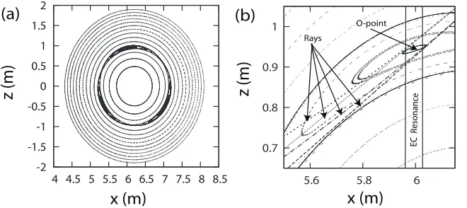
and we setds = √dr2+r2dθ2+(R0+r cosθ)2dϕ2, so that|dρ/ds| = 1 and the parameter sis the arc-length along the field line. The three differential equations (6) are solved numerically in Cartesian coordinates by using a 4th-order Runge-Kutta, adaptive step-size method. Figure 1 shows the poloidal cross section of the perturbed magnetic topology for the mode (m,n) = (3,2). The cross-section is calculated by determining the surface of section in the poloidal plane atϕ=0. The plasma parameters are chosen as relevant to ITER, major axisR0 = 6.2 m, minor axisα =1.9 m, toroidal field on the magnetic axisB0=5.51 T, and a monotonously increasing safety factor is assumed [2]
q(χ)= 4
(2−χ)(2−2χ+χ2), (7)
withχ=r2/α2, so thatq(0)=1 at the magnetic axis andq(α)=4 at the edge. The applied perturbation strength isϵ32 =0.005, corresponding to an island width of approximately 16cm.
In order to calculate the volumes into which the wave energy is deposited, it is important to have an analytical labeling of the flux surfaces in the island region. For an adequate description of the island’s morphology we derive a novel flux-surface labelΩthat starts from a more detailed description of the helical and the radial field than just using their values atr=rs, and also contains less approximations. For this reason, when computing the helical and radial field perturbation terms introduced above, we do not assume thatr=rseverywhere. The expression forΩis then given by
Ω =exp [
(r−rs)2 2w2
]
−1− 2m sin(β)×ln
[ Bθ0
n mq
′(r
s)+(−1)mϵ 1 R
1 w2cos(ξ)
]
z (m)
x (m)
(a)
(b)
-2 -1.5 -1 -0.5 0 0.5 1 1.5 2
4 4.5 5 5.5 6 6.5 7 7.5 8 8.5
0.7 0.8 0.9 1
5.6 5.8 6
EC
R
esonanc
e
Rays
O-point
z (m)
x (m)
Fig. 1.Poloidal cross section in Cartesian coordinates (a) for the entire poloidal plane and (b) zoomed into the magnetic island area, for the (3,2) mode and with ITER-like parameters.
Ωcan be normalized with a linear transformation in order to assume values in [−1,1] within the separatrix. The widthwof the magnetic island now being given by
w2 ≈ 8m
Bθ0mnq′(rs)R
(9)
Apart from the changes in magnetic topology, an NTM causes the plasma pressure to assume a constant value inside the the island chain. This effect in the pressure profile leads in turn to a flattening in the electron density and temperature profiles. In order to model this situation, we assume the den-sity and temperature profiles to be parabolic functions outside the island, as in the unperturbed case, constant in the island region and equal to the values at the outer island boundary.
3 Ray tracing, wave absorption and current drive
The Hamiltonian equations for the ray propagation in the GO approach are [3]
dk
dτ =− ∂H
∂r,
dr
dτ = ∂H
∂k, (10)
whereris the position of the ray,kis the wave vector,τis a parameter denoting the length along the ray path, and the Hamiltonian functionHis given by the dispersion relation of the wave,
H ≡det [(ω
c )2(
−k2I+kk)+ϵh
]
, (11)
whereϵh is the Hermitian part of the dielectric tensor andIthe unit tensor. Assuming cold plasma
propagation, one can adopt cold plasma response and get the expression for the Hamiltonian in [4]. The calculation of the wave absorption along the ray path can be done in terms of the imaginary part of the wave vector, as determined from the mode-specific dispersion relation [5]
dPw
dτ =−2 Im(k)·vgPw, (12)
wherevgis the group velocity. Knowing the power of the ray along its path, the powerdPwdeposited
in a small radial interval can be calculated from Eq. (12), and division by the corresponding volume dVs, which is contained between the two flux surfaces enclosing the radial interval, yields the absorbed wave power density. The total driven current per wave power defines the current drive efficiencyηCD
ηCD =2πR0ICD
Following that, the computation of the ECCD can be done in terms of the linear adjoint method [6]. For the accurate estimation of the wave power density, the calculation of the plasma volume be-tween two nearby flux surfaces is necessary, especially in case the local topology is expected to affect power deposition. We first need to calculate the total volumeVscontained inside one flux surface
Vs=− 1 n
∫ 2πn
0 ∫ ξ2
ξ1 ∫ r2
r1
(R0+rcosθ)rdr dξdθ, (14)
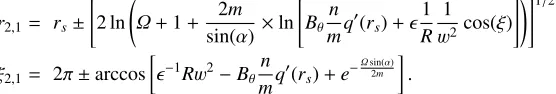
whereξ=mθ−nϕis the angle coordinate perpendicular to the helical line through the O-point and r1,r2,ξ1andξ2are the integration limits forrandξ, which are determined as follows: A given flux-surface has a unique value ofΩ=Ωi. The equationΩ(rs, ξ)=Ωidetermines the limitsξ1,ξ2in the helical (ξ) direction and at the radiusr=rs, and, forξin its integration interval [ξ1, ξ2], the equation Ω(r, ξ)=Ωidetermines the limitsr1(ξ),r2(ξ) in the radial direction as a function ofξ. This yields
r2,1= rs± [
2 ln (
Ω+1+ 2m sin(α)×ln
[ Bθn
mq ′(r
s)+ϵ 1 R
1 w2 cos(ξ)
])]1/2 ,
ξ2,1= 2π±arccos [
ϵ−1Rw2−B
θmnq′(rs)+e−
Ωsin(α)
2m ]
.
The absorbed power per unit volume can then be evaluated asdPw/dVs=(dPw/dτ)/(dVs/dτ).
4 Numerical Results
In this section, we present the numerical results on the effect of the magnetic island geometry on the EC wave propagation, power deposition and current drive. The wave is injected from the outermost flux surface (r = α), with the toroidal and poloidal launching angles such that the ray is targeted to a region very close to the O-point, and the EC resonance is located around the center of the island. We present results for the plasma and wave parameters of ITER:R0 =6.2 m,α=1.9 m,B0=5.51 T, ne0=1020m−3,neα=1019m−3,Te(0)=10 KeV,Te(α)=1 KeV,ω/2π=160 GHz (the fundamental O-mode),Pw0 =10 MW. Regarding the parameters of the NTM generating the magnetic islands, we throughout consider the mode (3,2), with a magnetic perturbation strength ε32 = 5·10−3, which corresponds to an island width of approximately 16cm.
In Fig. 1(b), we show ray paths in the presence of the NTM for two different poloidal launching angles. The figure also shows the corresponding ray paths in the absence of the NTM, i.e. in the unperturbed equilibrium, for a comparison of the two cases. The waves are injected at the poloidal angleθl = 30o, with the toroidal launching angle beingϕl =0o. For the assumed profiles ofB,n
e, Te, and the value ofω, the region of the EC resonance is located aroundR=6 m and marked by two vertical lines. The ray propagation is seen not to be much affected by the magnetic field of the island, since the relative magnetic perturbation strength (∼10−3) is small.
As explained above, with a magnetic island present, the wave power is absorbed in smaller flux-surface volumes, with the direct consequence that the ECCD is strongly increased. This is shown in Fig. 2 for a typical case, where the wave is injected at the poloidal angleθl =30o and the toroidal launching angle is 0o. In the presence of an NTM, the absorbed power density is found to be nearly 2 times larger than the one in the unperturbed case. The driven current density has a similar behavior, attaining a value almost 2.5 times larger than in the absence of the NTM perturbation.
Based on the previous results, the question arises whether the effects of the island geometry on the ECCD efficiency also play a significant role in NTM stabilization. Here, only a preliminary in-vestigation of this issue is made. The NTM dynamics can sufficiently be described by the modified Rutherford equation, which is the established model for the dynamic evolution of NTMs
τr rs
dW dt =rs
( ∆′+∆′
BS+∆′CD )
, (15)
whereWis the half-width of the magnetic island,τr=936.4r2
sis the resistive time-scale of the plasma, ∆′=−mis the classical TM stability index,∆′
R (m)
J
cd
(MA\m )
R (m)
2
dP/dV (MW/m
3 )
(a)
(b)
0 2 4 6 8 10 12
5.4 5.6 5.8 6 6.2
perturbed unperturbed
0 0.1 0.2 0.3 0.4 0.5 0.6 0.7 0.8
5.5 5.7 5.9 6.1 perturbed
unperturbed
Fig. 2.Deposited wave power per unit volumedPw/dVs(a) and the corresponding driven current density (b) as a function ofR, for the cases of propagation with a (3,2) NTM mode present and without perturbation.
0 0.05 0.1 0.15 0.2
−60 −50 −40 −30 −20 −10 0
w/α
τ
r
/r
s
dw/dt
ECCD+island no ECCD
ECCD
ITER m/n = 3/2
φl = 0°
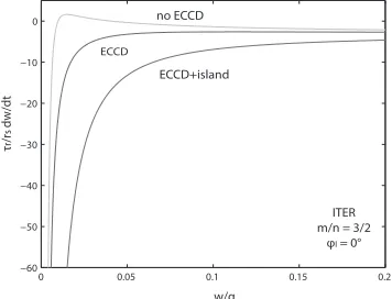
Fig. 3.Phase diagram of the modified Rutherford equation form/n=3/2 andϕl=0o.
current, which becomes significant for high values of the plasma pressure, and∆′CDis the term which represents the stabilizing effect of the ECCD on the island. The∆′-indices are defined as
∆′ BS =
√ϵAβP
W Lq Lp W
2
W2+W2 d
+ W2
W2+28W2 b
−W
2 pol
W2
, ∆CD′ =−0.31Lqµ 0jCD0 2Bp
[ 34dCD
W2 gwd+ 4√π
dCD
(1−gwd) ]
.
In the above,ϵAis the aspect ratio of the tokamak,βP =2µ0P/B2 is the ratio of the plasma pressure over the magnetic pressure,LqandLpare the shear lengths of the safety factor and the plasma pressure, dCD is the wave power deposition width (jCD0 andgwd are defined below) and Wd ,Wb, Wpol are characteristic threshold values for the island width [7].
Apart from the total driven current, two more characteristics of the ECCD are important for NTM stabilization, the spatial distribution of the driven current density and its efficiency in replacing the missing bootstrap current. The current density is assumed here to exhibit a Gaussian distribution in space,jCD= jCD0exp
[
−(r−rs−rmis)2/dCD2 ]
, wherermisis the small distance of misalignment of the ECCD deposition center from the island’s O-point. The efficiency of the ECCD in stabilizing the NTM is described by the parametergwd=0.3dW
CDU(2−W/dCD)+exp (
−dCD W
)
U(W/dCD−2) [7].
For the plasma and wave parameters we use the same ITER-relevant values as in the previous section, and for the parameters newly introduced in this section we setβP = 0.5,Lq/Lp = 1,wd = 0.01rs, wb =0.02rs,wpol =0.015rs,rmis=1 cm. Fig. 3(a) shows that (i) without ECCD applied the island is unstable to grow in a wide range of widths, (ii) with ECCD applied but calculated without taking the island topology into account, there is still a region of unstable widths, much smaller now in extent, and (iii) with ECCD applied and calculated by taking the island geometry into account, there is an effective NTM stabilization, sincedW/dthas becomes negative for all widths. The reason for the effectiveness is the peaking of the ECCD profile when the island topology is taken into account.
5 Summary and Discussion
In this paper we studied EC wave propagation, absorption and current drive in the presence of magnetic islands, using ray tracing and a novel approach to the modeling of a tokamak magnetic field that includes islands, and investigated the effects of the island geometry on the NTM dynamic evolution. Up to now, this issue has been analyzed by ignoring any effects from the island topology on the ECCD efficiency. The analytic model for the magnetic islands superimposed onto the tokamak equilibrium field is more realistic than the standard models adopted so far in the literature, using a novel surface labeling in the island region which improves the precision in the determination of the flux-surface volumes and leads to increased accuracy in the calculation of the power deposition.
Our main results imply that: (a) In most cases, the propagation until the O-point is little affected by the magnetic island topology, due to the very small magnitude of the perturbation, with any effects owed to the flattening of the plasma pressure within the island region. (b) The absorbed wave power and the driven current are affected significantly by the island geometry, namely enhanced, the energy is absorbed and redistributed by the plasma particles in flux-surface volumes much smaller than the ones in an axi-symmetric topology. (c) The use of an island topology allows a more accurate estimate of the NTM stabilization effect of ECCD, and it turns out that the increased ECCD peaking in the islands topology results in a much better efficiency of NTM stabilization, i.e. stabilization can be achieved with less wave power than the one estimated in axisymmetric geometry.
Concerning the basic assumptions made in our modeling approach, the routines for the compu-tation of the wave propagation, absorption and current drive are based on linear methods that do not account for (a) wave diffraction, (b) trapping of particles in the island chain, or (c) nonlinear effects due to the very large values that the absorbed power density may attain. Also, the effect of the island geometry on the NTM dynamics has been studied in terms of a quasi-self-consistent coupling of the wave propagation solver to the equation governing the island dynamics. The development of a fully self-consistent model, either in terms of changing the magnetic topology at certain time slices during the wave propagation, or with ray tracing in time-dependent fields, is under way. Other studies have been made [8], simulating the ECCD process in more detail than with the linear models used here, yet without accounting for the consequences of the island topology on ECCD, which find that the transport properties enhance the current drive efficiency compared to the axisymmetric case.
References
1. R. J. LaHaye, R. Prater, R. J. Buttery, N. Hayashi, A. Isayama, M. Maraschek, L. Urso, and H. Zohm.Nucl. Fusion, 46:451, 2006.
2. R. Balescu. Transport processes in plasmas. 2. Neoclassical transport theory. North-Holland, 1988. 3. L. Friedland and I. B. Bernstein.Phys. Rev. A, 22:1680, 1980.
4. E. Poli, A. G. Peeters, and G. V. Pereverzev.Comput. Phys. Commun., 136:90, 2001. 5. E. Westerhof. Implementation of TORAY at JET. FOM Rijnhuisen, 1989.
6. R. H. Cohen.Phys. Fluids, 30:2442, 1987.
7. L. Urso. Modelling and experiments on NTM stabilisation at ASDEX upgrade. Ludwig-Maximilians Universitaet Muenchen, 2009.