Numerical comparison between different strength after impact
test procedures
M. Klaus,aand H.-G. Reimerdes,b
RWTH Aachen University, Department of Aerospace and Lightweight Structures, Wuellnerstr. 7, D-52062 Aachen, Germany
Abstract. Different procedures are established to investigate the residual properties of sandwich panels after impact damage. Two used procedures for the testing of this prop-erties are compression after impact (CAI) and 4-point bending. In this paper a numerical procedure is presented for a first prediction of the behaviour of pre-damaged sandwich specimens under different boundary conditions (or testing procedures).
A sequence of impact experiments using a drop tower is performed to assess the damage tolerance of sandwich panels with aramid paper foldcores and CFRP skins. The tested im-pact energy range allowed to investigate a variety of damage scenarios from barely visible damages (BVID) to fibre fractures in all plies of the impacted face sheet. Additionally 4-point bending tests are performed with the panels previously damaged by impact load-ings to assess the residual bending strength of these samples. The developed numerical procedure is used to reproduce these experiments (the impact as well as the 4-point bend-ing tests). Also the same procedure is employed in an attempt to predict the behaviour of samples with the same build-up in simulated compression after impact tests.
1 Introduction
Due to their high bending stiffness combined with low mass sandwich panels are promising compo-nents for lightweight structures. Also the possibility to optimise the sandwich structures by using com-binations of different materials and configurations makes them applicable in a broad range of fields. On the other hand sandwich structures (especially with composite components) are sensitive to a variety of damage scenarios. One of these scenarios is impact damage [1]. Especially in aerospace applications impact damage tolerance is a critical design parameter. Experimental investigations revealed signif-icant reduction of compression and bending strength even in case of barely visible damage (BDIV) [2]-[6].
In this paper a procedure to simulate low velocity impact tests as well as the residual strength tests of pre-impacted sandwich structures is presented. The impact simulations are performed using an explicit code. Afterwards the resulting deformations and damages in the face sheets and the core are transferred from the explicit impact simulation to a new model. Using this new model implicit non-linear static residual strength simulations are performed.
The explicit finite element simulations are compared to experiments performed with a drop tower. Furthermore the residual strength simulations are compared to experimental 4-point bending tests with impacted and undamaged sandwich panels.
The developed numerical procedure is used to investigate the behaviour of the pre-impacted sand-wich panels in 4-point bending and compression after impact. Both procedures are the most established approaches to asses the residual strength properties of flat sandwich panels after one of the face sheets
a e-mail:[email protected]
b e-mail:[email protected] © Owned by the authors, published by EDP Sciences, 2010
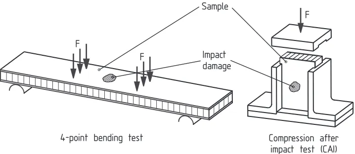
Fig. 1.Residual strength after impact procedures
was exposed to impact loadings. This kind of comparison should serve as a first prediction of the in-fluence of the boundary conditions, which are specific for the different test procedures, on the residual strength due to small impact damages.
All experiments and simulations in this paper are performed using sandwich panels with a foldcore and FRP skins.
2 Residual strength testing procedures
The different set-ups for the two investigated residual strength testing procedures are schematically shown in Fig. 1. The 4-point bending test is designed to obtain information about the bending stiffness and bending strength of a sandwich panel [7]. The test set-up is built to introduce a constant bending moment into the impacted area of the sandwich sample. To do this the sample is loaded at four posi-tions. The force is introduced by four steel cylinders. Rubber pads are placed between the cylinders and the samples to reduce lateral forces. The bending moment in the tested area can be easily computed from the distance between the inner load introductions (Li) and between the outer load introductions (Lo):
M= F(Lo−Li)
4 (1)
This bending moment introduces compression in the damaged upper skin and tension in the undam-aged lower skin (in case both face sheets are equally thick):
σ=±MH
2I =
FH(Lo−Li)
4bt(H−t)2 (2)
withHthe overall sandwich thickness,tthe skin thickness andbthe sample width.
In case of compression after impact tests both face sheets (damaged and undamaged) are com-pressed equally during the procedure. Additionally the sample is usually stabilized laterally to prevent global buckling of the panel. The initial compression stress in both skins is given as:
σ= F
2bt (3)
More information about the set-up of the CAI-procedure can be found in [1], [2] and [8].
3 Specimens
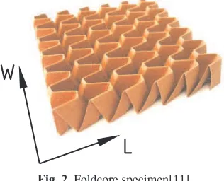
origami-like structure in a continuous process [9], [10]. Aramid fibre paper impregnated with phenolic resin is used as core material. The core has a height of 20 mm and an overall density of 137.5 kg/m3.
Fig. 2.Foldcore specimen[11] Fig. 3.Unit cell geometry
Both face sheets of the sandwich are CFRP laminates. The used composite structure has 16 plies in a quasi-isotropic layup ([45◦/90◦/-45◦/0◦/45◦/90◦/-45◦/0◦]s). The thickness of the face sheets is 2 mm. The cores as well as the sandwich samples are manufactured at the University of Stuttgart.
4 Numerical Procedure
4.1 Models Used for Dynamic Simulations
The impact simulations are performed with LS-Dyna using an explicit solver. 4-node Belytschko-Lin-Tsay shell elements (uniformly reduced integration) are used for the impactor, the face sheets and the core. Different material models for the different parts of the model are chosen to satisfy the behaviour the investigated materials. For the aramid paper cell walls an elasto-plastic material is adopted. The failure criterion for the paper is based on the maximum plastic strain. For the face sheets a composite material model is used. Unidirectional layers in the composite shell structures can be defined with this material model. Additionally according to the Chang-Chang criteria four different failure modes can be specified (fibre tensile/compression and matrix tensile/compression failures) [12]. As long as none of these criteria is fulfilled the material remains elastic. The material properties for the CFRP face sheets are derived from the tensile tests of the face sheet material or taken from the data sheets of the investigated laminates. The support is modelled as a rigid wall.
Due to incompatible meshes of the core and the face sheets, these parts of the model are connected to each other by tied contact interfaces. These contact algorithms are able to translate the translational as well as the rotational degrees of freedom between the face sheets and shell edges of the foldcore.
The impactor is assumed to be rigid. The density of the rigid impactor shells is adjusted to get an overall mass of the actual impactor of 1.56 kg. The impact energy is controlled by the initial vertical velocity of the impactor. The interaction between the impactor and the upper face sheet is accom-plished by a contact algorithm with the spherical impactor as the master surface and the upper face sheet as the slave surface. Additional contact algorithms prevent the forceless penetration of the core after a possible destruction of the face sheet and also the self-penetration of the walls inside the core.
4.2 Transfer of Deformations and Damages and the Models Used for Static Analysis
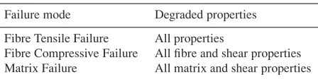
Table 1.Degradation of properties due to the failure modes
Failure mode Degraded properties
Fibre Tensile Failure All properties
Fibre Compressive Failure All fibre and shear properties Matrix Failure All matrix and shear properties
For all elements of the upper face sheet, where in one or more plies the condition for at least one of the failure modes is satisfied during the LS-Dyna computation, a new element for the Abaqus model is generated. These elements are provided with degraded properties in the affected ply (or plies). For the computations described in this paper the affected properties (Table 1) are reduced to a value of 10% of the original values. Apart from that the definition of the material properties in the Abaqus model is similar to the material properties used for the impact simulations. The paper walls of the core are elasto-plastic. The single plies of the face sheets are able to fail according to the Hashin failure criteria [13], [14]. As during the impact computations the meshes of the sandwich skins are tied to the core wall mesh by a contact algorithm. Additionally in case of the 4-point bending tests the filler material in the outer region of the samples is modelled with standard 8-node brick elements with elastic material behaviour . The distorted mesh which remains after the impact loads have subsided is used as the initial mesh for the static residual strength simulations.
5 Experimental Set-up and Test Procedure
5.1 Impact Tests
The impact tests are performed with a drop tower. The impactor has a mass of 1.56 kg and slides along a vertical rail. The impactor head which actually contacts the sample is ball-shaped and is made of steel. The diameter of the head is 1 inch (25.4 mm).
During the experiments the specimens (see Sect. 3) are completely supported by a laminated wood plate. The outer regions of the investigated plates are fixed by spring-loaded nylon plates to prevent spring-back.
To measure the reaction force two acceleration sensors are integrated into the impactor head. The analogue recording of the measuring data is accomplished with a sampling rate of 100 kHz. A laser measuring system mounted at the drop tower records the displacement of the impactor. The same system allows to measure the exact impact velocity and thus the exact impact energy.
5.2 4-point bending tests
4-point bending test are performed to asses the drop in bending strength due to impact damages. The set-up is shown in Fig. 1. The distance between the inner load introductions is Li = 120mm and between outer load introductionsLo = 350mm. The tested samples had a width ofb = 91mm and an overall length of 400mm. The sandwich core outside the inner load introductions is replaced by a much stiffer filler. This modification prevents shear-induced failure in the outer regions of the samples during the tests. Because of this the needed sample length can be reduced significantly. The test set-up is designed according to DIN EN 6061 [7]. All samples are tested beyond the ultimate load.
6 Experimental Results
0 2 4 6 8 10
0 0.5 1 1.5 2 2.5 3 3.5 4
Force [kN]
Time [ms] 5J (2x) 10J (2x) 20J (2x) 40J (2x)
Fig. 4.Contact forces (Impact, experimental)
damages after the impact range from nearly invisible (5 Joule) to a clear visible dent with first fibre fractures (20 Joule) to fibre fractures in all plies (40 Joule). However earlier investigations with similar configurations suggest for all tested impact energies a much higher invisible damage extent.
Comparisons between contact forces caused by the different impact energies are shown in Fig. 4. The maximum force levels increase with the impact energy between 5 and 20 Joule. For 40 Joule the force level decreases again. This phenomenon can be explained by the switch of the primary damage process from mostly delaminations and matrix damages to extensive fibre damages.
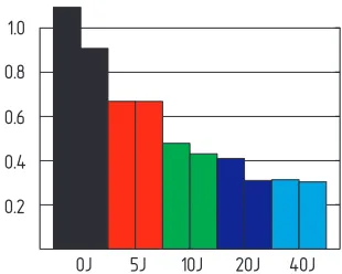
With all impacted and non-impacted samples bending tests are performed. In case of the impacted specimens the damaged face sheets are subjected to compression. In Fig. 5 the results are summarized. The initial non-linearity is caused by the compression of the rubber pads between the sample and the test set-up. The linear slope in the force-displacement diagrams (bending stiffness) is very similar for nearly all tests. The decrease in bending strength however is significant. The relative bending strength in comparison to the measured values for non-impacted panels is summarized in Fig. 6.
0 5000 10000 15000 20000 25000 30000 35000 40000 45000
0 2 4 6 8 10 12 14
Force [N]
Displacement [mm] 0J(2x)
5J(2x) 10J(2x) 20J(2x) 40J(2x)
Fig. 5. Force-displacement diagrams (4-point bending tests, experimental)
Fig. 6.Relative bending strength after impact (4-point bending tests, experimental)
7 Numerical Results
7.1 Impact simulations
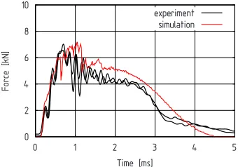
The impact simulations show a good agreement in the prediction of the maximum contact load for most of the impact energies (for example see Fig. 7). Also the duration of the impact event (contact between impactor and the skin with high force levels) agrees with experimental data. As during the experiments only barely visible indentations remain after the lowest energy impacts and parts of the face sheet are destroyed at the impact position (fibre failure in all plies) after a 40 Joule impact.
0 2 4 6 8 10
0 1 2 3 4 5
Force [kN]
Time [ms] experiment
simulation
Fig. 7.Contact forces(40 Joule impact, experimen-tal and simulated)
0 5000 10000 15000 20000 25000 30000 35000 40000 45000
0 2 4 6 8 10 12 14
Force [N]
Displacement [mm] undamaged
experiment simulation
Fig. 8. Force-displacement diagrams (4-point bending after a 40 Joule impact)
7.2 Residual strength simulations
7.2.1 4-point bending simulations
For the 4-point bending simulation also a good agreement between the simulations and experiments could be achieved regarding the linear force increase (bending stiffness). The exact collapse force is in all cases slightly overestimated (see for example Fig. 8). This seems reasonable due to the non-considering of inter-ply delaminations during the impact simulations. Also most of the possible im-perfections in the real samples could not be adopted to the used models. The initial non-linearity observed during the experiments is caused by the rubber pads. This effect is not considered during the simulations.
Similar to the experiments the ultimate collapse is caused by inward wrinkling of the damaged face sheet. The elements along the buckle fail causing a drop in bearable load. The buckle/crack originates at the impact position and runs along the width or slightly inclined to it. The core is crushed beneath the buckle. There is a strong dependency between the amount of damage and deformations caused by the impact and the bending strength of the damaged sample (see Fig. 9).
7.2.2 CAI simulations
0 5000 10000 15000 20000 25000 30000 35000
0 1 2 3 4 5 6 7 8
Force [N]
Displacement [mm] 0J
5J 10J 20J 40J
Fig. 9. Force-displacement diagrams (4-point bending, simulated)
0 50000 100000 150000 200000 250000
0 0.2 0.4 0.6 0.8 1 1.2 1.4
Force [N]
Displacement [mm] 0J
5J 10J 20J 40J
Fig. 10.Force-displacement diagrams (CAI, simu-lated)
undamaged sandwich skin to buckle outwards. After collapse of the pre-damaged skin the remaining load is supported almost completely by the second skin. There is also a significant drop in compression strength due to the impact damage, even for the lowest investigated energies (5 Joule). See Fig. 10) for a summary of the load-displacement diagrams.
7.2.3 Comparison between 4-point bending and CAI simulations
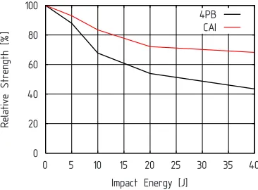
The most obvious difference to the 4-point bending tests is the need for much larger forces during the experiments for CAI. For example for the investigated sandwich type (see Sect. 3) and assuming the same sample width the needed force to cause the same compression stress in the damaged skin is more than 5 times larger in case of the CAI tests compared to the 4-point bending tests (compare Fig. 9 and Fig. 10 and also Eq.(2) and Eq.(3)). Also the behaviour of the samples seems to be more sensitive to changes in boundary conditions.
In direct comparison of the performed simulations the drop in strength is in case of 4-point bending tests about twice as high as in case of CAI (see Fig. 11). So the two testing procedures present two different residual strength after impact values. Further investigations are needed to understand the influence of the different boundary conditions, loading conditions and the different failure modes. Also numerical simulations and experimental investigations with large panels under realistic loadings are needed to assess which of the two testing procedures discussed here produce a more realistic assessment of damage tolerance for real world applications.
0 20 40 60 80 100
0 5 10 15 20 25 30 35 40
Relative Strength [%]
Impact Energy [J] 4PB
CAI
8 Conclusions
A numerical procedure is presented which allows the investigation of different residual strength sce-narios for sandwich panels damaged by low-velocity, low-energy impacts. The numerical result are compared to 4-point bending experimental ones and are in good agreement. This approach can be used to predict the behaviour of damaged or undamaged sandwich panels in a certain set of given boundary conditions. For example planned tests could be simulated in advance with a given sandwich type. And also the behaviour of promising core/skin combinations could be assessed preliminary, without actu-ally manufacture them or perform an expensive testing program. The question which residual strength test procedure is the most applicable to assess the impact tolerance of sandwich panels remains a subject of research.
9 Acknowledgements
This work was supported by the European Commission, Priority Aeronautics and Space, Project CEL-PACT (Cellular Structures for Impact Performance), Contract AST5-CT-2006-031038. The funding is gratefully acknowledged.
References
1. D. Zenkert,The Handbook of Sandwich Construction(EMAS publishing, 1997)
2. R. Harvey, M. Kemp, K. Wolf,A Compression Test Method for Damaged Fibre-Reinforced Plastic
Sandwich Specimens(Sandwich Construction 3, Vol II, pp.669-676, 1996)
3. A. Shipsha, D. Zenkert,Compression-After-Impact Strength of Sandwich Panels with Core Crush-ing, (Appl. Comp. Mats., 12, pp.149-164, 2005)
4. G.A.O.Davies, D.Hatchings, T.Besant, A.Clarke, C.Morgan,Compression After Impact Strength of
Composite Sandwich Panels, (Int. J. of Comp. Structures, 63, pp.1-9, 2004)
5. W. G¨ottner, M. Klaus, H.-G. Reimerdes,Bending strength of sandwich panels with different cores
after impact, (ECF16 - 16th European Conference of Fracture, 2006 )
6. M. Klaus, H.-G. Reimerdes, Residual Strength Simulations of Sandwich Panels After Impact (ICCM17 - 17th International Conference on Composite Materials, 2009 )
7. DIN EN 6061: Aerospace series, Fibre reinforced plastics, Test method,Determination of sandwich
flexural strength, 4-point bending(1995)
8. Boeing Specification Support Standart BSS 7260 Rev B,Advanced Composite Compression Tests (1986)
9. S. Fischer, S. Heimbs, S. Kilchert, M. Klaus, C. Cluzel,Sandwich Structures with Folded Core:
Manufacturing and Mechanical Behaviour, (SAMPE Europe, 2009)
10. R. Kehrle, K. Drechsler, Manufacturing of folded core structures for technical applications, (SAMPE Europe, 2004)
11. S. Heimbs, T. Mehrens, P. Middendorf, M. Maier, A. Schumacher,Numerical Determination of the
Nonlinear Effective Mechanical Properties of Folded Core Structures for Aircraft Sandwich Panels,
(6th European LS-DYNA Users Conference, 2007)
12. F.K. Chang, K.Y. Chang, A Progressive Damage Model for Laminated Composites Containing
Stress Concentrations, (J. of Composite Materials, 21, pp. 834-855, 1987).
13. Z. Hashin, A. Rotem,A Fatigue Failure Criterion for Fiber Reinforced Materials, (J. Comp. Mats. Vol. 7, pp.448-464, 1973)